

Page 1
69-0115-11
L4064B, L4064R
WARNING
CAUTION
Universal Combination Fan and
Limit Controllers
INSTALLATION INSTRUCTIONS
APPLICATION
INSTALLATION
These combination warm air fan and limit controllers
are suitable for various types of forced air heating
systems. The controllers have 2 switches; one which
opens the limit circuit if the plenum temperature
exceeds the preset safety limit; it resets automatically.
The other switch turns the fan on and off. The fan is
turned on and off according to plenum temperature.
The L4064R has a special high temperature range
suitable for gravity heating systems. All models may
be used as limit controllers by wiring only the limit
side. Limit contacts are suitable for both line voltage
and low voltage. For low voltage applications, the
brass jumper must be removed.
OPERATION
As the plenum temperature rises, the coiled bimetal
sensing element of the control warps and
mechanically makes the fan contacts (at the FAN ON
temperature setting). During normal operation, the
call for heat ends before the LIMIT setting is reached
and the fan contacts break as the plenum
temperature falls and the FAN OFF setting is reached.
If the call for heat continues until the temperature in
the plenum rises to the LIMIT setting, the bimetal
element will mechanically break the limit contacts
and de-energize the heating control circuit.
When Installing this Product...
1. Read these instructions carefully. Failure to fol-
low them could damage the product or cause a
hazardous condition.
2. Check the ratings given in the instructions and
on the product to make sure the product is suitable for your application.
3. Installer must be a trained, experienced service
technician.
4. For 230 VAC application, use of double insu-
lated cable is required.
5. After installation is complete, check out product
operation as provided in these instructions.
If limit switch is used on a low voltage
circuit, failure to remove brass jumper can
cause electrical shock hazard and/or
damage to low voltage controls.
1. Disconnect power supply before connecting
wiring to prevent electrical shock or equipment
damage.
2. When connecting cable or conduit to control,
avoid straining the control case.
Follow furnace or burner manufacturer’s instructions,
if available. Maximum element temperature is:
L4064B—350 ºF (177 ºC).
L4064R—250 ºF (121 ºC) above limit setting.
Maximum switch temperature is:
L4064B,R—190 ºF (88 ºC).
Page 2
L4064B, L4064R UNIVERSAL COMBINATION FAN AND LIMIT CONTROLLERS
M31164
FURNACE
PLENUM
REQUIRE 1-9/16 IN
[39.7mm] DIAMETER
HOLE IN PLENUM
32612A SWIVEL
BRACKET
Do not exceed the following electrical ratings
(amper es):
Table 1. Electrical Ranges
120 Vac 240 Vac
FAN LIMIT FAN LIMIT
Full Load 14 8 7 4
Locked
Rotor
Pilot Duty: 2 A at 24 Vac; 0.25 A at 0.25 to 12 Vdc.
Maximum Combined Connected Load: 2000 VA. 75 ºC
(167 ºF) (min.) field wiring required. Wiring must
conform to NEC Class 1 requirements.
Approval
—IP20 compliance
— Classified as TR/TW
— CSA certified file #095329
— UL listed file #MP3387
— DVGW certified ID-No:
CE-0085BM0320 for B type only
84 48 42 24
LOCATION
If this is a replacement installation, locate the L4064
in the same location as the control being replaced.
Sensing tube length should be same as old control. If
this is a new installation, the element should be
installed only by a trained, experienced service
technician according to the furnace manufacturer’s
instructions. The element must not touch any internal
part of the furnace.
NOTE: The electrical rating is at maximum switch
temperature of 190 ºF (88 ºC). If plenum surface temperature exceeds 190 ºF (88 ºC),
heat insulating material or mounting bracket
must be used.
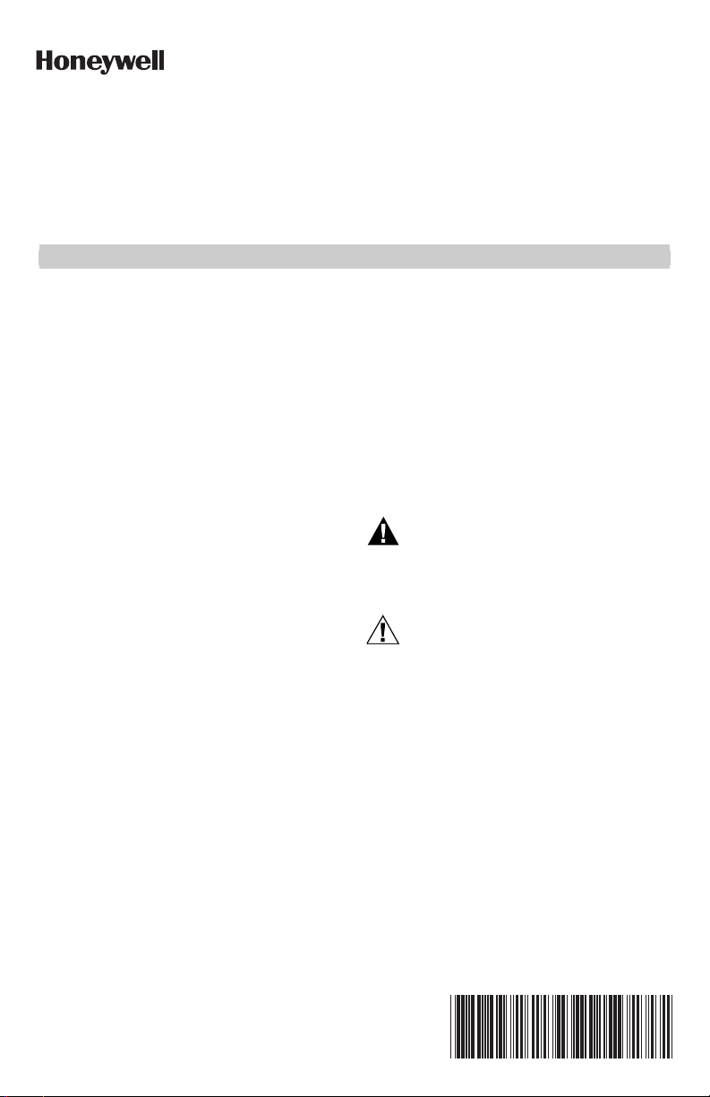
Surface Mounting (Fig. 1)
L4064B—Hole in plenum should be just large enough
to accommodate the 3/4 in.(19.1 mm) diameter
element tube. A 13/16 in. (20.6 mm) diameter hole is
recommended.
1. Remove cover by removing screw, squeezing
sides and pulling off. Insert element in plenum
and mark location of mounting holes. Make sure
the case is snug against the plenum before
marking the mounting holes.
2. Punch or drill holes for mounting screws.
3. Place insulation between plenum and case
if necessary.
4. Fasten controller securely with mounting
screws.
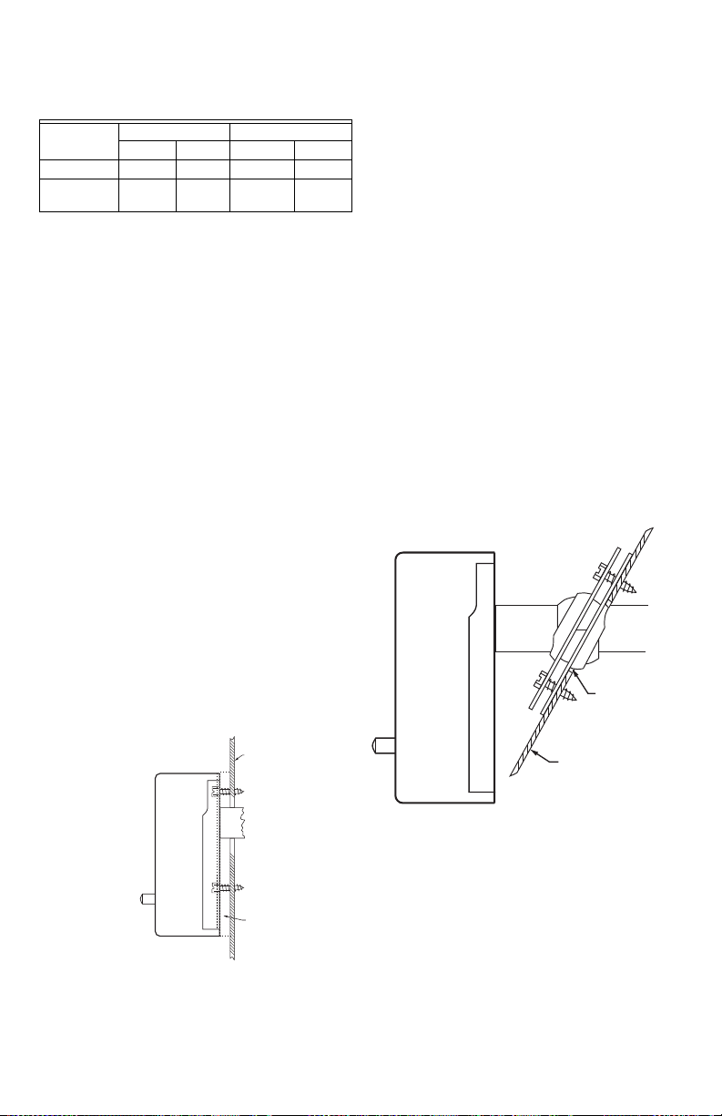
Swivel Mounting (Fig. 2)
The L4064B and L4064R may be swivel-mounted. The
swivel bracket requires a 1-9/16 in. (39.7 mm) hole in
the plenum.
1. Use bracket as a template to make the location
of mounting holes in plenum. Drill or punch
holes for mounting screws.
2. Fasten the bracket in place with furnished
screws. Start the screws but do not tighten.
3. Insert element tube through bracket, straighten
controller, and fasten. Tighten the mounting
screws securely. It may be necessary to rotate
the bracket to tighten all screws securely.
MOUNTING
The devices may be mounted as follows:
L4064B — Swivel mount
L4064R — Swivel mount
FURNACE
PLENUM
ADD HEAT
INSULATING
MATERIAL IF
NEEDED
M31163
Fig. 1. Surface mounting for L4064B requires a
69-0115—11 2
13/16 in. (20.6 mm) hole.
Fig. 2. Swivel mounting requires a 1-9/16 in.
(40 mm) diameter mounting hole for element
insertion.
Page 3

L4064B, L4064R UNIVERSAL COMBINATION FAN AND LIMIT CONTROLLERS
Fig. 3. Swivel mount (front view).
M34080
WIRING
Disconnect power supply before beginning
installation to prevent electrical shock or equipment
damage. All wiring must comply with local electrical
codes and ordinances or in the absence of local codes
with the National Electrical Code ANSI Cl-1981-NFPA
70. Follow burner or furnace manufacturer’s
instructions if available; otherwise, see Fig. 5 and
proceed as follows.
IMPORTANT
The brass jumper is the breakaway type. It
must be removed when the limit is used in the
low voltage circuit. To remove jumper, break
with a needlenose pliers and remove completely. Once removed, it is not replaceable.
See Fig. 5
for location.
1. If cable is used, we recommend using a strain-
relief bushing in the knockout. Bushing is provided with control.
2. Refer to the following section for type of wiring
connections (standard wire push-in terminals or
female receptacle).
AB
L4064
FAN
JUMPER
REMOVED
(HOT)
L1
POWER
1 1
SUPPLY
L2
LIMIT
SIDE
SIDE
FAN
MOTOR
1
ADD DISCONNECT MEANS AND OVERLOAD PROTECTION AS REQUIRED.
2
TO CONTROLLED LOW VOLTAGE EQUIPMENT.
3
TO CONTROLLED LINE VOLTAGE EQUIPMENT.
L4064
FAN
LIMIT
SIDE
FAN
MOTOR
JUMPER
IN PLACE
3
POWER
SUPPLY
SIDE
2
Fig. 4. Wiring Diagram for L4064.
Wiring Connections
When connecting cable or conduit to this controller,
use care to avoid strain on the control case.
Connections can be made to standard wire push-in
terminals or female receptacles for 1/4 in. (6.4 mm)
male flag connectors on both the fan and limit
switches (Fig. 5).
For Standard wire Push-in terminals
Connect wires to the terminals as follows:
1. Use Nos. 14,16, or 18 solid wire or Nos. 14 or 16
stranded wire, depending on electrical requirement.
2. Strip insulation from wires the distance shown
by the strip gauge on the controller. If wire insulation is 4/64 in. (2 mm) thick, strip additional
1/4 in. (6 mm) to ensure wire seats securely in
push-in connectors.
C
L4064
FAN
SIDE
FAN
MOTOR
1
(HOT)
L1
L2
(HOT)
L1
POWER
SUPPLY
L2
3. Solid wire may be inserted directly into the ter-
minal holes. If stranded wire is used, insert a
small screwdriver into the slot next to the terminal. Push screwdriver in and hold while inserting
wire into terminal (Fig. 5). Remove screwdriver. If
stranded wire is solder-dipped, it can be pushed
directly into terminal holes.
LIMIT
SIDE
JUMPER
REMOVED
24V120V
HEATING
SYSTEM
TRANSFORMER
M31165A
For Female Receptacles
It is recommended that the female receptacles be
used for wiring accessory equipment; i.e., electronic air
cleaner, humidifier, etc. Connect wires to the
receptacles as follows:
1. Use Nos. 14 to 18 size wire, depending on elec-
trical requirement.
2. Attach 1/4 in. (6.4 mm) male flag connector to
each wire.
2
3 69-0115—11
Page 4

L4064B, L4064R UNIVERSAL COMBINATION FAN AND LIMIT CONTROLLERS
M33953
STRIP GAUGE
PUSH MAN
PULL AUTO
LEADWIRE
WITH 1/4 IN.
[6.4mm]
FEMALE SPADE
TERMINAL
(FORCE SPADE
TO BOTTOM
OF CAVITY)
FEMALE
RECEPTACLE
FOR CONNECTION OF 1/4 IN.
[6.4mm]
MALE SPADE
TERMINAL (4)
STANDARD
WIRE TO
CONTROLLED
EQUIPMENT
TO RELEASE
STANDARD
WIRE, PUSH
SCREWDRIVER
IN AND PULL
WIRE OUT
WIRING GUARD
REMOVABLE
BRASS
JUMPER
STANDARD
WIRE PUSH-IN
CONNECTORS
(4)
LIMIT
FAN
CAUTION
DO NOT ROTATE -- HOLD
DIAL WHEN SETTING POINTERS
150
100
200
LIMIT
OFF
OFF
ON
FAN
250
50
M34064
2-3/8 (60)
1-29/32
(48)
5/16 (8)
4-9/32
(109)
DIM. A
1-1/32
(26)
3/4
(19)
STANDARD
1/2 (13)
3-23/32
(95)
3-1/4
(83)
3 (76)
1-3/16
(30)
1-3/16
(30)
5X 7/32
(6)
NOTE: OVERALL DEPTH WITH FAN SWITCH IS 2 IN. (51 MM) ON ALL MODELS.
1-19/32
(40)
2X 7/16 (12)
11-1/2
8
5
INSERTION
[NOMINAL]
DIM. A
INCH (MM) INCH (MM)
(292)
(203)
(127)
11-5/8
8-1/8
5-1/8
(295)
(206)
(130)
3X 11/32 (9)
3. Push male flag connector directly into the
female receptacle. Make sure that the flag is
forced to the bottom of cavity and wire is in the
channel (Fig. 5).
Fig. 5. Location of Wiring Connections.
Fan Setting Adjustment
1. Move the FAN OFF lever to the temperature at
which the fan is to stop to prevent circulation of
cool air.
2. Move the FAN ON lever to the temperature at
which the fan is to turn ON to circulate warm air.
Manual Fan Switch
For constant fan operation (overriding fan setting
levers), push the FAN switch button in. For fan to
cycle automatically, pull button out.
Limit Setting Adjustment
Move the limit lever to the temperature at which the
high-limit switch will open to stop the burner.
CHECKOUT
When installation is complete, disconnect the fan
motor circuit at the L4064. Turn on power and set
thermostat to call for heat. Burner should come on
and limit controller should shut burner off when
plenum temperature reaches the limit set point. Turn
off power, reconnect the fan switch, turn on power
and again set thermostat to call for heat. The fan
should start when plenum temperature has reached
fan-on setting.
Fig. 6. L4064 Dimensions.
Home and Building Technologies
In the U.S.:
Honeywell
1985 Douglas Drive North
Golden Valley, MN 55422-3992
customer.honeywell.com
® U.S. Registered Trademark
© 2017 Honeywell International Inc.
69-0115—11 M.S. Rev. 06-17
Printed in United States
 Loading...