

Honeywell KMH 880, KTA 870 Installation Manual

SYSTEM INSTALLATION
MANUAL
KMH 880/KTA 870
MULTI-HAZARD AWARENESS
TRAFFIC ADVISORY SYSTEM
MANUAL NUMBER 006-10609-0003
REVISION 3 AUGUST, 2002

WARNING
PRIOR TO THE EXPORT OF THIS DOCUMENT, REVIEW FOR EXPORT LICENSE
REQUIREMENT IS NEEDED.
COPYRIGHT NOTICE
©2001/2002 HONEYWELL INTERNATIONAL INC.
Reproduction of this publication or any portion thereof by any
means without the express written permission of Honeywell International Inc. is prohibited. For further information contact the
Manager, Technical Publications,Honeywell International Inc., ONE
TECHNOLOGY CENTER, 23500 West 105th Street, Olathe KS 66061 Telephone: (913) 782-0400.

SYSTEM INSTALLATION
MANUAL
KMH 880/KTA 870
MULTI-HAZARD AWARENESS
TRAFFIC ADVISORY SYSTEM

The binder(s) required to hold this publication(s) are available at an additional cost and
may be ordered from:
Honeywell
One Technology Center
23500 West 105th Street
Olathe, Kansas, 66061
Telephone 1-800-757-8999
Orders must specify part number, description, and the quantity. Use the following list to
complete the order
PART NUMBER DESCRIPTION
006-03140-0001 (1) inch Binder.
006-03140-0002 (1.5) inch Binder.
006-03140-0003 (2) inch Binder.
006-03140-0004 (3) inch Binder.
006-03140-0005 (4) inch Post Binder.
WARNING
Prior to Export of this Document, review for export license requirement is needed.
COPYRIGHT NOTICE
©2001/2002 Honeywell International Inc.
Reproduction of this publication or any portion thereof by any means without the express written
permission of Honeywell International Inc. is prohibited. For further information contact the Manager, Technical Publications, Honeywell International Inc., One Technology Center, 23500 West
105th Street Olathe KS 66061 Telephone: (913) 782-0400.

B KMH880/KTA 870
REVISION HISTORY AND INSTRUCTIONS
MANUAL KMH 880/KTA 870 System Install Manual
REVISION 3, August, 2002
PART NUMBER 006-10609-0003
Add, delete or replace pages as indicated below and retain all tabs and dividers. Insert
this page immediately behind the title page as a record of revisions. This revision level of
this manual consists of the following individual publications:
PAGE ACTION
Rev 0 Initial Release Insert Entire Manual
Rev 1 B1, B2 Remove and Replace
Appendix F Insert New Appendix
Rev 2 Pages 2-17, and 18 Remove and Replace
Pages 3-3, 15, 29,
35, 93 and 97 Remove and Replace
Page 3-23 Figure 3-21 Add
Section IV Remove and Replace
Page D-11, 12 Remove and Replace
Rev. 3 Pages 1-2, 1-3, 1-8, 1-12, Addition of JTSO ref.
1-1
Section 3, all drawings Replace Figures 3-1 thru 3-21.
Revision of Configuration Insert new section IV
Category 8.
Addition of Configuration
Categories 10 & 11 and
Tables 4-11 & 4-12.
Addition of KTA Fault Codes Insert at the end of Appendix D.
Rev 3, August/2002 10609I03.CDL Page R- 1

B KMH880/KTA 870
THIS PAGE IS RESERVED
Rev 3, August/2002 10609I03.CDL Page R- 2

B KMH 880/KTA 870
SECTION I
GENERAL INFORMATION
1.0 INTRODUCTION .................................................................................... 1-1
1.1 PURPOSE .............................................................................................. 1-1
1.2 APPLICABILITY OF THE SYSTEM MANUAL ....................................... 1-1
1.2.1 Equipment Applicability .......................................................................... 1-1
1.3 SYSTEM DESCRIPTION ....................................................................... 1-2
1.3.1 Basic EGPWS System ........................................................................... 1-2
1.3.2 Basic TAS System ................................................................................. 1-3
1.3.3 System Components .............................................................................. 1-3
1.3.4 System Operation .................................................................................. 1-6
1.4 TECHNICAL CHARACTERISTICS ........................................................ 1-9
1.5 UNIT AND ACCESSORIES SUPPLIED ................................................ 1-12
1.5.1 TAS Processor Unit ................................................................................ 1-12
1.5.2 Configuration Module ............................................................................. 1-13
1.5.3 Antennas ................................................................................................ 1-13
1.6 INSTALLATION ACCESSORIES SUPPLIED ........................................ 1-14
1.6.1 KMH 820/KTA 810 Installation Kit .......................................................... 1-14
1.6.2 Antenna Installation Kits.......................................................................... 1-15
1.6.3 Databases............................................................................................... 1-16
1.7 ACCESSORIES REQUIRED BUT NOT SUPPLIED .............................. 1-16
1.7.1 Temperature Probe ................................................................................ 1-16
1.7.2 GPS Antenna Splitter.............................................................................. 1-16
1.7.3 Miscellaneous ........................................................................................ 1-17
1.7.4 Cable And Wire ...................................................................................... 1-17
1.8 LICENSE REQUIREMENTS .................................................................. 1-17
1.9 INSTRUCTIONS FOR CONTINUED AIRWORTHINESS ...................... 1-18
1.9.1 KMH 820/KTA 810 Unit........................................................................... 1-18
1.9.2 Annunciators/Relays ............................................................................... 1-18
1.9.3 GPS Antenna .......................................................................................... 1-18
1.9.4 GPS Antenna Splitter.............................................................................. 1-18
1.9.5 Temperature Probe................................................................................. 1-19
1.9.6 Wire and Coax Cables ............................................................................ 1-19
1.9.7 Terrain Data Base Updates..................................................................... 1-19
Rev 3, August/2002 10609I03.CDL TOC - i

B KMH 880/KTA 870
LIST OF ILLUSTRATIONS
Figure 1-1 KMH 880/KTA 870 System ......................................................... 1-6
LIST OF TABLES
Table 1-1 KMH 880/KTA 870 Applicable Versions ...................................... 1-2
Table 1-2 KMH 880 LRUs ........................................................................... 1-4
Table 1-3 KTA 870 LRUs ............................................................................ 1-4
Table 1-4 KMH 820 w/o GPS Multi-Hazard Unit Technical Specifications .. 1-9
Table 1-5 KMH 820 w/ GPS Multi-Hazard Unit Technical Specifications..... 1-10
Table 1-6 KTA 810 Traffic Advisory Unit Technical Specifications .............. 1-10
Table 1-7 KCM 805 Configuration Module Technical Specifications ........... 1-11
Table 1-8 KA 815 Traffic Antenna Technical Specifications ........................ 1-11
Table 1-9 KA 92 GPS Antenna Technical Specifications ............................ 1-12
Table 1-10 KMH 820/KTA 810 Processor Units ............................................ 1-12
Table 1-11 KCM 805 Configuration Module .................................................. 1-13
Table 1-12 KA 815/KA 92 Antennas .............................................................. 1-13
Table 1-13 GPS Cable Run Lengths ............................................................. 1-14
Table 1-14 KMH 820/KTA 810 Installation Kit .............................................. 1-15
Table 1-15 KA 815 Installation Kit ................................................................ 1-15
Table 1-16 KA 92 Installation Kit .................................................................. 1-15
Table 1-17 Data Bases................................................................................... 1-16
Table 1-18 Temperature Probe ..................................................................... 1-16
Table 1-19 GPS Antenna Splitter ................................................................... 1-17
Table 1-20 Miscellaneous Accessories ......................................................... 1-17
Table 1-21 Cable and Wire ............................................................................ 1-17
SECTION II
INSTALLATION
2.0 INTRODUCTION .................................................................................... 2-1
2.1 UNPACKING AND INSPECTING EQUIPMENT .................................... 2-1
2.2 EQUIPMENT INSTALLATION ............................................................... 2-1
2.2.1 General ................................................................................................ 2-1
2.2.2 Avionics Cooling Requirements ........................................................... 2-2
2.2.3 Processor Installation ........................................................................... 2-3
2.2.3.1 Cooling Considerations ..................................................................... 2-3
2.2.3.2 Installation Considerations ................................................................ 2-3
2.2.3.3 Installation Procedure ....................................................................... 2-5
2.2.4 Configuration Module Installation.......................................................... 2-11
2.2.4.1 Cooling Considerations ..................................................................... 2-11
Rev. 3, August/2002 10609I03.CDL TOC - ii

B KMH 880/KTA 870
2.2.4.2 Installation Considerations ................................................................ 2-11
2.2.4.3 Installation Procedure ....................................................................... 2-11
2.2.5 Directional Antenna Installation ............................................................ 2-15
2.2.5.1 KA 815 Antenna Installation Considerations ..................................... 2-15
2.2.6 GPS Antenna Installation ..................................................................... 2-19
2.2.6.1 KA 92 antenna Installation Considerations (KMH 820 EGPWS only) . 2-19
2.2.6.2 Installation Procedure ....................................................................... 2-19
2.2.7 TAS Coaxial Cable Fabrication............................................................. 2-28
2.2.8 GPS Coaxial Cable Fabrication ............................................................ 2-29
LIST OF ILLUSTRATIONS
Figure 2-1 KMH 820/KTA 810 Installation Drawing....................................... 2-7
Figure 2-2 Configuration Module Installation Drawing................................... 2-13
Figure 2-3 KA 815 Antenna Outline and Mounting Drawing ......................... 2-17
Figure 2-4 KA 815 Antenna Installation Drawing........................................... 2-21
Figure 2-5 KA 815 Doubler Plate Drawing..................................................... 2-23
Figure 2-6 KA 92 Outline and Mounting Drawing ......................................... 2-25
Figure 2-7 GPS Antenna Splitter ................................................................... 2-27
Figure 2-8 Coax Cable Treatment ................................................................. 2-30
Figure 2-9 Standard Coax Cable................................................................... 2-30
Figure 2-10 Bulkhead/In-Line Connection Coax Cable ................................... 2-30
Figure 2-11 TNC Antenna Coax/Connector Assembly.................................... 2-31
Figure 2-12 TNC Antenna Coax/Connector Assembly.................................... 2-32
LIST OF TABLES
Table 2-1 Signal Losses.............................................................................. 2-29
SECTION III
SYSTEM PLANNING
3.0 INTRODUCTION ................................................................................... 3-1
3.0.1 Applicable Part Numbers Subsection Description ................................ 3-1
3.0.2 Function Subsection Description .......................................................... 3-1
3.0.3 Requirements and Limitations Subsection Description. ....................... 3-1
3.0.4 Electrical Characteristics Subsection Description. ............................... 3-1
3.0.5 Interface Subsection Description ......................................................... 3-2
3.1 GENERAL INTERCONNECT INFORMATION ...................................... 3-5
3.1.1 Power Inputs ..................................................................................... 3-5
3.1.2 On Discrete........................................................................................ 3-5
3.1.3 Air/Ground Discrete Input ................................................................. 3-6
3.1.4 Landing Gear Discrete Input ............................................................. 3-6
Rev 3, August/2002 10609I03.CDL TOC - iii

B KMH 880/KTA 870
3.1.5 Above/Below/Normal Input ............................................................... 3-7
3.1.6 Baro Altitude (ARINC 429) Input ....................................................... 3-7
3.1.7 Advisory Inhibit Input ........................................................................ 3-7
3.1.8 TAS Valid Output .............................................................................. 3-8
3.1.9 Visual Annunciate Traffic (Lamp Output) .......................................... 3-8
3.1.10 Synthesized Voice Output ................................................................ 3-8
3.1.11 Air Temperature Input ....................................................................... 3-9
3.1.12 GPS Input ......................................................................................... 3-9
3.1.13 Factory Test Input ............................................................................. 3-10
3.1.13.1 TAS ATE Enable Input ................................................................... 3-10
3.1.13.2 TAS Built In Test Equipment (BITE) .............................................. 3-10
3.1.13.3 EGPWS Self Test Input ................................................................. 3-11
3.1.13.4 Display Select Input ....................................................................... 3-12
3.1.13.5 Terrain Awareness Inhibit Discrete ................................................ 3-12
3.1.14 Terrain Warning ................................................................................ 3-12
3.1.15 Terrain Caution.................................................................................. 3-12
3.1.16 Weather Select Output ..................................................................... 3-12
3.1.17 EGPWS Audio On Discrete .............................................................. 3-13
3.1.18 EGPWS Terrain Inop and Terrain Not Available Output.................... 3-13
LIST OF ILLUSTRATIONS
Figure 3-1 KMH 880/KTA 870 Interconnect Family ...................................... 3-3
Figure 3-2 KMH 820/KTA 810 Pinout Diagram ............................................. 3-15
Figure 3-3 KMH 820/KTA 810 System Interconnect Block Diagram ............. 3-29
Figure 3-4 KMH 820/KTA 810 Power Interface ............................................ 3-33
Figure 3-5 KMH 820/KTA 810 Discrete Interface ......................................... 3-35
Figure 3-6 KMH 820/KTA 810 Configuration Module Interconnect ............... 3-37
Figure 3-7 KMH 820/KTA 810 Attitude/Heading Interface............................. 3-39
Figure 3-8 KMH 820/KTA 810 Radar/Barometric Altitude Interface ............. 3-41
Figure 3-9 KMH 820/KTA 810 Antenna/Suppression Interface .................... 3-49
Figure 3-10 KMH 820/KTA 810 EFS 40/50 Interface .................................... 3-51
Figure 3-11 KMH 820/KTA 810 GC 362A Interface ....................................... 3-53
Figure 3-12 KMH 820/KTA 810 Honeywell GC 362A Interface....................... 3-59
Figure 3-13 KMH 820/KTA 810 Collins GC 362A Interface............................. 3-65
Figure 3-14 KMH 820/KTA 810 Honeywell Primus 1000 Interface.................. 3-69
Figure 3-15 KMH 820/KTA 810 Honeywell SPZ-805 Interface........................ 3-73
Figure 3-16 KMH 820/KTA 810 Diagnostic/Data Recorder Interface ............. 3-77
Figure 3-17 KMH 820/KTA 810 TAS ATE Interface ....................................... 3-79
Figure 3-18 KMH 820/KTA 810 CP 66B Interface........................................... 3-81
Figure 3-19 KMH 820/KTA 810 KFS 578A Interface....................................... 3-83
Figure 3-20 KMH 820/KTA 810 Display Interface............................................ 3-87
Figure 3-21 KMH 820/KTA 810 External GPS Interface.................................. 3-97
Figure 3-22 KMH 820/KTA 810 Processor Front Connector .......................... 3-99
Figure 3-23 KMH 820/KTA 810 Front Connector Cable.................................. 3-100
Figure 3-24 KMH 820/KTA 810 Rear Connector Cable................................... 3-101
Rev. 3, August/2002 10609I03.CDL TOC - iv

B KMH 880/KTA 870
LIST OF TABLES
Table 3-1 KMH 820/KTA 810 Connector Pin Assignment ........................... 3-102
SECTION IV
POST INSTALLATION CONFIGURATION AND CHECK OUT
4.0 INTRODUCTION .................................................................................... 4-1
4.1 LINE SELECT KEYS .............................................................................. 4-1
4.2 CONFIGURATION PROCEDURE ......................................................... 4-1
4.2.1 Power On ............................................................................................. 4-1
4.2.2 Aircraft Configuration ........................................................................... 4-1
4.2.3 EGPWS Configuration Instructions....................................................... 4-2
4.2.3.1 Equipment needed................................................................................ 4-2
4.2.3.2 Configuration Module Programming ..................................................... 4-2
4.2.3.3 Configuration String Format.................................................................. 4-3
4.2.3.4 RS-232 Maintenance Port (Port SMC1)................................................ 4-4
4.2.3.5 Configuration Sequence of Events ....................................................... 4-4
4.2.3.6 Configuration Types.............................................................................. 4-5
4.2.3.7 Configuration Identification Selection.................................................... 4-5
4.2.3.8 Configuration Tables............................................................................. 4-7
4.2.3.8.1 Category 1, Aircraft/Mode Type Select............................................. 4-7
4.2.3.8.2 Category 2, Air Data Input Select ..................................................... 4-7
4.2.3.8.3 Category 3, Position Input Select ..................................................... 4-9
4.2.3.8.4 Category 4, Terrain Display Select................................................... 4-10
4.2.3.8.5 Category 5, Input/Output Discrete Type Select ................................ 4-11
4.2.3.8.6 Category 6, Audio Menu Select........................................................ 4-11
4.2.3.8.7 Category 7, Audio Output Level........................................................ 4-11
4.2.3.8.8 Category 8, Altitude Monitor Options................................................ 4-12
4.2.3.8.9 Category 9, Terrain Display Alternate Pop Up Option...................... 4-12
4.2.3.8.10 Category 10, Attitude and Heading Select........................................ 4-13
4.2.3.8.11 Category 11, Display Option Select.................................................. 4-14
4.2.4 TAS Configuration Options .................................................................. 4-15
4.2.4.1 TAS RS-232 Maintenance Port............................................................ 4-18
4.2.4.2 TAS RS-422 Data Recorder ................................................................ 4-18
4.3 GROUND TEST PROCEDURES ........................................................... 4-19
4.3.1 Required Test Equipment ...................................................................... 4-19
4.3.2 EGPWS Ground Test Procedures ......................................................... 4-19
4.3.3 TAS Ground Test Procedures................................................................ 4-22
Rev 3, August/2002 10609I03.CDL TOC - v

B KMH 880/KTA 870
LIST OF ILLUSTRATIONS
Figure 4-1 TAS Bearing Measurements ............................................................ 4-37
LIST OF TABLES
Table 4-1 Configuration Identification........................................................... 4-5
Table 4-2 Aircraft/Mode Type Select............................................................ 4-7
Table 4-3 Air Data Input Select .................................................................... 4-9
Table 4-4 Position Input Select..................................................................... 4-9
Table 4-5 Terrain Display Select .................................................................. 4-10
Table 4-6 Input/Output DiscreteType Select ................................................ 4-11
Table 4-7 Audio Menu Select ....................................................................... 4-11
Table 4-8 Audio Output Level....................................................................... 4-12
Table 4-9 Altitude Monitor Option................................................................. 4-12
Table 4-10 Terrain Display Alternate Pop Up Option ..................................... 4-13
Table 4-11 Attitude and Heading Type........................................................... 4-13
Table 4-12 Display Option Type..................................................................... 4-15
SECTION V
CERTIFICATION
5.0 INTRODUCTION .................................................................................... 5-1
5.1 CERTIFICATION PROCEDURE ............................................................ 5-1
5.1.1 Equipment Compatibility ........................................................................ 5-1
5.1.2 Equipment Location ............................................................................... 5-1
5.1.3 Federal Communication Commission Rules .......................................... 5-2
5.1.4 TSO Category ........................................................................................ 5-2
5.1.5 FAA Requirements ................................................................................. 5-2
5.1.6 FAA Form 337 ........................................................................................ 5-2
5.1.7 Flight Manual Revision ........................................................................... 5-3
5.1.8 Pilot Briefing ........................................................................................... 5-3
SECTION VI
OPERATION
6.0 INTRODUCTION..................................................................................... 6-1
Rev. 3, August/2002 10609I03.CDL TOC - vi

B KMH 880/KTA 870
LIST OF APPENDICES
APPENDIX A Mode C..................................................................................... A-1
APPENDIX B STC .......................................................................................... B-1
APPENDIX C Certification .............................................................................. C-1
APPENDIX D TASDiag................................................................................... D-1
APPENDIX E TSO.......................................................................................... E-1
APPENDIX F Airplane Flight Manual Supplement ......................................... F-1
Rev 3, August/2002 10609I03.CDL TOC - vii

B KMH 880/KTA 870
THIS PAGE IS RESERVED
Rev 3, August/2002 10609I03.CDL TOC - viii

B KMH 880/KTA 870
SECTION 1
GENERAL INFORMATION
1.0 INTRODUCTION
This manual contains information relative to the physical, mechanical and electrical characteristics of the KMH 880/KTA 870 Multi-Hazard Awareness System. It
includes the basic guidelines, considerations and recommendations for the installation and ground checkout of KMH 880/KTA 870 Multi-Hazard Awareness System
and associated components. It is intended to provide the detail required to assist
the installer in preparation for installation and appropriate work instructions to
ensure a proper installation and checkout.
This manual assumes a familiarity with avionics installation practices, with systems on board the aircraft and access to manuals and regulations commensurate
with the installation of such equipment.
The information contained herein, together with the general procedures outlined in
FAA AC 43.13-1B and AC 43.13-2A should be followed carefully to ensure a safe
and electrically sound system installation.
The contents of this manual are for information and reference use only and must
not be construed as a formal FAA approved work authorization.
It is highly recommended that prior to beginning the installation of the KMH 880/
KTA 870 system that this manual is carefully reviewed. Upon review the necessary configuration items and system requirements will be identified allowing a
speedy installation.
Operational information is contained in the KMH 880/KTA 870 Operators Manual
supplied with each unit.
1.1 PURPOSE
This manual will describe the detailed system requirements for the Bendix/King KMH 880
Multi-Hazard Awareness System and KTA 870 Traffic Advisory System . The KMH 880
combines TAS (Traffic Advisory System) with EGPWS (Enhanced Ground Proximity
Warning System). The KTA 870 has TAS only.
1.2 APPLICABILITY OF THE SYSTEM MANUAL
1.2.1 Equipment Applicability
This manual is applicable only to KMH 880 Multi-Hazard Awareness/KTA 870 Traf-
fic Awareness System part numbers displayed in the table below:
Rev 3, August/2002 10609I03.CDL Page 1-1

B KMH 880/KTA 870
UNIT NOMENCLATURE PART NUMBER
KTA 810 Traffic Advisory Unit 066-01152-0101
KMH 820 w/o GPS Multi-hazard Awareness Unit 066-01175-0101
KMH 820 w/GPS Multi-hazard Awareness Unit 066-01175-2101
Table 1-1 KMH 880/KTA 870 Applicable Versions
1.3 SYSTEM DESCRIPTION
1.3.1 Basic EGPWS System
The KMH 880 EGPWS is a revolutionary new step in Controlled Flight Into Terrain
(CFIT) protection. It is capable of producing advanced alerting for prevention of
CFIT accidents. In addition to the alerting protection the system will also produce
a terrain display. This display depicts relative terrain in reference to the lateral and
vertical positions of the aircraft.
The EGPWS is intended for Light Turbine and Piston Aircraft Operations. It has
effective operational performance in providing timely alerts and operational terrain
display to enhance situational awareness. This performance, coupled to the system's simplicity, practicality, small size and weight, with a minimum number of
required aircraft sensors, provides a formidable safety value.
NOTE
The EGPWS portion of the KMH 820 is not suitable for helicopter operation.
No Radio Altimeter, Landing Gear or Flap Discretes, or Glideslope Receiver are
necessary. This significantly lowers the installation costs.
The KMH 880 is a system designed to minimize the system requirements down to
a level economical to the private pilot. It is the central component in the system
providing timely alerts and optional display of impending terrain incursions.
The KMH 820 is a TSO C151a Class B compliant unit.
Rev 3, August/2002 10609I03.CDL Page 1-2

B KMH 880/KTA 870
1.3.2 Basic TAS System
The Airborne TAS system is capable of surveillance of aircraft equipped with transponders (i.e., Mode S and ATCRBS) able to reply to ATCRBS Mode C interrogations in their operational environments. This is a step toward determining
potential collisions and displaying traffic advisory information to the pilot. The TAS
system will interoperate with the U.S. National Standard Air Traffic Control Radar
Beacon System (ATCRBS) and perform reliably out to a range of ten nautical
miles for densities up to 0.08 aircraft per square nautical mile while complying with
all ATCRBS signals-in-space requirements. The TAS equipment will not degrade
either the electromagnetic or the air traffic environment.
When all features are implemented the equipment has the capabilities of the Traffic Advisory System (TAS) defined by TSO-C147 Class A.
The TAS system will provide:
(1) An alert to the pilot using an audible and visual advisory of the proximity of
an intruder aircraft.
(2) The range to ± 0.1 nautical mile, altitude (if reported by surveilled aircraft),
and relative bearing of intruder aircraft with maximum installed accuracy of
± 30° with high reliability. If the intruder aircraft is transponder equipped,
within ten nautical miles, ± 10,000 feet relative altitude, and TAS is not in
interference limiting, it will be reliably detected and reported.
(3)Timely data that does not lag more than 2 seconds behind the actual rela-
tive position as seen by the pilot during normal flight operations.
(4) Probability of displaying false targets will be less than 2%. If they are dis-
played, they will not persist for more than a few seconds.
(5) No increase of traffic on the Secondary Surveillance Radar radio frequen-
cies in a manner that degrades the ATC system.
(6) Display of indications that do not encourage the pilot to maneuver without
first visually acquiring the other aircraft and determining that a maneuver is
required.
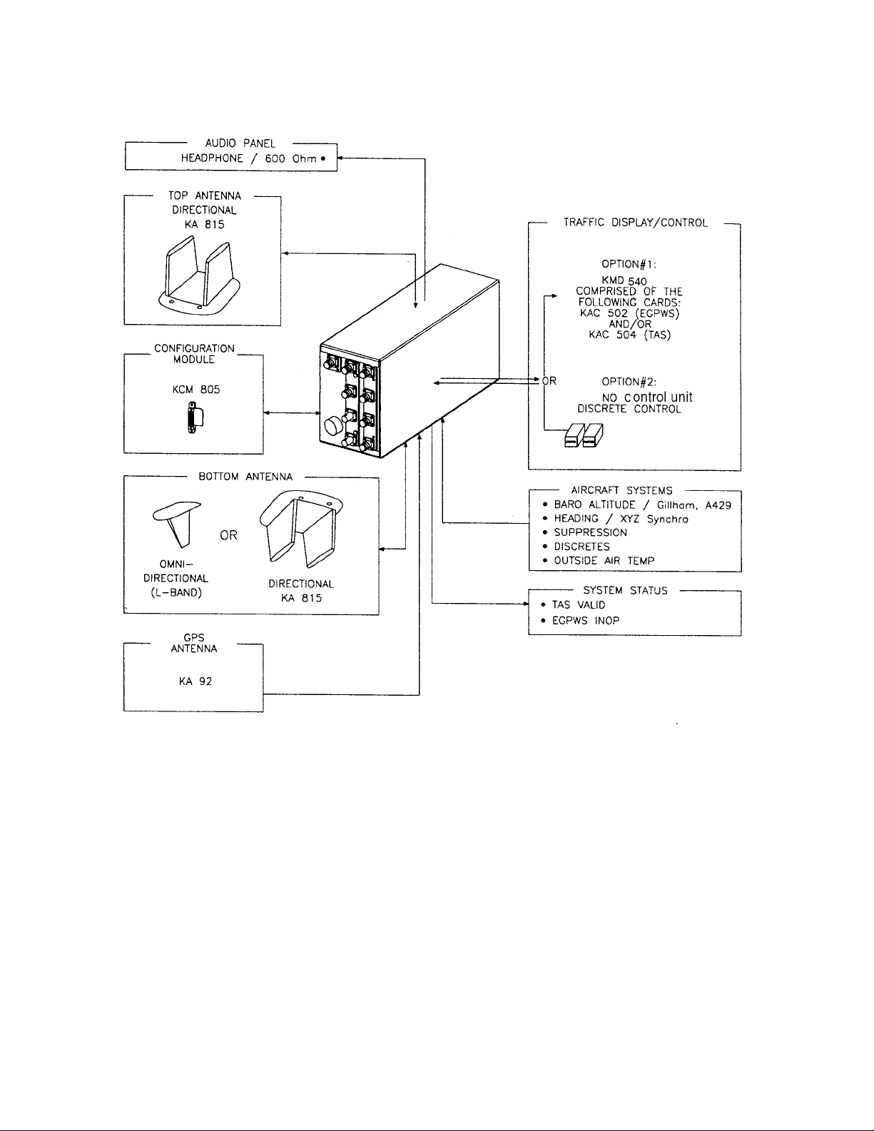
1.3.3 System Components
The KMH 880 Multi-Hazard Awareness System shall be composed of the KMH
820 (TAS/EGPWS Processor), a top mounted directional antenna (KA 815), a bottom mounted antenna (a KA-815 directional antenna which shall provide estimated bearing of target aircraft, or an omni-directional monopole antenna which
will not provide bearing information), a top mounted GPS antenna (KA 92), and a
Configuration Module (KCM 805).
Rev 3, August/2002 10609I03.CDL Page 1-3

B KMH 880/KTA 870
A Multifunctional Display Unit, KMD 540, shall provide control and display of traffic
(via the KAC 504 Traffic Card) and control and display of EGPWS data (via the
KAC 502 Adapter Card). Other displays that are compatible with ARINC 735A
may be used for traffic with this system. See Figure 1-1.
The KTA 870 Traffic Advisory System is similar to the KMH 880 except the KTA
810 Traffic Advisory Unit has only TAS and not EGPWS. The KTA 870 system
does not use a KA 92 GPS antenna. See Table 1-2 and Table 1-3 for a complete
description and part number listing for both systems.
KMH 880 SYSTEM PRIMARY LRUs
System Component LRU Manufacturer/
Model Designator
TAS/GA EGPWS
Processor
Directional Antenna Bendix/King KA 815 TAS Directional Antenna 071-01599-0100
GPS Antenna Bendix/King KA 92 GPS Antenna 071-01553-0200
Configuration Module Bendix/King KCM 805 Configuration Module 071-00112-0100
Control Panel/Display Bendix/King KMD 540 Multi-function Display 066-04035-0X01
Bendix/King KMH 820 Multi-Hazard Awareness
Bendix/King KAC 502 EGPWS Card 071-00158-0211
Bendix/King KAC 504 Traffic Card 071-00166-0411
LRU Description LRU Part Number
066-01175-0101
Processor
066-01175-2101
Table 1-2 KMH 880 LRUs
KTA 870 SYSTEM PRIMARY LRUs
System Component LRU Manufacturer/
Model Designator
LRU Description LRU Part Number
TAS Processor Bendix/King KTA 810 TAS Processor 066-01152-0101
Directional Antenna Bendix/King KA 815 TAS Directional Antenna 071-01599-0100
Configuration Module Bendix/King KCM 805 Configuration Module 071-00112-0100
Control Panel/Display Bendix/King KMD 540 Multi-function Display 066-04035-0X01
Bendix/King KAC 504 Traffic Card 071-00166-0411
Table 1-3 KTA 870 LRUs
Rev 3, August/2002 10609I03.CDL Page 1-4

B KMH 880/KTA 870
In addition to the equipment listed in Tables 1-2 and 1-3, the KMH 820/KTA 810
was qualified with the following displays:
AlliedSignal IVA 81A/C/D TCAS Display 066-50001-XXXX TSO C119a
066-05053-XXXX TSO C8c
066-01171-XXXX
Bendix/King IN 182A EGPWS Display 066-03084-003X TSO C63b
Other displays that are compatible with ARINC 735A may be used to display traffic
with this system. The EGPWS data may also be displayed on Bendix/King and
AlliedSignal weather radar display units. To put traffic on these weather radar displays, the following adapter unit is required:
Bendix/King GC 362A Graphics computer 071-01505-0X03 TSO C105
(To allow traffic on radar displays)
Rev 3, August/2002 10609I03.CDL Page 1-5
B KMH 880/KTA 870
Figure 1-1 KMH 880/KTA 870 System
1.3.4 System Operation
A. EGPWS System
1. EGPWS Modes of Operation
a. Optional Alerting and Warning Parameters
The EGPWS may also be installed in aircraft that do not require FAA
approved TAWS Systems, and may be utilized with an optional set of alerting and warning parameters that are designed especially for smaller piston
aircraft and their normal flight characteristics.
Rev 3, August/2002 10609I03.CDL Page 1-6

B KMH 880/KTA 870
A system configuration making use of these optional curves may require
further showing of compliance for the KMH 820 for installation approval
b. GPS Sensor
The KMH 880 contains an embedded GPS-XPRESS Card sensor that pro-
duces validated navigational position data by continuous signal acquisition
and tracking of the navigational satellite network. The GPS Sensor
receives the C/A code signals transmitted by the satellite network on the L1
frequency of 1575.42 MHz. The sensor has 8 signal processing channels
allowing 8 satellites to be tracked simultaneously. At least 4 satellites must
be in view of the antenna for the sensor to operate. The GPS Sensor uses
data in the satellites’ navigation messages to solve for latitude, longitude,
altitude, horizontal velocity, vertical velocity and current UTC.
GPS Data can also be supplied via the ARINC 743, 743A and RS 232
(KLN 94) interfaces.
A GPS Antenna Splitter could be used in liew of installing another antenna.
B. TAS System
1. TAS Modes of Operation
a. Setup Mode
The system shall be configured using an external PC via the Diagnostic
(RS 232) Interface. Reference the Appendices for the programming proce
dures.
b. Standby Mode
When the Standby mode is selected, the TAS Processor shall disable
surveillance and tracking operations.
The Standby mode may be activated by any of the following: discrete
selection, self-test, aircraft on ground (configuration option), or system failure.
c. Functional Test Mode
When the Functional Test mode is selected, the unit shall be placed into the
Standby mode and the Functional Test portion of BITE shall be performed.
Rev 3, August/2002 10609I03.CDL Page 1-7

B KMH 880/KTA 870
d. TAS Operation (Traffic Advisory) Mode
When the TAS Operation mode is selected, the TAS Processor shall perform
all the surveillance functions and shall provide for the generation of traffic
advisories . The information conveyed in the traffic advisories is intended to
assist the flight crew in sighting nearby traffic.
e. TAS Processor
The TAS Processor shall provide intruder surveillance and tracking, generat-
ing traffic advisories for both Altitude-Reporting and Non-Altitude-Reporting
intruders to display potential conflicts and advisories to the flight crew.
The TAS Processor shall track intruders under surveillance and analyze
range and range rate data, and altitude of the traffic to determine whether that
intruder represents a threat.
The TAS Processor shall also select "proximate traffic" and "other traffic"
intruders to be displayed on the basis of their altitude relative to own aircraft.
The "other traffic" intruders are those that do not qualify to be TA or proximate
traffic but are displayed.
NOTE
Optional (The TAS Processor may be controlled using discrete inputs).
C. Options
1. Display Option
TSO C151a-Class B does not require a display for terrain data, however, if at
all possible, terrain data should be displayed for the aircraft operator. The ter-
rain display greatly improves situational awareness. The EGPWS supports
numerous displays including traditional Radar displays as well as mode mod-
ern MFD’s.
Installations, which include a display, will also need to provide the EGPWS
with range data via ARINC 429 format.
2. Altitude Monitor Option
The EGPWS has the ability to monitor altitude sources and provide caution-
ary messages should an altitude source be suspected of being in error.
Rev 3, August/2002 10609I03.CDL Page 1-8

B KMH 880/KTA 870
This feature compares barometric altitude with GPS altitude and generates a
“Check Altitude” message when an error is detected.
This is a highly recommended option, which can alert a pilot to problems such
as a stuck altimeter or plugged static port. This option requires no additional
hardware and is enabled during the system installation by programming the
configuration module. This feature can provide both audio and display mes-
sages.
3. Outside Air Temperature (OAT) (Recommended)
The EGPWS supports an OAT probe for aircraft operated in cold environ-
ments. Very cold air temperatures cause an increase in the density of the air
mass and can result in barometric altimeter errors, both in sensitive altime-
ters/encoders and blind encoders. Aircraft normally operated in very cold cli-
mates can benefit from the addition of an OAT probe interfaced to the
EGPWS. If the aircraft is equipped with an Air Data Computer which outputs
Digital data with Corrected Altitude on an ARINC 429 port, this can be used
instead of an encoder and external OAT Probe. OAT is programmed into the
configuration module during system installation
1.4 TECHNICAL CHARACTERISTICS
KMH 820 w/o GPS MULTI-HAZARD AWARENESS UNIT
P/N 066-01175-0101
TSO COMPLIANCE:
PHYSICAL DIMENSIONS:
WEIGHT:
Installation Kit
POWER REQUIREMENTS:
See Appendix E
See Figure 2-1
See Figure 2-1
050-03361-0000
Voltage Nominal: +28 Vdc
Range: +22 to +30 Vdc
Current Nominal: 1.3 ± 0.2 A
Max Operating 1.65 ± 0.2 A
Bootup: 3.3 ± 0.5 A
Power 46 ± 2.3 Watts
Table 1-4 KMH 820 w/o GPS Multi-Hazard Awareness Unit Technical Specifications
Rev 3, August/2002 10609I03.CDL Page 1-9

B KMH 880/KTA 870
KMH 820 w/ GPS MULTI-HAZARD AWARENESS UNIT
P/N 066-01175-2101
TSO COMPLIANCE:
PHYSICAL DIMENSIONS:
WEIGHT:
Installation Kit
POWER REQUIREMENTS:
See Appendix E
See Figure 2-1
See Figure 2-1
050-03361-0000
Voltage Nominal: +28 Vdc
Range: +22 to +30 Vdc
Current Nominal: 1.3 ± 0.2 A
Max Operating 1.65 ± 0.2 A
Bootup: 3.3 ± 0.5 A
Power 46 ± 2.3 Watts
Table 1-5 KMH 820 w/ GPS Multi-Hazard Awareness Unit Technical Specification
KTA 810 TRAFFIC ADVISORY UNIT
P/N 066-01152-0101
TSO COMPLIANCE:
PHYSICAL DIMENSIONS:
WEIGHT:
Installation Kit
POWER REQUIREMENTS:
Table 1-6 KTA 810 Traffic Advisory Unit Technical Specifications
See Appendix E
See Figure 2-1
See Figure 2-1
050-03361-0000
Voltage Nominal: +28 Vdc
Range: +22 to +30 Vdc
Current Nominal: 1.15 ± 0.2 A
Max Operating 1.45 ± 0.2 A
Bootup: 2.9 ± 0.5 A
Power 41 ± 2.3 Watts
Rev 3, August/2002 10609I03.CDL Page 1-10

B KMH 880/KTA 870
KCM 805 CONFIGURATION MODULE
P/N 071-00112-0100
TSO COMPLIANCE:
PHYSICAL DIMENSIONS:
WEIGHT:
POWER REQUIREMENTS
Table 1-7 KCM 805 Configuration Module Technical Specifications
TSO COMPLIANCE:
PHYSICAL DIMENSIONS:
See Appendix E
See Figure 2-2
0.1 lbs.
5 Vdc from KMH 820/KTA 810.
KA 815 TRAFFIC ANTENNA
P/N 071-01599-0100
See Appendix E
See Figure 2-3
WEIGHT:
Installation Kit
MOUNTING:
POWER REQUIREMENTS:
MAXIMUM AIRSPEED:
Table 1-8 KA 815 Traffic Antenna Technical Specifications
0.95 lbs.
050-03622-0000
See Figure 2-4 and 2-5
None
335.3 Knots Equivalent Air Speed (EAS)
600 Knots True Air Speed (TAS) and
55,000 feet Not To Be Exceeded (NTBE)
55,000 ft. = 600 knots
Side slip for all the above = 15 degrees
Rev 3, August/2002 10609I03.CDL Page 1-11

B KMH 880/KTA 870
KA 92 GPS ANTENNA
P/N 071-01553-0200
TSO COMPLIANCE:
PHYSICAL DIMENSIONS:
WEIGHT:
Installation Kit
MOUNTING:
POWER REQUIREMENTS
See Appendix E
See Figure 2-6
0.27 lbs.
050-03318-0000
See Figure 2-6
5v supplied by the GPS receiver.
Table 1-9 KA 92 GPS Antenna Technical Specifications
1.5 UNIT AND ACCESSORIES SUPPLIED
1.5.1 TAS Processor Unit
The TAS Processor will provide intruder surveillance and tracking, generating traffic advisories for both Altitude-Reporting and Non-Altitude-Reporting intruders to
display potential conflicts and advisories to the flight crew.
The TAS Processor will track intruders under surveillance and analyze range and
range rate data, and altitude of the traffic to determine whether that intruder represents a threat.
SYSTEM
COMPONENT
TAS/GA
EGPWS
Processor
TAS
Processor
MANUFACTURER/
MODEL
DESIGNER
Bendix/King
KMH 820
Bendix/King
KTA 810
DESCRIPTION PART NUMBER TSO COMPLIANCE
Multi-Hazard
Awareness Processor
TA S
Processor
066-01175-0101
066-01175-2101
066-01152-0101 TSO C147 Class A
TSO C147 Class A
TSO C151a Class B
Table 1-10 KMH 820/KTA 810 Processor Units
Rev 3, August/2002 10609I03.CDL Page 1-12

B KMH 880/KTA 870
1.5.2 Configuration Module
The Configuration Module contains two EEPROMs, one for the TAS Processor
and one for the EGPWS.
The Configuration Module will be remotely mounted in the airframe. It will be
mapped with the Configuration at the installation of the system. An external PC
program will be available to the installer to initialize/program the configuration
module. Reference this Install Manual, Section IV for the programming proce-
dures. A system failure will be annunciated if the configuration module is not programmed, not compatable with the current TAS processor software or if the CRC
read from the module is incorrect.
SYSTEM
COMPONENT
Configuration
Module
1.5.3 Antennas
Full bearing coverage will be achieved by the use of a top and bottom directional
antenna system. The TAS Processor will also be capable of supporting a top
directional and bottom monopole antenna configuration. In the latter configuration,
only intruders being tracked via the top directional antenna will have bearing information.
The antennas will be vertically polarized and cover 360 degrees in azimuth and at
least -10 to +20 degrees in elevation.
SYSTEM
COMPONENT
MANUFACTURER/
MODEL DESIGNER
Bendix/King
KCM 805
Table 1-11 KCM 805 Configuration Module
MANUFACTURER/
MODEL DESIGNER
DESCRIPTION PART NUMBER TSO COMPLIANCE
Configuration Module 071-00112-0100 TSO C147 Class A
TSO C151a Class B
DESCRIPTION PART NUMBER
TSO
COMPLIANCE
Directional
Antenna
GPS Antenna Bendix/King
Omni-Directional
Antenna
Bendix/King
KA 815
KA 92
Dorne and Margolin
Dayton Granger
Sensor System
Comat Industries
TAS Directional
Antenna
GPS Antenna 071-01553-0200 TSO C129
L-Band Antenna DM NI50-9-2*
071-01599-0100 TSO C147
Class A
TSO C66a
10-611-10
565-5366
CI 310
TSO C74
Table 1-12 KA 815/KA 92 Antennas
Rev 3, August/2002 10609I03.CDL Page 1-13

B KMH 880/KTA 870
* This antenna has not been tested for direct effects of lightning and the installer
must determine the suitability of the antenna for the specific installation.
* This Antenna must be a shorted antenna.
CABLE TYPES AND PERMISSABLE GPS CABLE RUN LENGTHS
(8dB allowable loss, including splitter.)
CABLE TYPE
* R/G 142B/U
P/N 024-00002-0000
* R/G 400/U
P/N 024-00051-0060
* These cables use R/G 142/400 style connectors.
Note:
When using Non-KPN or Non-standard P/N cables, connectors etc., the installer has the responsibility of
proving airworthiness.
CABLE RUN LENGTH
(W/O Splitter)
Up to 46 ft.
Up to 46 ft.
Table 1-13 GPS Cable Run Lengths
1.6 INSTALLATION ACCESSORIES SUPPLIED
1.6.1 KMH 820/KTA 810 Installation Kit
SYMBOL PART NUMBER DESCRIPTION [UOM] -0000
010-00068-0026 TERMINALS, CRIMP [EA] 8
J1-J3,
J5-J7, J9
J4, J8 030-00480-0001 CONNECTOR, RF, PLG, BNC,CRIMP (RG 400) [EA] 2
030-01171-0000 CONN SUB-D HSG 9S (FEMALE PINS) [EA] 2
030-00134-0000 CONNECTOR, COAX TNC [EA] 7
030-01157-0011 SOCKET CONTACT, CRIMP [EA] 18
030-01428-0001 EMI HOOD W/ LOCK 9 PIN HIGH DENSITY [EA] 1
030-01464-0000 9 PIN PLASTIC HOOD/W JACKS [EA] 2
030-01451-0000 CONN, SOCKET CONTACT, 15SF D-SUB [EA] 15
030-03447-0001 CONNECTOR HIGH DENSITY PIN FEMALE DSUB [EA] 1
Rev 3, August/2002 10609I03.CDL Page 1-14

B KMH 880/KTA 870
SYMBOL PART NUMBER DESCRIPTION [UOM] -0000
047-12623-0001 INSTALLATION RACK ASSEMBLY [EA] 1
049-00066-0001 ANGLE ROD [EA] 1
057-05944-0015 KMH 820/KTA 810 INSTALL KIT TSO LABEL [EA] 1
089-02161-0022 NUT LOCK 10-24 [EA] 2
089-05907-0008 SCREW, PHP 6-32X1/2 [EA] 4
155-06060-0000 KMH 820/KTA 810 INSTALLATION DRAWING REF
J10 D38999/26FJ35SN 128 PIN I/O CONNECTOR [EA] 1
M85049/38-25N STRAIN RELIEF FOR 128 PIN I/O CONNECTOR [EA] 1
Table 1-14 KMH 820/KTA 810 Installation Kit (P/N 050-03361-0000)
1.6.2 Antenna Installation Kits
SYMBOL PART NUMBER DESCRIPTION [UOM] -0000
155-06059-0000 KA 815 Installation Drawing REF X
M39012/30-0101 Connector, TNC Rt Angle [EA] 4
MS24693-C54 Screw, FHP 100 deg, 8-32x1.00 [EA] 4
MS29513-148 O-Ring [EA] 1
Table 1-15 KA 815 Installation Kit P/N 050-03362-0000
SYMBOL PART NUMBER DESCRIPTION [UOM] -0000
030-00134-0001 Connector, TNC Rt Angle [EA] 1
047-10735-0002 Antenna DBLR Complete [EA] 1
089-05909-0012 Screw PHP 8-32x3/4 [EA] 4
187-01831-0000 Antenna Gasket [EA] 1
155-06019-0000 KA 92 INstallation Drawing REF X
Table 1-16 KA 92 Installation Kit P/N 050-03318-0000
Rev 3, August/2002 10609I03.CDL Page 1-15

B KMH 880/KTA 870
1.6.3 Databases
PART NUMBER DESCRIPTION [UOM]
071- 00167-0101 America’s Database [EA]
071-00167-0102 Atlantic Database [EA]
071-00167-0103 Pacific Database [EA]
Table 1-17 KMH 880 Databases
1.7 ACCESSORIES REQUIRED BUT NOT SUPPLIED
1.7.1 Temperature Probe
The EGPWS is capable of interfacing directly to a standard 500 ohm temperature
probe for aircraft operated in cold environments. Very cold air temperatures cause
an increase in the density of the air mass and can result in barometric altimeter
errors, both in sensitive altimeters/encoders and blind encoders. Aircraft normally
operated in very cold climates can benefit from the addition of an OAT probe interfaced to the EGPWS
SYMBOL PART NUMBER DESCRIPTION [UOM] -0001
137-00042-0001 OAT Probe [EA] 1
MS3106E12S-3S OAT Probe Connector [EA] 1
090-01034-0001 OAT Probe Mounting Kit [EA] 1
010-00068-0016 Crimp Terminal [EA] 1
Table 1-18 Temperature Probe P/N 050-03610-0002
The EGPWS Processor does not require a Temperature Probe input if a Digital Air
Data Computer, with an OAT Label present on the bus, is available as an interface.
1.7.2 GPS Antenna Splitter
To have the flexibility of using an existing KA 92 GPS Antenna, Honeywell offers a
splitter that will greatly simplify the installation procedure. One of the split ports is
DC blocked from the common port so that equipment voltage regulators do not
conflict.
NOTE
Rev 3, August/2002 10609I03.CDL Page 1-16
 Loading...