

Page 1
Fema Regelgeräte
Honeywell AG
Böblinger Straße 17
D-71101 Schönaich
Setting the Switching Point
The interrelation between air speed and resistance change is not linear. In the lower range (low rates of flow) the change of
resistance is very large. In the upper range, the change of resistance at identical changes in the rate of flow becomes increasingly
smaller. When setting the switching point, it must first be determined what change is to be monitored, since some settings result in
certain disadvantages. The following requirements must be taken into consideration:
Low change in the rate of flow in the high flow speed range: the switching point must be chosen very close to the measuring
value of the normal flow, since the change of measuring values is very small when the rate of flow changes. Since the temperature
compensation exhibits a certain amount of delay in comparison to the actual change of temperature, such a setting of the switching
point is possible only with slow changes of temperature.
Low change in the rate of flow in the low flow speed range: the switching point may be selected at a greater distance from the
measuring value of the normal rate of flow, since the changes of the measuring values are larger when the rate of flow changes. A
change in temperature has no effect on the switching behavior.
Large change in the rate of flow: in most cases like this a simple yes/no statement is desired (e.g. ventilator running or ventilator
stopped). Therefore, a larger safety margin may be selected, so that neither temperature changes nor turbulence have any
influence on the switching behavior.
Commissioning of KSL..
Start-up bypass
Jumper set = start-up bypass active for approx. 60 sec. Yellow LED „Time“ is on
Jumper not set = start-up bypass inactive
Connection and commissioning must be performed by properly authorized and qualified personnel!
When commissioning and adjusting the devices, the following procedure is recommended:
• Install and connect the flow controller in accordance with installation instructions and conditions.
• Set jumper for start-up bypass, if required.
• Set trimmer „Sensitivity“ to minimum sensitivity (left limit stop).
• Connect mains voltage. The green LED lights up. If the jumper has been set, the start-up bypass procedure will be executed
(approx. 60 sec.).
• Set nominal rate of flow.
• Slowly turn trimmer „Sensitivity“ clockwise until the yellow LED lights up and the signal output switches. In order to avoid
erroneous switching at low changes of flow, turn the potentiometer slightly past the switching point.
• To check the function of the flow controller, reduce or stop the flow.
• The yellow LED will go off (output relay at RLSW4R is released).
The device is now set to function.
Trouble shooting
Problem Possible Cause Corrective Action
KSL... does not function at all None or wrong mains voltage
KSL... does not detect flow Sensor not installed correctly Check installation conditions
KSL... exhibits changed tripping behavior Sensor heavily contaminated by the
KSL... switches at rapid temperature increase
of the medium
Should you have any further questions, please contact
TELEFON: 0 70 31 / 637-02 y FAX: 0 70 31 / 637-850 y INTERNET: http://www.honeywell.de/fema
BANKEN: Deutsche Bank AG Böblingen 05 / 89 200 (BLZ 600 700 70) y Volksbank Schönbuch eG 784 001 (BLZ 603 628 04)
VORSTAND: Horst Bellwied, Regine Blickwede, Joachim Frosch, Wolfgang Fuchs, Horst Wild, Michael Löffler (stellv.)
VORSITZENDER DES AUFSICHTSRATES: Arnold Günther y SITZ: Offenbach am Main, Amtsgericht Offenbach am Main 5 HRB 6225
22.08.2001
connected
medium
Temperature gradient is outside of
technical specifications
Check mains voltage and connection
Carefully clean sensor with water
Turn potentiometer „Sensitivity“ slightly
further clockwise.
Check temperature gradient of the
system.
Fema Regelgeräte
Honeywell AG
Böblinger Straße 17
D-71101 Schönaich
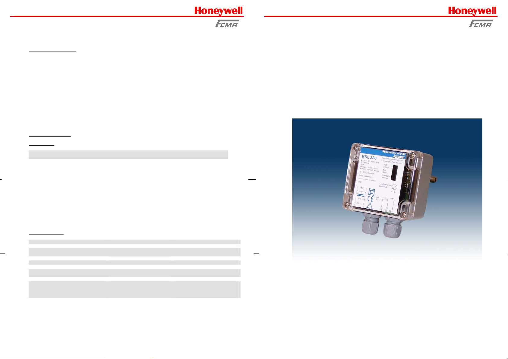
Airflow Controller
Operating Instructions for Airflow Controller
KSL..
TELEFON: 0 70 31 / 637-02 y FAX: 0 70 31 / 637-850 y INTERNET: http://www.honeywell.de/fema
BANKEN: Deutsche Bank AG Böblingen 05 / 89 200 (BLZ 600 700 70) y Volksbank Schönbuch eG 784 001 (BLZ 603 628 04)
VORSTAND: Horst Bellwied, Regine Blickwede, Joachim Frosch, Wolfgang Fuchs, Horst Wild, Michael Löffler (stellv.)
VORSITZENDER DES AUFSICHTSRATES: Arnold Günther y SITZ: Offenbach am Main, Amtsgericht Offenbach am Main 5 HRB 6225
22.08.2001
Page 2
Fema Regelgeräte
Honeywell AG
Böblinger Straße 17
D-71101 Schönaich
The calorimetric airflow controller KSL.. represents an economical alternative to the common pressure pickup. The
installation is simple and quick by means of a flange mount (for channel installation) or by means of the PG7 threaded
connector. The switching point can be selected infinitely with the integrated potentiometer. In case a flow is present, the
switching output is conductive (yellow LED in the unit is on).
Proper use
The flow controllers of the series KSL.. are intended to be used in monitoring of flow speeds of gaseous media within the specified
technical data. A main area of application is heating, ventilating and air conditioning in the field of automated building systems.
Function principle
The flow controllers of the series KSL.. function according to the calorimetric principle. The units are switched when a certain preselected threshold value is reached. In the calorimetric measuring principle a temperature-sensitive resistor is heated. The heating
procedure is achieved by a separate heating resistor. Flow in the medium dissipates heat from the precision resistor, the
temperature of the resistor changes and thus its resistance value. This change is evaluated by the unit. However, not only the flow
speed of the medium has an influence of the dissipated amount of heat, but also its temperature, therefore a relation between flow
and temperature must be established. This is achieved by a second, temperature-dependent precision resistor near the first one.
The second precision resistor (temperature compensation) is not heated and serves to measure the temperature only.
Flow > / = threshold value signal output switched yellow LED „Airflow” is on
Flow < threshold value signal output not switched yellow LED „Airflow” is off
Specifications
Type KSL24 KSL230
Operating voltage 24 V AC/DC 230 V/AC
Voltage tolerance ±10% ±10%
Overvoltage category II II
Signal display, voltage green LED green LED
Power consumption, max. 2 VA 4 VA
Ambient temperature, unit -20..+60°C -20..+60°C
Signal output flow 1 change-over contact 1 change-over contact
Current and contact load capacity 250 VAC, 6 A, 1.5 kVA 250 VAC, 6 A, 1.5 kVA
Switching function at flow relay picks up relay picks up
Signal display at flow yellow LED yellow LED
Start-up bypass 60 s (activated by jumper) 60 s (activated by jumper)
Display of start-up bypass yellow LED yellow LED
Media temperature range -10..+80°C -10..+80°C
Temperature gradient 15 K/min 15 K/min
Switching point adjustable with pot adjustable with pot
Measuring range 0.1 – 30 m/s 0.1 – 30 m/s
Sensor integrated integrated
Immersion depth 130 mm 130 mm
Process connection PG7, mounting flange PG7, mounting flange
Sensor material MS58, nickel-plated MS58, nickel-plated
Pressure resistance 10 bar 10 bar
Type of protection, housing IP65 IP65
Type of protection, sensor IP67 IP67
Contamination class 2 2
Connection 5 terminals, 2.5 mm² 5 terminals, 2.5 mm²
Housing dimensions L 56 mm, W 84 mm, H 80 mm L 56 mm, B 84 mm, H 80 mm
Certification symbols
Accessory Mounting flange Mounting flange
TELEFON: 0 70 31 / 637-02 y FAX: 0 70 31 / 637-850 y INTERNET: http://www.honeywell.de/fema
BANKEN: Deutsche Bank AG Böblingen 05 / 89 200 (BLZ 600 700 70) y Volksbank Schönbuch eG 784 001 (BLZ 603 628 04)
VORSTAND: Horst Bellwied, Regine Blickwede, Joachim Frosch, Wolfgang Fuchs, Horst Wild, Michael Löffler (stellv.)
VORSITZENDER DES AUFSICHTSRATES: Arnold Günther y SITZ: Offenbach am Main, Amtsgericht Offenbach am Main 5 HRB 6225
22.08.2001
0 0
Fema Regelgeräte
Honeywell AG
Böblinger Straße 17
D-71101 Schönaich
Installation Conditions KSL..
To avoid malfunctions, the following points should be observed.
• The tip of the sensor should be as close as possible to the center of the pipe. The transverse hole in the shaft of the sensor
must be within the full flow of the gaseous medium.
• The marking is intended as an assembly aid.
• In case of vertical pipes, the direction of flow should be upwards.
• maintain a free inlet distance of 5xD upstream of the sensor and 3xD outlet distance downstream of the sensor.
• Screw in the flow controller by means of the hexagon of the sensor housing only.
• The flow controller can be installed in any position.
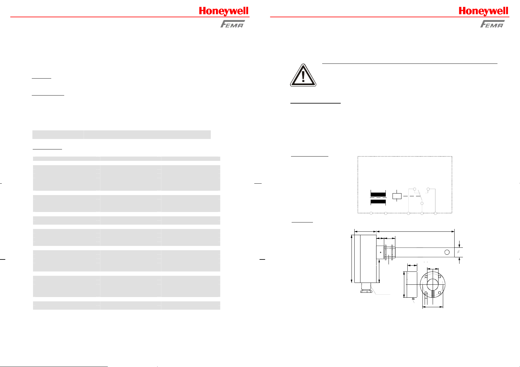
Electrical connection
Dimensions
Connection and commissioning must be performed by properly authorized and qualified personnel!
Connection to mains supply (L, N) must be made by means of a protected isolating switch with the
usual fuses. As a matter of principle, the General VDE Regulations must be complied with (VDE 0100,
VDE 0113, VDE 0160). If the potential-free contact is connected to an extra-low safety voltage, sufficient
insulation must be provided for the connecting cables up to the terminal, since otherwise the double
insulation to the mains voltage side may be impaired. The current load capacity of the potential-free
contact is limited to 6 A. Therefore, the electrical circuit of the potential-free contact must be protected
by a 6.3 A fuse.
ATTENTION!
KSL..
L(+) N(-)
16 15 18
56mm
10
15
80mm
PG7
47mm
140mm
10
15mm
10mm
M16x1,5
45mm
TELEFON: 0 70 31 / 637-02 y FAX: 0 70 31 / 637-850 y INTERNET: http://www.honeywell.de/fema
BANKEN: Deutsche Bank AG Böblingen 05 / 89 200 (BLZ 600 700 70) y Volksbank Schönbuch eG 784 001 (BLZ 603 628 04)
VORSTAND: Horst Bellwied, Regine Blickwede, Joachim Frosch, Wolfgang Fuchs, Horst Wild, Michael Löffler (stellv.)
VORSITZENDER DES AUFSICHTSRATES: Arnold Günther y SITZ: Offenbach am Main, Amtsgericht Offenbach am Main 5 HRB 6225
Fixi ng screw
4.0mm
37 mm
22.08.2001
Flange
 Loading...