

Page 1
Copyright © 2004 Honeywell Control Systems Ltd.
All Rights Reserved EN2B-0004UK07 R0304
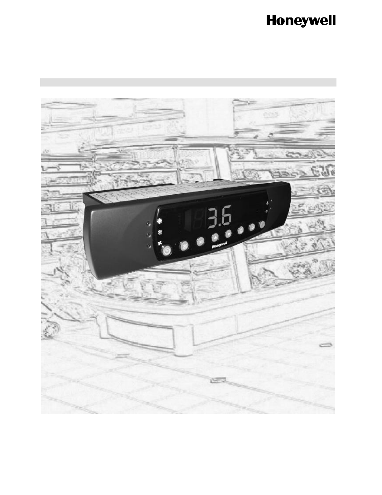
ICON-343C / ICON-363C
REFRIGERATION CONTROLLER
USER GUIDE
Page 2

ICON 343C / 363C US ER GUIDE
EN2B-0004UK07 R0304 1
Trademark Information Genus® is a registered trademark of Honeywell Control Systems Ltd.
Page 3

ICON 343C / 363C USE R GUIDE
2 EN2B-0004UK07 R0304
1. CONTENTS
1. CONTENTS.....................................................................................................................................................................2
2. SAFETY INSTRUCTIONS............................................................................................................................................3
3. GENERAL DESCRIPTI ON...........................................................................................................................................4
4. OPERATOR MODES ....................................................................................................................................................4
5. TECHNICAL SPECIFICATIONS.................................................................................................................................5
6. INSTALLATION .............................................................................................................................................................6
6.1. First Things .............................................................................................................................................................6
6.2. Probes......................................................................................................................................................................6
6.3. Electrical Wiring......................................................................................................................................................6
6.4. Fitting.......................................................................................................................................................................8
6.5. Probe Self Detect...................................................................................................................................................9
7. ICON FRONT PANEL .................................................................................................................................................10
7.1. Functions of the Front Panel..............................................................................................................................10
7.2. Controller front panel LEDs................................................................................................................................10
7.3. Controller front panel keys..................................................................................................................................11
7.4. Functions Of The Keys........................................................................................................................................11
7.5. LED Functions......................................................................................................................................................14
8. CONFIG URATION PARAMETERS..........................................................................................................................15
8.1. Parameter Configuration of the Icon 343C & 363C Controller.....................................................................16
9. REAL TIME CLOCK AND DEFROST SETUP .......................................................................................................23
9.1. Setting and Displaying the Real Time Clock...................................................................................................23
9.2. Setting the Daily Defrost Cycles on the Real Time Clock.............................................................................23
10. CONNECTING TO HONEYWELL GENUS NETWOR K.....................................................................................24
10.1. Icon Controller Identification on Genus® Network........................................................................................24
10.2. Network Logging-On Procedure ......................................................................................................................24
10.3. Network Logging-Off Procedure ......................................................................................................................24
11. PROGRAMMABLE HOTKEY.................................................................................................................................25
11.1. HotKey Uploading Procedure..........................................................................................................................25
11.2. HotKey Downloading Procedure.....................................................................................................................25
12. TROUBLESHOOTING..............................................................................................................................................26
12.1. Alarm Messages ................................................................................................................................................26
12.2. Warning Messages............................................................................................................................................27
13. MAIN TENANCE.........................................................................................................................................................27
14. ABOUT THE OPERATING INSTRUCTIONS .......................................................................................................27
15. NOTES.........................................................................................................................................................................28
Page 4

ICON 343C / 363C US ER GUIDE
EN2B-0004UK07 R0304 3
2. SAFETY INSTRUCTIONS
A. Keep this instruction booklet where it can always be easily consulted by
the operator or by maintenance personnel.
B. Before making an intervention or connection of any kind, make sure that
the mains are disconnected both from the instrument and from any
device connected to it.
C. Warning: hot components may be inside the plastic housing of the
controller.
D. No user-serviceable parts are inside the plastic housing of the controller.
E. The controller and any device connected to it must be installed in
compliance with the safety regulations in force. If these regulations are
not complied with during installation, and if our product is not installed in
compliance with the indications given in this instruction booklet, then this
may result in the safety of the controller being comprimised. In
particular, the ambient operating conditions for the controller given in our
technical data must be complied with. Absolutely avoid: water
condensation or excessive humidity, exposure to steam, corrosive or
toxic gases, contact with any type of liquid, and exposure to shocks or
extreme vibrations. Not complying with the above indications could
cause malfunctions and entail unpredictable consequences.
F. This controller is guaranteed by Honeywell to have a specific immunity
level, in compliance with CE regulations, against irradiated and
conducted electromagnetic disturbances. By irradiated electromagnetic
disturbances we recommend to screen the controller with a metal screen
connected to ground. To eliminate, or at least reduce conducted
disturbances, which not only could propagate through the mains but also
through the probes or the connected loads, carry out the electrical wiring
according to the indications given in this instruction booklet. If
necessary, use filters with suitable characteristics for specific
applications and for the detected type of disturbance.
G. If the type of probe to be used will directly touch foodstuffs, make sure
that it is in compliance with the local sanitary and health regulations.
H. The controller has no type of protection for the connected loads, so
these must be protected against short circuits, over-current or overvoltage, excessive temperature, etc., by suitable protective means (such
as fuses, suitable thermo-magnetic circuit breakers, thermal protections,
etc.). At any rate, the electrical power lines that supply both the
controller and any other device connected to it, either directly or through
a transformer, must be manufactured in compliance with the regulations
in force.
I. When the controller is used in appliances where any malfunction of said
controller could cause a form of risk to persons, animals or objects, it is
ABSOLUTELY MANDATORY to provide a suitable protective/safety
device, in addition to the controller, which independently starts to
operate in case of a failure.
J. The controller cannot be used as critical component in life-support
devices or systems without a written approval expressly issued by the
legal representative of Honeywell.
CAUTION
Disconnect the power supply before you begin installing the Icon controller.
Do not reconnect the power supply until you have completed installation.
Page 5

ICON 343C / 363C USE R GUIDE
4 EN2B-0004UK07 R0304
3. GENERAL DESCRIPTION
The Honeywell Icon 300 Series is a microprocessor controlled thermostat,
powered by AC 230 V, 50/60 Hz, and operates with up to three NTC or PT1000
probes (air-on, air-off and evaporator probes), and has up to six relay outputs
(alarm, auxiliary, light, compressor, defrost and fan), and two digital inputs
(doorswitch and auxiliary). Icon 300 series has a RS485 serial line connection
to enable the controller to interface to Honeywell Genus® network.
The Icon 300 series comes in two variants:
Icon 343 (Part Number: ICON-343C)
Icon 363 (Part Number: ICON-363C)
The Icon 300 series can be applied both in cooling and refrigeration
applications and has the following features:
• satisfy the most diverse plant requirements for cooling/refrigeration with its
42 configurable parameters, that can be set very easily and quickly through
the instrument keyboard.
• display the conditioned ambient temperature as well as the alarm messages
that refer to faulty cooling/refrigeration plant functions.
• control the conditioned ambient temperature through weighted average of
the air-on / air-off probes in order to maintain it under a set limit value (main
set point + differential), by activating the compressor to lower said
temperature every time it exceeds the main set point + differential value.
• control the defrost cycles of the cooling/refrigeration plant manually, through
the network or through the programmed mode; in the latter mode it is
possible to set the starting times of up to six daily defrost cycles.
• control the defrost cycle time as well as the successive startup of the
cooling/refrigeration plant fan through the evaporator probe.
• select the Low Humidity mode (with a specific key) which keeps the fan of
the cooling/refrigeration plant running.
4. OPERATOR MODES
The ICON 343C / 363C controller has three operating modes:
A. Stand-by: The controller is not active and OFF is displayed.
B. Programming: In this mode it is possible to set the configurable
parameter values of the thermostat.
C. Normal: In this mode the conditioned ambient temperature is displayed
and the digital outputs, the defrost cycles, and any case / coldroom alarms
are monitored.
Page 6
ICON 343C / 363C US ER GUIDE
EN2B-0004UK07 R0304 5
5. TECHNICAL SPECIFICATIONS
Icon 343C / 363C
Power Supply AC 230Vac 50/60 Hz
Transformer on board AC 230 – 12 V, 50/60 Hz
Door switch input
operates according to customer
requirements. (not on ICON-343C).
Networking Connection RS485 (Honeywell Genus®)
Air-On, air-off and evaporator
probe range
- 55 … + 85 °C / - 67 … + 185 °F
Compressor output SPST relay, AC 240 V 15A (resist.)
Defrost output SPST relay, AC 250 V 8A (resist.)
Fan output SPST relay, AC 250 V 6A (resist.)
Alarm output:
SPDT relay, AC 250 V 4A (resist.) (not
on ICON-343)
ON/OFF (Auxiliary) output
SPST relay, AC 250 V 4A (resist.) (not
on ICON-343)
Light output SPST relay, AC 250 V 6A (resist.)
Internal alarm buzzer
Back-up battery for internal clock 3 V, lithium (non-replaceable)
Display:
four-digit, 14.2 mm high, green LEDs and
four decimal points
Front panel
Keyboard with 8 keys, 1 red signaling
LEDs and 4 green signaling LEDs
Resolution 0.1 or 1 unit
Network Honeywell Genus®
Electrical connections of the inputs
(probes, digital inputs)
through 3-mm screw terminals for 14
AWG, 2.5 mm2 wires
Electrical connections of the
outputs (relays)
Fast-on shrouded spades
Controller dimensions (height x
width x depth)
46mm x 188mm x 68mm
Installation panel mount
Panel cutout dimension 149.5 x 31.5 mm
Housing in self -extinguishing PC/ABS plastic.
Front Panel IP Class IP52
Operating ambient temperature 0…+ 50 °C / 32… 122 °F
Operating ambient R.H. 30…85 % non-condensing
Storage temperature - 20…+ 80 °C / - 4…176 °F
Table 1. Technical Specifications
Honeywell reserves all rights to modify the technical features of its instruments as
well as to discontinue the production of any model without previous notification.
Page 7

ICON 343C / 363C USE R GUIDE
6 EN2B-0004UK07 R0304
6. INSTALLATION
6.1. First Things
The controller must be installed in a place where it is protected from extreme
vibration, impact, water, corrosive gases, steam, etc., and where temperature
and humidity do not exceed the values given in the technical data sheet.
6.2. Probes
We recommend the use of probes such as Honeywell 2k ohm NTC thermistor
temperature probes (Part Number: TP002K).
Both the air-on and air-off probe is to be installed inside the coldroom or
refrigerated display case where it is protected from direct air flow (i.e., far from
fans or doors) so that the average ambient temperature can be measured.
The evaporator probe must be installed in the coldest area between the
evaporator fins, i.e., where the greatest amount of ice will form and far from the
resistances or the area that warms up first during defrosting, in order to avoid
anticipating termination of said defrost cycle.
6.3. Electrical Wiring
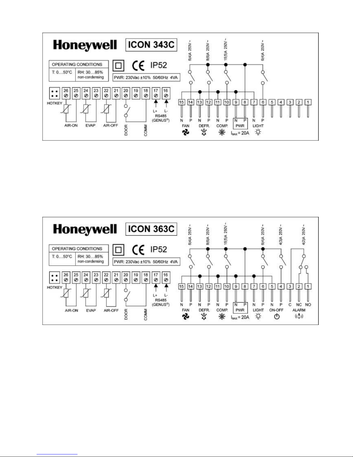
The wiring diagram of the ICON 343C / 363C controller is shown in Figs.1. & 2.
We recommend the protection of the controllers power supply from
electromagnetic disturbances, voltage peaks, etc., especially applications in
particularly critical industrial environments.
This can be done while carrying out the electrical wiring by keeping the
following points in mind:
A. Keep the power output cable s for the compressor, motors, etc. separate
from those for the control part;
B. Keep the probe cables, the controller power cables and the attached load
power supply cables separate and far enough from each other, so they do
not cross or form spirals;
C. Use mains filters to reduce disturbances at the controller power supply, as
well as filters for the loads in order to attenuate disturbances at the
controller relay outputs;
D. If strong radio disturbances are present, screen the entire device with a
metal screen and connect it to ground.
E. Use correct wire gauges to avoid damaging the screw connectors.
Page 8
ICON 343C / 363C US ER GUIDE
EN2B-0004UK07 R0304 7
Fig. 1. – Electrical wiring diagram of the ICON 343C controller
6,7:
8,9:
10,11:
12,13:
14,15:
16,17:
light output
controller power supply
compressor output
defrost output
fan output
RS485 serial line input
18:
19:
20:
21,22:
23,24:
25,26:
comms contact input
not used
door contact input
air-off probe input
evaporator probe input
air-on probe input
Fig. 2. – Electrical wiring diagram of the ICON 363C controller
1,2,3:
4,5:
6,7:
8,9:
10,11:
12,13:
14,15:
alarm output
ON / OFF output
light output
controller power supply
compressor output
defrost output
fan output
16,17:
18:
19:
20:
21,22:
23,24:
25,26:
RS485 serial line input
comms contact input
not used
door contact input
air-off probe input
evaporator probe input
air-on probe input
Page 9
ICON 343C / 363C USE R GUIDE
8 EN2B-0004UK07 R0304
6.4. Fitting
When fitting the controller, leave enough room at the rear to avoid compressing
or excessively bending the cables. The overall instrument dimensions and
panel cut out are given in Figure 3. below.
149.5
31.5
PANEL CUTOUT
188
46
Fig. 3.
– Controller
–
Pane
l-mount
(all dimensions are expressed in mm)
12 8
68
SCREW FIXTURE
Note:
In order to access the screw
fixture (x2) please remove the front
facia, screw controller onto panel
and replace front facia.
WARNING
Disconnect the power supply before you
begin installing the Icon controller. Do
not reconnect the power supply until you
have completed installation.
Please be aware that the relay outputs
are live when controller is powered up.
The contacts are NOT volt free.
Disconnect the power supply before you
begin any maintenance on the Icon
controller.
Page 10

ICON 343C / 363C US ER GUIDE
EN2B-0004UK07 R0304 9
6.5. Probe Self Detect
The Icon 300 series has a feature that allows only the AIR-OFF
probe to be fitted. If this function is used then the controller will not
alarm on any probes that are missing.
Again, this applies to the AIR OFF probe if this is the only probe
that is fitted, and therefore the weighting parameter pair must be
set to 0%.
This function only applies from initial power up of the controller. If
both the AIR -ON and AIR-OFF probes are fitted and the AIR-ON
probe becomes faulty, then the controller will continue to function
using the AIR-OFF probe, and the power to the controller would
have to be cycled off and then on again.
Page 11

ICON 343C / 363C USE R GUIDE
10 EN2B-0004UK07 R0304
7. ICON FRONT PANEL
7.1. Functions of the Front Panel
The front panel of the ICON 343C / 363C controller is shown in Fig. 4. The
front panel includes a four-digit display and four decimal points, a keyboard
with eight keys, and has one red and four green LED alerts.
Fig. 4 Controller Front Panel and Remote Control
With reference to Fig. 3, in Table 1 the LEDs of the front panel are indicated
together with their denomination. In Table 2 the symbols of the front panel keys
are indicated with their denomination.
7.2. Controller Front Panel LEDs
References to Fig. 3
Symbols Description
1
ALARM
2
LOW HUMIDITY
3, 4, 5, 6
•
DECIMAL POINTS 1, 2, 3, 4
7, 8, 9, 10
DIGITS 1, 2, 3, 4
11
COMPRESSOR
12
DEFROST
13
FAN
Table 2. Controller LED’s
Page 12

ICON 343C / 363C US ER GUIDE
EN2B-0004UK07 R0304 11
7.3. Controller Front Panel Keys
References
To Fig. 4.
Symbols Description
14
REAL TIME CLOCK
15
LOW HUMIDITY
16
SET
SET
17
UP
18
DOWN
19
LIGHT
20
DEFROSTING
21
ON/OFF
Table 3. Controller Keys
7.4. Functions of the Keys
The function of the individual keys and combinations thereof are listed below.
Please note that the use of the keys in a combined manner is only possible on
the controller front panel.
DEFROST KEY
• When depressed for 5 seconds, during normal controller functioning,
starts a manual defrost cycle, provided that the temperature measured by
the evaporator probe is below the defrost -end temperature value,
parameter 11 (dFEt). During the manual defrost cycle the DEFROST LED
is switched on.
SET KEY
• When depressed and released, during the normal controller function,
displays SEtP and the main set point value for 5 seconds; it also allows to
you change this value.
• When depressed for 15 seconds, during the normal controller function,
allows you to access the parameter configuration menu (see Section 8.)
and change the parameter settings.
• When depressed and released after having changed the main set point or
a parameter value, enters the new setting.
SET
Page 13

ICON 343C / 363C USE R GUIDE
12 EN2B-0004UK07 R0304
UP KEY
• When depressed while selecting the main set point or parameter settings,
increases the numerical value shown on the display.
DOWN KEY
• When depressed while selecting the main set point or parameter settings,
decreases the numerical value shown on the display.
• When de pressed for 5 seconds when in an alarm state, the acoustic alarm
signal is switched off as well as the alarm signal on the display (provided
the reason for the alarm has been cleared).
LIGHT KEY
• When depressed for 1 second activates or deactivates the light output and
switches the LIGHT KEY LED on or off, if the door of the coldroom is
closed. If the door of the coldroom is open, the LIGHT KEY has no effect
on the ON/OFF function of the coldroom light.
• In “OFF” mode and when the key is depressed for 15 seconds the
controller displays “DEFAULT”, at which time the controller will return to
the factory default settings.
LOW HUMIDITY KEY
• When depressed for 3 seconds, switches the low humidity function on or
off and simultaneously switches the LOW HUMIDITY LED and the LOW
HUMIDITY KEY LED on or off.
• During the low humidity function the fan is always switched on, or is
switched off during defrosting, provided in parameter 20 (FanO), either
option CoF or OnOF have been selected.
• If the low humidity function is switched off, and according to how parameter
20 was set, the fan runs parallel with the compressor or always remains
switched on, except during the defrost and drain-down cycle and until the
evaporator temperature reaches the value set in para meter 18.
ON/OFF KEY
• When depressed for 3 seconds switches the controller on or off. When the
controller is switched off, OFF is displayed.
CLOCK KEY
• When depressed the current time is displayed. As long as this key is
depressed, the display first shows tiME, then the current time, then t1,
followed by the air-on temperature value, then t2, followed by the
evaporator probe temperature value, then t3 followed by the air-off
temperature value then the current time, and so on until the key is
released.
Page 14

ICON 343C / 363C US ER GUIDE
EN2B-0004UK07 R0304 13
UP and SET KEYS
?? When depressed simultaneously during the normal controller operation,
the temperature of the air-off probe (t1) is displayed The display first
shows t1 and then the air-off temperature value until the both keys are
released.
DOWN and SET KEYS
• When depressed simultaneously during the normal controller operation,
the temperature of the evaporator probe (t2) is displayed The display first
shows t2 and then the evaporator temperature value until the both keys
are released.
LIGHT and SET
• When depressed simultaneously during the normal controller operation,
the temperature of the air-on probe (t3) is displayed The display first
shows t3 and then the air-on temperature value until the both keys are
released.
UP and LIGHT KEYS
• When depressed simultaneously for 5 seconds, allows the controller to
log onto the Honeywell Genus® network and communicate.
DOWN and LIGHT KEYS
• When depressed simultaneously for 5 seconds, allows the controller to
log off the Honeywell Genus® network.
UP and DOWN KEYS
• When depressed simultaneously for 10 seconds, locks the keypad.
Display will show ‘access disabled’ in scrolling format. Repeat process to
unclock keypad. Display will then ahow ‘access enabled’.
+ SET
+ + SET
+
+
+ SET
+
Page 15

ICON 343C / 363C USE R GUIDE
14 EN2B-0004UK07 R0304
7.5. LED Functions
ALARM LED
• When switched on, this indicates the presence of an alarm situation. The
alarm situations are accompanied by an intermittent bleeping sound and
are shown with a message on the display.
LOW HUMIDITY LED
• This indicates that the low humidity function is switched on. The fan output
is always switched on, depending on the selection made on parameter 20).
DISPLAY LEDs
• These LEDs show the temperature value of the current time, the values or
the parameter configuration options, the alarm messages or alarm si gnals.
COMPRESSOR LED
• When switched on, but not blinking, indicates that the compressor output is
activated.
• When blinking, indicates that the compressor in anti-short cycle mode
DEFROST LED
• When switched on, but not blinking, indicates that a programmed or
manual defrost cycle is running (the defrost output is activated).
• When switched on, and blinking, indicates that the evaporator is in the
drain-down phase.
FAN LED
• When switched on indicates that the fan output is activated.
COMPRESSOR, DEFROST AND FAN LEDs
?? When flashing in sequence indicates that the controller is in the
programming mode.
+ +
Page 16

ICON 343C / 363C US ER GUIDE
EN2B-0004UK07 R0304 15
8. CONFIGURATION PARAM ETERS
The configuration parameters, their description, and their respective limits or
options as well as their default values are given in Table 4 (page 17).
When the controller is in the normal operating mode it is possible to change
parameter configuration by proceeding the following way:
• Depress the SET key for 15 seconds until the three front panel
COMPRESSOR, DEFROST and FAN LEDs switch on and off in
sequence and SEtP is displayed (this procedure enters the parameter
configuration menu).
• Release the SET key, and when the display shows the previously set
value of the SEtP parameter, change said value by using the UP or
DOWN keys (the change must be carried out within 15 seconds after the
SET key has been released, otherwise the controller returns to the
normal function mode.
• Confirm the newly selected value by depressing the SET key (this must
be done within 15 seconds after changing the SEtP parameter value,
otherwise the controller exits the parameter configuration menu without
changing said value. Once the new parameter value is confirmed it blinks
for 2 seconds, to confirm that the value was accepted and saved by the
controller. After the value is stored the next parameter code is displayed
and, after 2 seconds, its value).
• Change the displayed value of the second parameter and save the new
data by repeating the procedure described in the above two points.
Proceed this way with all the other parameters (once the last parameter
has been saved, the code of the first parameter will again be displayed
and, after 2 seconds, its value. After 15 seconds the controller returns to
the normal function mode.
Please note th at in order to leave a configured parameter value unchanged
during the configuration procedure, depress the SET key when, after having
stored the changed value of the previous parameter, the controller displays
the code or the value of the parameter one wi shes to leave unchanged. In this
manner the controller proceeds and displays the code and then the value of
the next parameter.
The changes made related to time values are only effective after the currently
timed cycles end, while changes regarding other variables are immediately
effective.
Should it be necessary to only change the main set point (parameter SEtP)
during the normal controller function, then this can be done without entering
the parameter configuration menu by proceeding the following way:
• Depress and then release the SET key (SEtP will be displayed and then
current the main set point value).
• Change the displayed main set point value by using the UP or the DOWN
key (the change must be made within 5 seconds after the set point value is
displayed, otherwise the controller returns to the normal function mode
and displays the current message without changing the main set point
value; it is possible to select a main set point value only within the upper
and lower limits, set respectively in para meters 3 and 4).
• Confirm the new value by depressing and then releasing the SET key (this
must be done within 10 seconds after completing the previous operation,
otherwise the controller will return to the normal functioning mode without
changing the main set point value; once the new set point value is
confirmed it blinks for 2 seconds, to validate that it was accepted and
saved by the controller, after which it is replaced on the display by the
current message).
Page 17

ICON 343C / 363C USE R GUIDE
16 EN2B-0004UK07 R0304
8.1. Parameter Configuration of the Icon 343C & 363C Controller
No. Code
Limits/options
[default values]
Resolution
Description
1 SEtP
LSPL…HSPL
[0]
1/0.1 °C (°F)
Main set point: when the compressor is
switched on to reduce the conditioned ambient
temperature, this parameter sets the
temperature value of said conditioned ambient,
which, once it is reached, will switch off the
compressor.
2 HySt
0.1…20.0 °C
0.1…68.0 °F
[2]
1/0.1 °C (°F)
Differential or Hysteresis: when the
compressor is switched off and the conditioned
ambient temperature rises , this parameter sets
the maximum temperature increase with
respect to the main set point, which, once it is
exceeded, will switch on the compressor to
reduce the temperature.
3 LSPL
-55…HSPL °C
-67…HSPL °F
[-40]
1/0.1 °C (°F)
Lower set point limit : this parameter fixes the
lower set point limit value.
4 HSPL
LSPL…+50 °C
LSPL…+122 °F
[50]
1/0.1 °C (°F)
Upper set point limit: this parameter fixes the
upper set point limit value.
5 ACyt
0…999 s
[120]
1 s
Anti cycling time: this parameter fixes the
time interval which starts when the compressor
is switched off and during which it is not
possible to switch it on, in order to allow the
internal refrigeration circuit pressures to
stabilize.
6 HtAd
0…50 °C
0…122 °F
[10]
1/0.1 °C (°F)
High temperature alarm differential: this
parameter fixes the temperature increase of the
conditioned ambient temperature with respect
to the main set point (1), which, when
exceeded, causes the controller, after ALdy
minutes (8), to activate the alarm output, the
intermittent acoustic alarm signal, and displays
the ALHt alarm message, which alternates with
the conditioned ambient temperature value,
provided that during time interval ALdy (8), the
ambient temperature always remains above
SEtP+HtAd
7 LtAd
0…50 °C
0…122 °F
[10]
1/0.1 °C (°F)
Low temperature alarm differential: this
parameter fixes the temperature decrease of
the conditioned ambient temperature with
respect to the main set point (1), which, when
exceeded, causes the controller, after ALdy
minutes (8), to activate the alarm output, the
intermittent acoustic alarm signal, and displays
the ALLt alarm message, which alternates with
the conditioned ambient temperature value,
provided that during time interval ALdy, the
ambient temperature always remains below
SEtP-LtAd.
Table 4. Parameters
Page 18

ICON 343C / 363C US ER GUIDE
EN2B-0004UK07 R0304 17
Parameter Configuration of the Icon 343C / 363C Controller (continued)
No Code
Limits/options
[default
values]
Resolution Description
8 ALdy
0…99 min
[10]
1 min
Low and high temperature alarm delay: this
parameter fixes the time interval in minutes
between the moment in which the conditioned
ambient temperature exceeds the value
SEtP+HtAd (1, 6) and the moment the ALHt
alarm signal is given, provided that during this
time interval, the ambient temperature always
remains above SEtP+HtAd.
Likewise it fixes the time interval in minutes
between the moment in which the conditioned
ambient temperature drops below the value
SEtP-LtAd (1, 7) and the moment the ALLt alarm
signal is given, provided that during this time
interval, the ambient temperature always remains
below SEtP-LtAd.
9
dCSt
1…999 h
[4]
1 h
Time interval between defrost cycles: this
parameter fixes the time interval between the
beginning of a defrost cycle and the beginning of
the next one.
When the defrost cycle is regulated by this
parameter (dCSt), counting of the time interval
between defrost cycles restarts from zero, every
time a defrost cycle is started manually.
During the defrost cycle the settings in parameter
dIdF (22) are displayed.
Please remember that the value set in this
parameter must be greater than the maximum set
interval between two defrost cycles start times set
in parameters tIN1…tIN6.
10 dFCt
1…999 min
[30]
1 min
Maximum defrost cycle time: this parameter
fixes the maximum defrost cycle time, provided
the evaporator defrost-end temperature is not
reached, which is set in parameter dFEt (11), or
an evaporator probe failure occurs.
11 dFEt
-55…+50 °C
-67…+122 °F
[10]
1/0.1 °C (°F)
Defrost-end temperature: this parameter fixes
the evaporator temperature, which, when
reached, ends the defrost cycle. For security
purposes, defrosting ends after the time set in
parameter dFct (10) ends.
12 dFdL
0…99 min
[10]
1 min
Delay of real defrost-end temperature display
:
this parameter fixes the tim e interval, that starts
at the end of a defrost cycle (including draindown time), and during which the controller
displays the last temperature value shown before
the current defrost cycle started, provided the real
temperature value of the conditioned am bient is
higher than said value.
If not, and in any case at the end of the above
mentioned time interval, the controller will again
display the real ambient temperature.
Page 19

ICON 343C / 363C USE R GUIDE
18 EN2B-0004UK07 R0304
Parameter Configuration of the Icon 343C / 363C Controller (continued)
No. Code
Limits/options
[default values]
Resolution Description
13 OFP1
-20…+20 °C (°F)
[0]
1/0.1 °C (°F)
Air-off probe offset: this parameter
fixes the positive or negative correction
to be made of the value measured by
the air-off probe in order to
compensate for measurement errors.
14 OFP2
-20…+20 °C (°F)
[0]
1/0.1 °C (°F)
Evaporator probe offset: this
parameter fixes the positive or
negative correction to be made of the
value measured by the evaporator
probe in order to compensate
measurement errors.
15 OFP3
-20…+20 °C (°F)
[0]
1/0.1 °C (°F)
Air-on probe offset: this parameter
fixes the positive or negative correction
to be made of the value measured by
the air-on probe in order to
compensate for measurement errors.
16 PAir
0…100%
[50]
1%
Control Temperature Weighting:
This parameter fixes the value of the
wighted average of the air-on and airoff probes. Set to zero (0) for 100%
Air-off or set to 100 for 100% Air-on.
17 SErC
0…9999 h
[0]
1 h
Filter maintenance interval time
(service): This parameter indicates
the number of working hours of the fan
which, when reached, will generate the
MSEr message on the display,
accompanied by the sound of the
buzzer, three consecutive times. This
message means maintenance of the
fan filter is required.
This message is repeated in 1-minute
intervals until deactivated by setting
parameter SerC to 0. When the filter
maintenance intervention is terminated
one can set a new interval time for the
following maintenance intervention.
18 FAnt
-55…+50 °C
-67…+122 °F
[0]
1/0.1
Fan startup temperature at
controller start-up and after defrost
cycle: this parameter determines the
evaporator temperature value
measured by the evaporator probe.
Below this value the fan is switched on
after delay time in parameter Fand
(19).
The Fand parameter is de-activated
while the controller operates in low
humidity mode. The fan is always
switched on, except during defrosting
(see parameter 20, FanO).
Page 20

ICON 343C / 363C US ER GUIDE
EN2B-0004UK07 R0304 19
Parameter Configuration of the Icon 343C / 363C Controller (continued)
No. Code
Limits/options
[default values]
Resolution Description
19 FAnd
0…99 min
[2]
1
Fan start delay at controller startup
and after defrost cycle : this parameter
fixes the time interval that starts at
controller start-up or at the end of a
defrost cycle (including drain-down
time), during which the fan must remain
switched off in order to not introduce
warm and humid air into the conditioned
ambient air.
At the end of said time interval, the fan
will be switched on either immediately, if
the evaporator probe is defective, or
when the evaporator temperature drops
and reaches the value set in parameter
18 (Fant).
The Fand parameter is de-activated
while the controller operates in the low
humidity mode. The fan is always
switched on, except during defrosting
(see parameter 20, FanO).
20 FAnO
Con, CoF, OnOn
OnOF
[OnOn]
Fan operating mode: this parameter
fixes the type of fan operating mode.
If the Con option is selected, then the
fan operating mode is linked to that of
the compressor, provided the system is
not operating in the low humidity mode.
The fan is always switched on when the
system is operating in the low humidity
mode.
If the CoF option is selected, then the
fan operating mode is linked to that of
the compressor, provided the system is
not operating in the low humidity mode.
The fan is always switched on, except
during the defrost cycle, when the
system is operating in the low humidity
mode.
If the OnOn option is selected, then the
fan is always switched on, except during
the defrost cycle and thereafter for the
time set in parameter 19 (Fand), until the
temperature has reached the value set
in parameter 18 (Fant), provided the
system is not operating in the low
humidity mode. The fan is always
switched on when the system is
operating in the low hu midity mode.
If the OnOF option is selected, then the
fan is always switched on, except during
the defrost cycle and thereafter for the
time set in parameter 19 (Fand). Until
the temperature has reached the value
set in parameter 18 (Fant), provided the
system is not operating in the low
humidity mode. The fan is always
switched on, except during the defrost
cycle, when the system is operating in
the low humidity mode.
Page 21

ICON 343C / 363C USE R GUIDE
20 EN2B-0004UK07 R0304
Parameter Configuration of the Icon 343C / 363C Controller (continued)
No. Code
Limits/options
[default values]
Resolution Description
21 CodF
OFF, On
[OFF]
Compressor operating mode during the
defrost cycle: this parameter determines
the compressor function mode during a
defrost cycle, i.e., always switched off when
the OFF option is selected, or always
switched on when the On option is selected.
22 DIdF
REAL, dEF, LAST
[dEF]
Displayed message during a defrost
cycle: this parameter indicates the
message to be displayed during a defrost
cycle (including the drain-down time), i.e.,
the real conditioned ambient temperature if
option REAL is selected, dEF if option dEF
is selected, or the last conditioned ambient
temperature measured before the defrost
cycle if option LAST is selected.
23 drIP
0…99 min
[2]
1 min
Drain-down time: this parameter fixes the
time interval, which starts when a defrost
cycle ends, and during which the
compressor is switched off to allow for
optimized drying of the evaporator.
24 Ptyp
NTC, RTD
[NTC]
This parameter determines the type of
probe connected to the controller; option
NTC (default) is for NTC 2K probes,
whereas option RTD is for PT1000 probe.
25 RESo
Int, Dec
[Int]
Resolution: this parameter determines with
which resolution the temperature value is to
be displayed, i.e., 1 if option Int is selected,
or 0,1 if option Dec is selected.
26 UnIt
CELS, FAHr
[CELS]
Unit of measure: This parameter sets the
unit of measure of the temperature, i.e., °C
if the option CELS is selected, or °F if the
option FAHr is selected.
27 COPF
OFF, ON, CYC
[CYC]
Compres
sor function during probe
failure: this parameter fixes the compressor
operating mode during a conditioned
ambient temperature probe failure.
If option OFF is selected, the compressor is
switched off and remains like that until the
failure has been repaired; if option ON is
selected, the compressor is switched on
and remains like that until the probe failure
has been repaired; if option CYC is
selected, the compressor – as soon as the
failure occurs – alternates the time interval
set in parameter 28 (CoOF), during which it
remains switched off, with the time interval
set in parameter 27 (CoOn), during which it
remains switched on, and so on until the
failure has been repaired.
Page 22

ICON 343C / 363C US ER GUIDE
EN2B-0004UK07 R0304 21
Parameter Configuration of the Icon 343C / 363C Controller (continued)
No. Code
Limits/options
[default values]
Resolution Description
28 COOn
1...99 min
[2]
1 min
Compressor on-time during probe
failure: this parameter fixes the time
interval that alternates with the time set in
parameter 28 (CoOF), during which the
compressor must remain switched on during
a probe failure, provided option CYC is
selected in parameter 26 (CoPF).
29 COOF
1…99 min
[5]
1 min
Compressor off-time during probe failure
:
this parameter fixes the time interval that
alternates with the time set in parameter 27
(CoOn), during which the compressor must
remain switched off during a probe failure,
provided option CYC is selected in parameter
26 (CoPF).
30 dOrS
nO, nC
[nO]
Door switch: this parameter determines the
position of the door switch, that corresponds
with when the door is closed. If dorS = nO, the
door is closed when the switch is normally
open. If dorS = nC, the door is closed when
the switch is normally closed.
31 dSFU
nOCy, FAOF,
COOF, FCOF
[FAOF]
Controller functions when door is open:
this parameter determines the controller
function when the door is open.
If the option nOCY is selected the controller
continues to function normally.
If the option FAOF is selected then the
controller switches off the fan two seconds
after the door has been opened and for as long
as the door remains open.
If the option COOF is selected then the
controller switches off the compressor one
minute after the door has been opened and for
as long as the door remains open.
If the option FCOF is selected then the
controller switches off the fan two seconds
after the door has been opened, and the
compressor one minute after the door has
been opened, and both for as long as the door
remains open.
Whichever option is selected, as long as the
door remains open the controller displays the
message “door” that alternates with the current
message.
32 rHPb
EnAb
dISA
[dISA]
Low humidity push -button
activation/deactivation:
This parameter enables or disables the High
Humidity key, according to the option that
was selected, i.e., EnAb or dISA.
33 tINE
00.00…23.59
[12.00]
1 min
Real time: this parameter allows to set the
current time in the HH:MM format.
Page 23

ICON 343C / 363C USE R GUIDE
22 EN2B-0004UK07 R0304
Parameter Configuration of the Icon 343C / 363C Controller (continued)
No. Code
Limits/options
[default values]
Resolution Description
34 tIN1
35 tIN2
36 tIN3
37 tIN4
38 tIN5
39 tIN6
00.01…23.59
- - - -
- - - -
- - - -
- - - -
- - - -
- - - 1 min
1st, 2nd,…,6th defrost cycle starting
times: in this parameter up to six defrost
cycle starting times can be set, or the
same can be disabled (option - - - - ).
A given defrost cycle not only doesn’t
occur when disabled, but is also
deactivated, should its starting time be
during another enabled defrost cycle
(manual defrosting), or during a time alarm
(ALti).
If the various defrost cycle start times are
not set in the increasing order of the
parameters (e.g., TIM1=18.30,
TIM2=09.27), then the execution of the
defrost cycles will not respect the order of
said parameters, but will respect the
increasing order of real time.
Every selected defrost cycle ends when
the evaporator reaches the temperature
value set in parameter 11 (dFEt), or when
the time set in parameter 10 (dFct) ends.
During the defrost cycle the display shows
the settings made in parameter 22 (dIdF).
40 DFst
DFSt = rEM
(remote)
DFS t= Loc (local)
Local or Remote Defrost Start Modes
DFSt for defrost start mode that defines
the selection between Local or Remote
defrost operation; if DFSt= rEM the
defrost is initiated only when a net work
command is issued by the Supervisor (or
Genus® Front -End system); if DFSt= Loc
the defrost is controlled by the local
timing set by the parameters
TIN1….TIN6
41 StUb
0...99
[0]
Stub Number
Number given to identify refrigeration
stub from 0…99 when connected to, and
viewed from, a Genus® network
42 CASE
0...9, A,B,C,D, E,
F,G,H,I,L,P,T,U,Y
[0]
Case number
Number given to identify refrigeration
case from 0…9…A…Y when connected
to, and viewed from, Genus® network.
Page 24

ICON 343C / 363C US ER GUIDE
EN2B-0004UK07 R0304 23
9. REAL TIME CLOCK AND DEFROST SETUP
9.1. Setting and Displaying the Real Time Clock
The Real Time Clock (RTC) operates on a 24 hour cycle (00:00…23:59)
The current time set in the RTC can be displayed by depressing and holding the
CLOCK key. The display will show the standard format (24 hours) of: HH.MM
(hours. minutes)
Procedure:
1. To set the Real-Time clock press and hold the SET Key for 15 seconds until
the three front panel COMPRESSOR, DEFROST and FAN LEDs switch on
and off in sequence and SEtP is displayed (with this procedure one enters
the parameter configuration menu).
2. Repeatedly press the SET key until ‘tINE’ is displayed followed by current
time value. Use the UP and DOWN arrows to set clock as required.
3. Press SET to confirm new value.
9.2. Setting the Daily Defrost Cycles on the Real Time Clock
It is possible to set -up 6 defrost cycles per day on Icon models: ICON-343C &
ICON-363C.
The time parameters regarding this function are: tIN1, tIN2, tIN3, tIN4, tIN5 & tIN6
Notes:
1. In order to activate a defrost cycle it is necessary to set the defrost cycle
starting time in at least one of the parameters (tIN1, tIN2, tIN3, tIN4, tIN5 or
tIN6)
2. To be recognized as valid the time must be set in the format of HH.MM, (24
hours)
3. If parameters tIN1…tIN6 are set to - - . - - then function is DISABLED.
Procedure:
1. To set the timed defrost press and hold the SET Key for 15 seconds until
the three front panel COMPRESSOR, DEFROST and FAN LEDs switch on
and off in sequence and SEtP is displayed (with this procedure one enters
the parameter configur ation menu).
2. Repeatedly press the SET key until ‘tIN1’ is displayed followed by current
value. Use the UP and DOWN arrows to set defrost start time as required.
3. Press SET to confirm new value.
4. Repeat steps 1 to 3 for tIN2…tIN6.
Important:
With regard to parameter dCSt, (time interval between defrost cycles), please
remember that the value set in said parameter (dCSt) must be greater than the
maximum set interval between two defrost cycles start times set in parameters
tIN1…tIN6.
Example: tIN1 = 05.00 tIN2 = 11.30
TIN3 = 15.30 tIN4 = 23.50
TIN5 = - -.- - tIN6 = - -.- -
Therefore: dCSt > 18 hours 50 mins.
Page 25

ICON 343C / 363C USE R GUIDE
24 EN2B-0004UK07 R0304
10. CONNECTING TO HONEYWELL GENUS NETWORK
10.1. Icon Controller Identification on Genus® Network
Icon has to be given a name (alias) in order to log onto the Genus® network. The
following naming convention is required for Genus network identification and
defrost capabilities.
The Icon controller name is displayed as ‘ICXX-Y’ on Genus network. Where ‘XX’
is the StUB number and ‘Y’ is the CASE number.
A stub number ‘XX’ represents the refrigeration section where the Icon controller
is situated within the supermarket. A case number ‘Y’ represents the case within
the stub.
10.2. Network Logging-On Procedure
1. Disconnect or ensure that the controller is not logged on the network by
depressing the buttons LIGHT+DOWN for 5 sec: the controller will display
OFFLINE
2. Connect Genus® network cable to Genus® socket at rear end of the Icon
controller. OBSERVE POLARITY
3. Set the StUb parameter between 0..99
4. Set the CASE parameter between 0…9,A,B,C,D,E,F,G,H,I,L,P,T,U,Y
5. Enable the controller to communicate on the network by depressing the
buttons LIGHT+UP for 5 sec: the controller will display ONLINE
10.3. Network Logging-Off Procedure
1. To log off from the Genus network depress the buttons LIGHT+DOWN for
5 seconds, the controller will display OFFLINE
Page 26

ICON 343C / 363C US ER GUIDE
EN2B-0004UK07 R0304 25
11. PROGRAMMABLE HOTKE Y
The Icon controller has an optional programmable HotKey (Part Number: ICONKEY3) When the controller is in OFF mode i.e. when it is non-activated and displays
the message “OFF”, it is possible to upload the parameter configurations of the
controller to the HotKey, or vice-versa, to download parameter configurations from
the HotKey to the controller.
11.1. HotKey Uploading Procedure
To upload the parameter configuration from the controller to the HotKey, proceed in
the following manner.
1. Connect the HotKey to the HotKey connector on the rear of the controller (Note:
the HotKey is orientated where the Hotkey main body is vertically inserted with
the keyring hole below the main body of the Icon controller. Failure to observe
this orientation instruction will result in controller malfunction)
2. Press the DEFROST key for 15 seconds until the ”PrOG” message appears on
the display.
3. Press the UP key until the “n-SA” message appears on the display.
4. Press the SET key for at least 5 seconds until the “yES” message, the “-rST”
message (meaning the data is being uploaded) and after that the “OFF” message
appears on the display.
5. The HotKey can now be removed.
11.2. HotKey Downloading Procedure
To download the parameter configuration from the HotKey to the controller, proceed
in the following manner.
1. Connect the HotKey to the HotKey connector on the rear of the controller. (Note:
the HotKey is orientated where the Hotkey main body is vertically inserted with
the keyring hole below the main body of the Icon controller Failure to observe
this orientation instruction will result in controller malfunction)
2. Press the DEFROST key for 15 seconds until the ”PrOG” message appears on
the display.
3. Press the DOWN key until the “n-rd” message appears on the display.
4. Press the SET key for at least 5 seconds until the “yES” message, the “-rST”
message (meaning the data is being downloaded) and after that the “OFF”
message appears on the display.
5. The HotKey can now be removed.
6. If for any reason the download procedure from the HotKey to the controller does
not work correctly, or is not possible because the HotKey is not enabled, after
pressing the SET key the “Err” message will appear on the display (indicating
that the data was not transferred) and will be followed by “-rST” and “OFF”.
7. If the Icon is connected to the Honeywell Genus® network, manually re-configure
controller parameters StUb and CASE to reflect new address. Also manually reconfigure DFst (see note below).
Note: Parameters DFst (local or remote defrost) will be automatically set to ‘LOC’
(local) , StUb (stub number), CASE (case number) are automatically set to ‘0’
(default) when Hotkey download to new controller is complet e. This ensures that
there is no conflict with 2 or more controllers having the same network address.
Reconfigure these parameters to create new address for controller as well as
network logging status. E.g. StUb = 14, CASE = 5.
Page 27

ICON 343C / 363C USE R GUIDE
26 EN2B-0004UK07 R0304
12. TROUBLESHOOTING
The ICON controller is able to recognize and to signal seven types of alarm
situation. Each alarm type has a corresponding alarm message and actions
that are made by the controller (see Table 5).
The alarm messages are displayed and alternate with the current di splayed
value; they are also accompanied by an intermittent audible signal (buzzer).
Once the cause for the alarm has been eliminated, the corresponding alarm
message continues to be displayed and is accompanied by the buzzer.
In case of an ‘Alti’ alarm, once the cause has been eliminated, it is necessary to
reset both the current time and the various defrost cycle starting times
(parameter 38 – tINE…. tIN1, tIN2,.., tIN6).
When DOWN key is depressed for 5 seconds when in an alarm state, the
acoustic al arm signal is switched off as well as the alarm signal on the display
(provided the reason for the alarm has been cleared).
12.1. Alarm Messages
Alarm
message
Cause Controller intervention
ALP1
Interruption or short circuit of the
AIR-OFF probe.
Alarm output active
Compressor output according to parameters
COPF, COOn & COOF (26, 27, 28)
Other outputs not modified
ALP2
Interruption or short circuit of the
evaporator probe.
Alarm output active
Defrost output as set in parameter 10 (dFCt)
Fan start delay as set in parameter 19
(Fand)
Other outputs not modified
ALP3 Interruption or short circuit of the
AIR-ON probe.
Alarm output active
Other outputs not modified
ALHt The temperature of the conditioned
ambient exceeds SEtP+HtAd (1, 6)
and therefore remains above
SEtP+HtAd for the time set in
parameter 8 (ALdy)
Alarm output active
Other outputs not modified
ALLt The temperature of the conditioned
ambient drops below SEtP-LtAd (1,
7) and therefore remains below
SEtP-HtAd for the time set in
parameter 8 (ALdy)
Alarm output active
Other outputs not modified
ALti Internal clock failure or clock back-up
battery exhausted or defective.
Alarm output active
Defrost output as set in parameters 9,11,10
(dCSt, dFEt or dFCt)
ALEE Loss of EEPROM data Alarm output active. The instrument
functions with the default parameters given
in Table 4
Table 5. Alarm Messages
Page 28

ICON 343C / 363C US ER GUIDE
EN2B-0004UK07 R0304 27
12.2. Warning Messages
As well as the alarm signals, the ICON controller can also display four warning
messages as given in the table below.
Warning Messages Meaning
dEF Defrost cycle activated
door Coldroom door is open
FiLt Filter requires maintenance
OFF Controller is in the stand-by mode
Table 6. Warning Messages
13. MAINTENANCE
Clean the instrument front panel with a soft cloth, dampen ed with soapy water.
We recommend not to use abrasive detergents or detergents that contain
solvents, since they could damage the instrument; also, do not splash water or
any other liquid directly on the instrument.
All repairs on the controller must be carried out by authorized personnel.
Opening the instrument housing or tampering with the controller automatically
voids the warranty.
14. ABOUT THE OPERATING INSTRUCTIONS
These operating instructions are to be considered part of our product and are
therefore to be kept with proper care until the product itself is disposed of.
The user can directly request new operating instructions from Honeywell,
should those supplied have been damaged or lost.
Honeywell reserves the right to modify product features and/or to up-date the
operating instructions at any time, without giving prior notice and without the
obligation to up-date previously issued versions.
The user can request possible up-dates or integrations directly from Honeywell;
he/she may also request further information about the product and in turn make
proposals on how to improve these operating instructions.
The information included in these operating instructions shall serve to illustrate
the use of the product as foreseen in the application, to list its technical
features, to supply information about its installation and regulation, to prescribe
maintenance procedures, to list residual risks, etc.
Honeywell therefore assumes no responsibility deriving from the improper use
of its product or use by incompetent personnel, incorrect installation, faulty
power supply, serious lack of prescribed maintenance, non-authorized
modifications or interventions, the use of spare parts that are either not original
or not specific for this model or not fully complying with the operating
instructions.
Page 29

ICON 343C / 363C USE R GUIDE
28 EN2B-0004UK07 R0304
15. NOTES
Page 30

ICON 343C / 363C US ER GUIDE
EN2B-0004UK07 R0304 29
Page 31

ICON 343C / 363C USE R GUIDE
30 EN2B-0004UK07 R0304
Page 32

Automation & Control Solutions
Cooling & Refrigeration
Newhouse Industrial Estate
Motherwell
Lanarkshire ML1 5SB
Phone: (44) 01698 481698
Fax: (44) 01698 481699
www.honeywell.com/cooling
Subject to change without notice. Printed in United Kingdom
EN2B-0004UK07 R0304
 Loading...