

Page 1
OPERATION MANUAL
Built-in x35 ZOOM / WDR
High Resolution AUTO FOCUS CAMERA
HZC-855NX/PX Series
READ AND KEEP THIS OPERATION MANUAL
Page 2
CAUTION:
CAUTION
RISK OF ELECTRIC SHOCK
DO NOT OPEN
TO REDUCE THE RISK OF ELECTRIC
SHOCK, DO NOT REMOVE COVER
(OR BACK). NO USER SERVICEABLE
PARTS INSIDE.
PREFER SERVICING TO QUALIFIED
SERVICE PERSONNEL.
Indicate a potentially hazardous situation which if not avoided,
may result in minor or moderate injury. It may also be used to
alert against unsafe practices.
Warning:
This equipment generates and uses radio frequency energy
and if not installed and used properly, I.e., in strict accordance
with the instruction manual, may cause harmful interference
to radio communications. It has been tested and found to comply
with the limits for a Class A computing device pursuant to Subpart
J of Part 15 of FCC Rules, which are designed to provide reasonable
protection against such interference when operated in a commercial
environment.
Warning:
TO PREVENT FIRE OR SHOCK HAZARD, DO NOT EXPOSE THIS
APPLIANCE TO RAIN OR MOISTURE.
-2-
Page 3

CAUTION FOR SAFE OPERATION
1. Water and Moisture
To prevent fire or shock hazard, do not expose this camera
to rain or moisture.
2. Servicing
Do not attempt to disassemble or repair by yourself.
You may be exposed to dangerous voltage or other hazards.
Note that all servicing is qualified service personnel.
Modifications not approved by manufacturer could
void the user's authority to operate the equipment.
3. Power Sources
To prevent electric shocks and risk of hazards, do not use
more than the specified power source.
4. Environment
Do not install too warm or too cold place. Recommended
operation temperature is between -5℃ and 60℃
5. Sunlight
Do not point the camera at the sun. CCD can be damaged.
6. Heavy Shock and Vibration
Do not drop the camera or subject it to heavy shock of
vibration.
7. Install on an Unstable Place
Do not place or install this camera on an unstable place,
stand, tripod, bracket or table. That may cause serious injury
to people or damage to appliance.
8. When operation is incorrect or a malfunction is observed
While operating, if any abnormal condition (strange sound,
smell or smoke) or a malfunction (no pictures, etc.) is
observed, stop using the camera immediately, turn the
power off, then contact your supplier.
9. Cleaning
Turn the power off and wipe off the dirt with a dry softcloth.
If it is extremely dirty, use furniture cleaner to wipe it off.
To clean the lens, use a blower or lens cleaning tissue.
(available from any camera dealer)
10. Do not shoot any source of bright light.
If the objects contain very bright areas, bright vertical or
horizontal lines may appear on the screen. This is called
"smear" , a Phenomenon which often occurs with solid
-state pickups, and is not a malfunction.
11. Damage Requiring service
Unplug the camera from the power source and refer
servicing to qualified service personnel under the following
condition:
a. If the power-supply cord or plug is damaged.
b. If the camera has been exposed to rain or water.
c. If liquid has been spilled, or objects have fallen into the camera.
d. If the camera does not operate normally by following the operating
instructions. Adjust only those controls that are covered by the
operating instructions as an improper adjustment of other controls
may result in damage and will often require extensive work by a
qualified technician to restore the camera to its normal operation.
e. If the camera has been dropped or the cabinet has been damaged.
f . If the camera exhibits a distinct change in performance.
Warranty is not covered in case of natural disaster or wrong
Installation.
-3-
Page 4

CONTENTS
1. Features ---------------------------------------------------------------5
2. Terms & Functions ------------------------------------------------6
3. Installation ------------------------------------------------------------7
4. Camera Control Methods -------------------------------------------8
5. On Screen Display --------------------------------------------------10
6. Specifications ---------------------------------------------------------21
7. Dimensions ------------------------------------------------------------22
Thank you for using our Auto Focus Zoom Color Camera. To get thebest
efficiency, read carefully all instructions in this manual before use, and
keep this manual for reference. If you have any problems with this camera,
contact your supplier to service.
-4-
Page 5

1. Features
Ideal Digital Video Camera for Security
The HZC-855NX/PX Ser. is a compact camera that offers easy system
integration. Coming with the built-in zoom lens, the user can monitor the
scene from variable angle without the extra lens.
With the DSP technology, such intelligent controls as auto iris,
and auto white balance are possible to realize clear detailed picture.
Additionally, through RS-232C, RS422, remote Focus/Zoom operations
are also possible, along with manual control. All these featuresincluding
highly sensitive 1/4-inch CCD make the ideal digital processing CCTV
camera HZC-855NX/PX series more effective surveillance.
Built -in x35 Optical power zoom lens
The HZC-855NX/PX Ser. with highly durable built-in zoom lens offers
auto focus, auto iris , and optical zoom functions enabling the user
to monitor a scene with clarity in any desired angle of view.
With the x35 optical zoom lens, the total zoom can be up to x90 with
x2.5 digital zoom processing.
High Resolution & Sensitivity SONY CCD
The chassis features a highly sensitive 1/4-inch CCD pickup with
approximately 380,000 effective pixels minimizing residual image
and geometric distortion. All images are reproduced with a high
horizontal resolution of 530 TV lines for fine detail.
High Sensitivity with Integration and removal of IR filter
HZC-855NX/PX Ser. has the increased light sensitivity to 0.0005lx
(510 fields, IR Cut Filter ON) through field (frame) integration
technology. With Integration and removal of IR cut filter make more
effective surveillance though low light condition.(HZC-855NX/PX : less
than 0.00001 lx)
Privacy Zone Masking
HZC-855NX/PX Ser. mask the unwanted view for privacy protection
up to 8 zones. Privacy Zone operate with zoom in/out and it increases
the effect of privacy protection.
Remote Control through RS232C, RS422 Interface
Remote control operations are possible through RS232C/RS422
interface for Focus, Zoom control and various functions.
AI / Fuzzy Control Circuit with DSP
Advanced DSP technology automatically adjusts operations such as
Iris , White Balance flexibly adapting to environmental conditions.
Auto Iris : the iris is adjusted so that visual output is kept at a fixed
level, even if brightness of the surrounding changes.
Auto White Balance : color adjustment according to the color
temperature of the light source illuminating the subject.
white balance can be obtained even with fluorescent
lights, halogen lamps or outdoor.
WDR (Wide Dynamic Range)
This is the technology using dual shutters from both dark and bright
areas to be enhanced and displayed vivid video image. While a
conventional image shows white clip caused by the bright spot, WDR
overcomes and solves the obstacle of the white clip problem.
-5-
Page 6
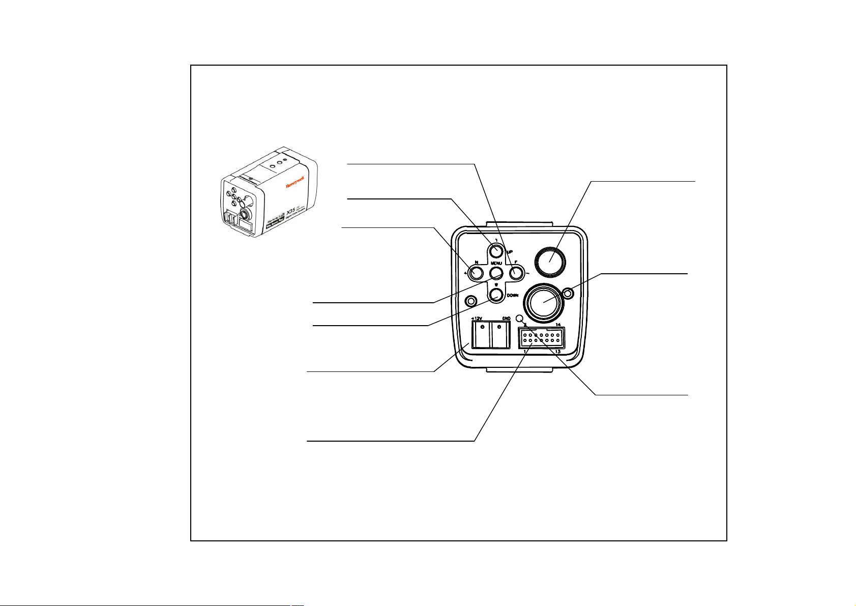
2. Terms & Functions
FAR(-) BUTTON
TELE(UP) BUTTON
NEAR(+) BUTTON
VIDEO OUTPUT
This is the output terminal
for composite video signal .
VIDEO
MENU BUTTON
WIDE(DOWN) BUTTON
POWER INPUT TERMINAL
DC 12V
( Please use a specified adaptor)
CAMERA CONTROL CONNECTOR
This is the 14 pin connector for external
camera controls .
( Refer to 4. CAMERA CONTROL METHODS )
-6-
SVIDEO
This is the output terminal
for separate Y/C signal .
POWER ON LAMP
In power ON state ,
this LED is ON .
S-VIDEO OUTPUT
Page 7
3. Installation
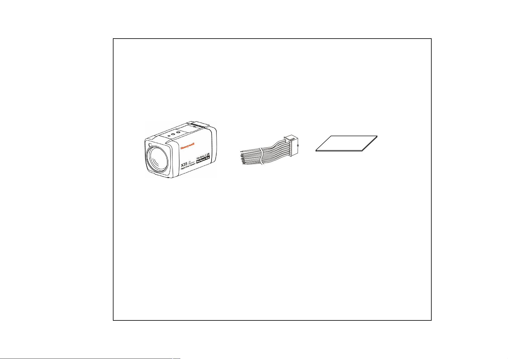
3.1 Check all accessories with enclosed package .
-HZC-855NX/PX Ser. SET
-14 PIN CONNECTION CABLE (150mm)
-OPERATION MANUAL
HZC-855NX/PX Ser. 14 PIN CABLE*
* CABLE DESCRIPTION
1. KEY1
3. ZOOM
5. MENU
7. GND
9. R+/NC
11. T+/TD
13. EXT_VD
( RED )
( GREEN )
( WHITE )
( BLACK )
( BROWN )
( VIOLET )
( WHITE )
2. KEY2
4. FOCUS
6. COM
8. GND
10. R-/RD
12. T-/GND
14. GND
-7-
OPERATION MANUAL
( YELLOW )
( BLUE )
( ORANGE )
( BLACK )
( PINK )
( GRAY )
( BLACK)
Page 8

4. Camera Control Methods
4.1 Remote Control using for Hard wired connection ( Connector pin 3,4,5,6 )
14P CableController
TELE (-)
WIDE(+)
14P Cable
NEAR(+)
FAR (-)
MENU ON
4.2 Remote Control using for RS-232C connection ( Connector pin 10,11,12 )
Connect to Serial PORT
Serial Cable
( 9 Pin D-Sub )
2
RD
3
TD
5
SG
( COM1 or COM2 )
14P Cable
RD(TxD)
10
11
TD(RxD)
12
GND
Serial Cable
14P Cable
Relay
Relay
Relay
3
4
5
6
ZOOM
FOCUS
MENU
COM
-8-
Page 9

4.3. Remote Control using for RS-422/485 connection ( Connector pin 9,10,11,12 ) --------OPTION
Connect to Serial PORT
(COM1 or COM2)
Serial Cable
( 9 Pin D-Sub )
2
RD
3
TD
5
SG
Serial Cable
14P Cable
RD(TxD)
10
11
TD(RxD)
12
GND
485 Converter
14P Cable
422
RS-485 Converter
T+
T-
R+
R-
485
RS-485 Converter
TRxD+
TRxD-
14P Cable
R +
9
10
R-
11
T+
12
T-
14P Cable
R +
9
10
R-
11
T+
12
T-
-9-
Page 10

5. On Screen Display
⑧ ⑧
① ②
⑦
③,④
⑤
⑧
⑥
Focus Mode
①
②
③
Shutter Speed
④
⑤
FUNCTION
Back Light
Flickerless
Night Mode
OSD Format
Non display
MF
Non display
BL
Non display
FL
Non display
1 / 125
.
.
1 / 5 0, 0 0 0
Non display
DESCRIPTION
Auto Mode
Manual / OneshotMode
Backlight OFF
Backlight ON
FlickerlessOFF
FlickerlessON
NTSC:1/60
9 variable steps
NightshotOFF
NightshotONIR
<Fig5-1. Operating OSD display position>
5.1 How to display Operating OSD
a. Pressing the MENU key softly confirm current Operating OSD.
It is disappeared about five seconds later if there are no other key actions.
b. When it zoom in or out pressing TELE(up) or WIDE(down) key,
whole Operating OSD is displayed and then disappeared.
Press NEAR(+) , FAR(-) key, only upper part of Operating OSD
( for displaying camera mode ) is displayed and then disappeared.
(It is for checking current whole camera mode and zoom position )
c. Even though Operating OSD is disappeared,
it keep displaying ID in lower part of screen.
In order to do not display ID, one method is to change EEPROM data
of Camera, the other is to use external communication through RS-232C.
d. Using RS-232C communication, change display position of ID;
Bottom Right -> Top Left -> Top Right -> Non display.
* If display Operating OSD is not needed by special purpose
like using external text overlay board, it can be OFF modeat all times
through external communication control as RS 232C.
⑥
WB MODE
ZOOM
DISPLAY
⑦
CAMERA
⑧
ID/TITLE
-10-
Non display
IN
OUT
MWB
AWB Auto WB mode
x35
Dx90
>> TELE
<< WIDE
Non display
ID : 002
TITLE DISPLAY set as TITLE
Auto Tracking WB mode
Indoor Preset (3200°K)
Outdoor Preset (5400°K)
Manual WB mode
One Push modeAWC
Optical Zoom
Digital Zoom
zoom IN
zoom OUT
In case that ID is 0
In case that ID is 1 ~ 255
<Table5-1. Operating OSD description>
Page 11

5.2 OSD SETUP MENU Structure
SETUP
MENU
LENS MODE
AE MODE
WB MODE
NIGHTSHOT
MODE
BLC/WDR
MODE
PZM
SETTING
CAMERA ID
SETTING
ZOOM SPEED
START ZOOM
END ZOOM
E-ZOOM
AF MODE
O. RESET
O. AF TIME
AF SENS.
MIN. DIST.
MODE
CONTROL
RED GAIN
BLUE GAIN
MODE
LEVEL
CAMERA ID
DISPLAY
POSITION
1 ~ 10
x1 ~ x34
X35 ~ x90
ON/OFF
ONESHOT/MANUAL..
ON/OFF
1 ~ 10
HIGH/ LOW/AF SENS
1cm ~ INF.
ATW/AWC/MWB/…
AUTO/LOCK/…
0 ~ 255
0 ~ 255
BLC/H.BLC/WDR/…
0 ~ 15
0 ~ 255
CAM ID/TITLE
R.BOT/L.TOP/L.BOT…
MODE
LOW SHUTTER
HIGH SHUTTER
IRIS
GAIN
BRIGHTNESS
MAX GAIN
MAX FIELDS
MODE
DETECT TIME
DETECT MODE
D->N LEVEL
N->D LEVEL
NIGHT COLOR
ZONE NUM.
CONTROL
H START
H END
V START
V END
PZM MASKING
AUTO/SHT FIX/IRIS...
2FLDS ~ 510 FIELDS
1/60 ~ 1/50000
CLOSE ~ F1.6
8 dB ~ 38 dB
0 ~ 99
8 dB ~ 38 dB
OFF ~ 510 FIELDS
OFF/AUTO/ON
1sec ~ 10 sec
BRT/CDS/BRT+CDS
0.1 lx ~ 100 lx
10 lx ~ 1000 lx
COLOR/ BW
1 ~ 8
ON/OFF
6 ~ 658
106 ~ 758
6 ~ 407
86 ~ 487
BLUE/RED/CYAN/…
SPECIAL
FUNCTION
FACTORY
DEFAULT
MIRROR
SHARPNESS
NEGATIVE
COLOR
FREEZE
BAUDRATE
PROTOCOL
F.OSD DISP.
OFF/H MIRROR/…
0 ~ 15
ON/OFF
ON/OFF
ON/OFF
4800bps ~ 512kbps
DEFAULT/VCL/KD6..
ALL/NONE/TOP/…
-11-
Page 12

5.2 Display SETUP MENU
a. Press MENU key above 2 seconds so that SETUP MENU 1 is
displayed on the screen.
b. Select item of SETUP MENU using TELE(up) / WIDE(down) key.
c. NEAR(+) / FAR(-) key is used to increase / decrease data of
selected item.
<< SETUP MENU >>
LENS MODE
AE MODE
WB MODE
NIGHTSHOT MODE
BLC/WDR MODE
PZM SETTING
CAMERA ID SETTING
SPECIAL FUNCTION
FACTORY DEFAULT
<< LENS MODE >>
ZOOM SPEED 10
START ZOOM x1
END ZOOM x90
E-ZOOM ON
AF MODE ONESHOT
O.RESET OFF
O.AF TIME 5 sec.
AF SENS. HIGH
MIN. DIST. 50cm
RETURN
Setup menu1
Setup menu2
<Fig5-2. SETUP MENU change>
5.3 Move between SETUP MENU 1 and SETUP MENU 2
a. In order to change from SETUP MENU1 to SETUP MENU 2,
select NEXT MENU using TELE / WIDE key, and press
NEAR / FAR key.
b. In order to change from SETUP MENU 2 to SETUP MENU1 ,
select RETURN MENU using TELE / WIDE key, and press
NEAR / FAR key.
5.4 Quit SETUP MENU
a. Press the MENU key again. SETUP MENU is disappeared,
“SAVE?” or “QUIT?” is displayed at center of screen.
If there is no change of adjustment state of Camera,
“QUIT?” is showed, else “ SAVE?” is showed.
① “QUIT?” : quit SETUP MENU without saving changed value.
② “SAVE?” : quit SETUP MENU with saving changed value.
b. Press NEAR / FAR key to choose, and press the MENU key again.
whole SETUP MENU is quitted.
( If MENU key is not pressed and TELE / WIDE key is pressed,
SETUP MENU is appeared again. )
<< LENS MODE >>
ZOOM SPEED 10
START ZOOM x1
END ZOOM x35
E-ZOOM OFF
AF MODE ONESHOT
O.RESET OFF
O.AF TIME 5 sec.
AF SENS. HIGH
MIN. DIST. 50cm
RETURN
5.5 LENS MODE
① ZOOM Speed Control
: Set zoom speed 1 to 10, 10 steps.
ZOOM SPEED 1 → 2 → … → 10
② Start Zoom Ratio
: Set boundary value of WIDE zooming.
START ZOOM x 1 ~ x 34 ( in optical zoom region )
③ End Zoom ratio
: Set boundary value of TELE zooming. It can be set up to x90
including electronic zoom. ( in case the digital zoom limit is 2.5
times ) Since Start Zoom and End Zoom ratio are set,
simultaneously Camera moves to setting zoom times. So it can be
enable to adjust in moving to desired position.
END ZOOM x 35 ~ x 90 ( in digital zoom region )
-12-
Page 13

④ E-Zoom Control
: ON means up to x230, OFF means only optical zoom region.
E-ZOOM OFF → ON → . . . .
⑤ Set Focus Mode
: It is composed of three modes.
AUTO
:Use to focus automatically all the time.
MANUAL
: Use to focus manually by pushing NEAR(+) / FAR(-)key.
Even though MANUAL mode, it will be focused in about 5 seconds
after zoom in(TELE) / out(WIDE), and return to MANUAL mode
automatically.
This is for focusing accurately after zooming.
ONESHOT
: It is similar to MANUAL mode. But there are some difference.
In case the focus mode is ONESHOT, it is focused whenever
ONESHOT (AUTO/MANUAL key) key is pushed. It will be returned
to MANUAL mode
after seconds (Special Menu : O.S. AF TIME) even though can not
be found best focus. In this case push ONESHOT(AUTO/MANUAL
key) key again, it will be in best focus.
PUSHAUTO (option)
: While pushing key, Focus mode will be AUTO.
☞ caution
1. According to Model , order is Auto -> Manual -> Oneshot, or Auto >
Manual -> Pushauto.
<< LENS MODE >>
ZOOM SPEED 10
START ZOOM x1
END ZOOM x90
E-ZOOM ON
AF MODE MANUAL
O.RESET OFF
O.AF TIME 5 sec.
AF SENS. HIGH
MIN. DIST. 50cm
RETURN
⑥ONESHOT AF RESET
: Use in case of focus deviation due to impact, vibration etc.
Auto Focusing is operated during set time.
O.RESET OFF → ON → ….
☞ caution
1. It happens focus deviation according to circumstance condition
( brightness, facility to focus the object, etc ).
⑦ ONESHOT AF TIME
: Set OneshotAF operating time. When AF is completed, Focus mode
will be Manual. Though AF is not completed, it stops when time is
up.(unit:sec)
O.AF TIME 1 → 2 → … → 10
⑧ AF Sensitivity
: HIGH : Reaction of Auto Focus is fast. It can be used when it shoot
objects moving fast.
LOW : Auto Focus is more stable. In fast moving scene, AF doesn’t
work even though the scene is changed. It is for stabilizing
the scene.
AF SENS. HIGH → LOW → ….
⑨ Minimum Distance
: Set the minimum distance which can be focalized.
MIN. DIST. 1cm → 10cm → 50cm → 1m → 3m →
10m → INF.
<< LENS MODE >>
ZOOM SPEED 10
START ZOOM x1
END ZOOM x90
E-ZOOM ON
AF MODE MANUAL
O.RESET OFF
O.AF TIME 5 sec.
AF SENS. HIGH
MIN. DIST. 10cm
RETURN
<Fig5-4. Minimum Focus Distance MODE>
<Fig5-3. LENS MODE >
-13-
Page 14
<< SETUP MENU >>
LENS MODE
AE MODE
WB MODE
NIGHTSHOT MODE
BLC/WDR MODE
PZM SETTING
CAMERA ID SETTING
SPECIAL FUNCTION
FACTORY DEFAULT
<Fig5-5. AE MODE >
5.6 AE MODE
① Exposure Mode
: It is composed of five modes according to circumstantialilluminance.
AUTO
: Exposure is controlled by Shutter Speed,Iris,Gainto meet the
Brightenss.
SHUTTER FIX
: Low/High shutter speed is fixed, Exposure is controlled by Iris and
Gain.
IRIS FIX
: Iris is fixed, Exposure is controlled by Shutter Speed and Gain.
(Shutter Speed,GAINis not adjust and operate automatically.)
GAIN FIX
: Gain is fixed, Exposure is controlled by Shutter Speed and iris.
MANUAL
: Shutter Speed,Iris,Gainis fixed as set value regardless of
illuminance.
☞ caution
1. There are menu items not to adjust and to skip according to
mode.
2. Field Integration is not operated in Shutter Fix, Gain Fix, Manual.
MODE AUTO → SHT FIX → IRIS FIX →
GAIN FIX → MANUAL
② LOW SHUTTER Speed
: In Shutter Fix,ManualMode, range is from 1/30 sec (2 fields)
to 2 sec (128 fields).
LOW SHUTTER OFF → 2 FLDS ~ 128FLDS
(FLDS means how many times integrated of CCD signal.)
③ HIGH SHUTTER Speed
: In Shutter Fix,ManualMode, range is from 1/60 sec to
1/10,000 sec.
HIGH SHUTTER 1/60 → 1/100 → . . . . → 1/10000
④ IRIS
: In Iris Fix, Manual Mode, range is 17 phases from F1.6
(full Open) to CLOSE.
IRIS CLOSE → F22 → F19 → . . . . → F1.6
⑤ GAIN
: In Gain Fix, Manual Mode, range is 17 phases from 8 to 38dB.
GAIN OFF → 8dB → 10dB → . . . . → 38dB
⑥ Brightness
: Adjust level of Auto Iris. The smaller brightness value is, the darker
it is, because iris is closed more. On the contrary the bigger
brightness value is, the brighter it is, because iris isopened more.
BRIGHTNESS 0 ~ 99
⑦ MAX AGC
: Adjust Max AGC level.
MAX GAIN OFF→ 8dB → 10dB → . . . . → 38dB
☞caution
Max Gain is less than 14dB, and Field Integration does not work.
<< AE MODE >>
MODE IRIS FIX
LOW SHUTTER NOT USE
HIGH SHUTTER 1/60
IRIS F5.6
GAIN AUTO
BRIGHTNESS 40
MAX GAIN 34dB
MAX FIELDS 20FLDS
RETURN
<Fig5-6. Brightness in AE Mode >
-14-
Page 15

⑧MAX FIELDS (option)
: Use for compensating the low illumination condition. In case that use
this function because of low illumination condition, adjust maximum
integration fields to get brighter and dynamical image. But the scene
becomes slower than OFF mode. The larger max fields is,
simultaneously the noise of image is larger. This is phenomenon
because too small video output is integrated on many fields memory.
To get more dynamical image, adjust maximum integration fields
and set maximum AGC gain as HIGH, then make better the
standard of dynamic image.
5.7 White Balance Mode
① White Balance Mode
: Outer illumination condition is expressed by Color temperature,
Kelvin (°K). It is White Balance that shows white as white in any
illumination conditions. It is composed of five modes..
ATW ( Auto Trace White balance )
: Traceautomatically under any condition in range 2,800°K~ 8,000°K
( It can be adjustable red and blue point of desired white position. )
MAX FLDS OFF → 2FLDS → 3FLDS → 4FLDS → 5FLDS
→ 6FLDS → 7FLDS → 8FLDS → …. →
→ 80FLDS → 160FLDS→ 320FLDS
→ 510FLDS
☞caution
1. In Fields Integration mode, noises as well as video information are
increased. When an ambient temperature keeps high, CCD pixel
defect happens to be larger and white. This is not due to failure.
<< SETUP MENU >>
LENS MODE
AE MODE
WB MODE
NIGHTSHOT MODE
BLC/WDR MODE
PZM SETTING
CAMERA ID SETTING
SPECIAL FUNCTION
FACTORY DEFAULT
<< WB MODE >>
MODE ATW
CONTROL FRAME
RED GAIN NOT USE
BLUE GAIN NOT USE
RETURN
AWB
: Consider current illumination condition, do white balance by force
and lock as manual
INDOOR
: Use to set the preset illumination condition as 3200°K
OUTDOOR
: Use to set the preset illumination condition as 5400°K
MANUAL
: Use to adjust to desired RED, BLUE gain manually.
AWC
: Consider current illumination condition, do white balance by
force and lock as manual
② White Balance Mode Control
: It displays and changes White Balance Mode Control status of
Camera. ( According to Mode, it just display the state and not to
adjust.)
ATW AUTO
INDOOR 3200°K
OUTDOOR 5400°K
MANUAL R/B CONT
AWC LOCK → PUSH → . . . .
AWB AUTO
(LOCK means Manual white balance status. Press NEAR(+) /
FAR(-) key continuously, LOCK mode becomes PUSH mode and
white balance acts automatically, and then white balancemode is
locked as manual.)
<Fig5-7. WB MODE >
-15-
Page 16

③RED GAIN (Range is different on each Mode.)
: Adjust RED Gain, and tune the sensitivity of white point.
MANUAL 0 → 1 → …. → 254 → 255
④ BLUE GAIN (Range is different on each Mode.)
: Adjust BLUE Gain, and tune the sensitivity of white point.
MANUAL 0 → 1 → …. → 254 → 255
<< SETUP MENU >>
LENS MODE
AE MODE
WB MODE
NIGHTSHOT MODE
BLC/WDR MODE
PZM SETTING
CAMERA ID SETTING
SPECIAL FUNCTION
FACTORY DEFAULT
5.8 NIGHTSHOT MODE
① NIGHTSHOT MODE
: It is used in low illumination condition. ON is Night mode, OFF is
normal state. Sensitivity of camera becomes more higher level like
BW camera.
It can be available external IR illuminator. In case ofAUTO mode is
converted ON / OFF automatically according to illuminancechange.
MODE OFF → AUTO → ON → ….
② NIGHTSHOT MODE DETECT TIME
: Set time to protect susceptible conversion of ON/OFF according to
illuminancechange on Auto. When illuminacekeeps the state during
detect time, convert ON/OFF.
DETECT TIME 1 sec. → 2 sec. → …. → 10 sec.
③ NIGHTSHOT DETECT MODE
: It is good to use with external IR illuminator on Auto. Select CDS
sensor ON/OFF to detect the illuminancestate more effectively.
DETECT MODE BRT → CDS → BRT+CDS → ….
☞ caution
BRT means shooting scene brightness, CDS sensor’s operation
depends on circumstantial brightness. Select to match with installation
circumstance.
④ Turnover LEVEL from DAY TO NIGHT
: Set the LEVEL to turnover from Day to Night.
D→N LEVEL 0.1 lx → 1 lx → 10 lx → ….
⑤ Turnover LEVEL from NIGHT TO DAY
: Set the LEVEL to turnover from Night to Day.
N→D LEVEL 10 lx → 100 lx → 1000 lx → ….
⑥ Color on NightshotMode
: Set Color Mode on Night Mode.
NIGHT COLOR B/W → COLOR → ….
<< NIGHTSHOT MODE >>
MODE AUTO
DETECT TIME 5sec
DETECT MODE BRT
D->N LEVEL 1lx
N->D LEVEL 100lx
NIGHT COLOR B/W
RETURN
<Fig5-8. NIGHTSHOT MODE >
<< SETUP MENU >>
LENS MODE
AE MODE
WB MODE
NIGHTSHOT MODE
BLC/WDR MODE
PZM SETTING
CAMERA ID SETTING
SPECIAL FUNCTION
FACTORY DEFAULT
<Fig5-9. BLC/BMB Mode >
-16-
Page 17

5.9 BLC/ WDR Mode
① Backlight Compensation Mode
: It is for preventing the center object too darken when the excessive
light is behind the center object. Set BACKLIGHT ON, then brighten
the center object in the contrast to the background light. Press
NEAR/ FAR key in 2 sec, Backlight mode become AUTO.
MODE OFF → BLC → H.BLC → WDR → ….
H.BLC [Histogram BLC] is enhanced BLC function.
H. BLC makes the center object brighter to clear image
where the behind scene is too brighter than the center object.
② Backlight Compensation Level
BLC LEVEL 7 ( 0 ~ 15 )
③ Histogram BLC Level (H.BLC LEVEL)
H.BLC LEVEL 10 ( 0 ~ 15 )
<< BLC/WDR MODE >>
MODE WDR
WDR LEVEL 5
RETURN
WDR [Wide Dynamic Range]
WDR is mostly useful function to take image from indoor to
window. WDR is the new technology to reduce the
differentiations between dark and bright areas.
④ WDR Level
WDR LEVEL 5 ( 0 ~ 15 )
☞Cautions
1. While using WDR mode toward fluorescent lamp or bright
light, you may find out unwanted color. However, thisis
normal condition for WDR function.
2. While using WDR mode, the digital zoom does not work.
<< SETUP MENU >>
LENS MODE
AE MODE
WB MODE
NIGHTSHOT MODE
BLC/WDR MODE
PZM SETTING
CAMERA ID SETTING
SPECIAL FUNCTION
FACTORY DEFAULT
<Fig 5-10. Privacy Zone Setting >
5.10 PRIVACY ZONE
① Set Privacy ZONE
:PZM(PrivacyZone Mask) is to hide the unwanted view to protect
privacy invasion. It works with Zoom/PAN/TILT operation. Select
PZM zone upto8 zones.
ZONE NUM. ZONE 1 → ZONE 2 → …. → ZONE 8
② PZM control
: Set ON/OFF for each PZM Zone.
CONTROL OFF → ON → ….
③ PZM Horizontal center starting point
: Set PZM for the starting point of Horizontal center.
H START 332
④ PZM Horizontal center ending point
: Set PZM for the ending point of Horizontal center.
H END 432
⑤ PZM Vertical center starting point
: Set PZM for the starting point of vertical center.
V START 206
⑥ PZM Vertical center ending point
: Set PZM for the ending point of vertical center.
V END 286
⑦ PZM Masking
: Choose the Color to mask the PZM zone. 8 color
(Black,Gray, Light Gray,White,Red,Blue,Green,Yellow) is
available.
PZM MASKING BLUE →RED → …. → GREEN
-17-
Page 18

Quick setting method for Privacy Zone Masking
1. Zoom in wide as possible as you can.
2. Select Zone Number in “ZONE NUM.”.
3. Select “On” by push the right button.
4. Push Menu button on the “CONTROL” to be able to move to
wanted position spot and push again to go back to main Menu.
5. Set the H and V value on the Menu.
6. Select a color.
7. Push Menu button to save the setting.
<< PRIVACY ZONE >>
ZONE NUM. ZONE1
CONTROL ON
H START 332
H END 432
V START 206
V END 286
PZM MASKING BLUE
RETURN
PRESS MENU TO MOVE
5.11 Camera ID SET
① ID SET
: Camera ID is indicating number assigned each Camera in case of
controlling many Cameras. It is from 0 to 255. But in case of 0,
that is not displayed on screen. It is always displayedeven though
whole Operating OSD is disappeared on the screen. But it is
possible to make non display and to choose display position
(BOTTOM RIGHT, TOP RIGHT, TOP LEFT) by RS-232C
communication.
CAMERA ID 0 ~ 255
☞ caution
1. In case of Camera ID FIX model, it cannot be selected..
2. ID is not changed by MENU control through communication.
② DISPLAY MODE
: Choose which is to display Camera ID or Title.
DISPLAY CAM ID → TITLE → ….
③ DISPLAY POSITION
: Choose where is to display Camera ID or Title on Right Bottom,
Left Top, Right Top or not to display.
POSITION R.BOT → L.TOP → R.TOP → NONE
TELE: ↑, WIDE: ↓
NEAR: →, FAR: ←
RETURN MENU
<Fig 5-11. Privacy Zone Setting >
<< SETUP MENU >>
LENS MODE
AE MODE
WB MODE
NIGHTSHOT MODE
BLC/WDR MODE
PZM SETTING
CAMERA ID SETTING
SPECIAL FUNCTION
FACTORY DEFAULT
-18-
<< CAMERA ID SET >>
CAMERA ID 001
DISPLAY CAM ID
POSITION R.BOT
ABCDEFGHIJKLMNOPQRST
UVWXYZabcdefghijklmn
opqrstuvwxyz12345678
9!?#$%&<>*,.:;/+-=~ ■
TITLE : HONEYWELL
RETURN
<Fig 5-12. CAMERA ID Setting>
Page 19

④ Title
: It is the name of Camera. It enters 10 characters including blank..
TITLE: ■■■■■■■■■■
▣ How to Enter the Title ▣
Let’s enter the Title as “R1” , example
-. Select the position of title character by using Near or Far key.
The chosen position is blinking.
(Only chosen Cursor will be blink as “■”, rest of them
will be shown as a blank “”.)
TITLE: □
-. Select the character “R” among ⓐ ~ ⓓ by using UP,DOWN,
(+),(-) key. The chosen character “R” is blinking.
ABCDEFGHIJKLMNOPQRST
UVWXYZabcdefghijklmn
opqrstuvwxyz12345678
9!?#$%&<>*,.:;/+-=~■
-. Press MENU key, the character “R” is entered in the Title.
(Automatically the position will be forward to next position.)
TITLE: R □
-. If you want to edit specified character, you shall use
TELE/Wide to move on the position and NEAR/FAR to
select on the character. By using TELE/WIDE to position
the character to continue to edit.
-. Select character “1” using TELE, WIDE, NEAR, FAR
button and it will blink the cursor on the character “1”
ABCDEFGHIJKLMNOPQRST
UVWXYZabcdefghijklmn
opqrstuvwxyz12345678
9!?#$%&<>*,.:;/+-=~■
-. Push MENU to enter the character “1”.
TITLE: R 1 □
<< SETUP MENU >>
LENS MODE
AE MODE
WB MODE
NIGHTSHOT MODE
BLC/WDR MODE
PZM SETTING
CAMERA ID SETTING
SPECIAL FUNCTION
FACTORY DEFAULT
5.12 SPECIAL FUNCTION
① Mirror Mode
: Mode ON is Mirror Mode, OFF is general screen state.
MIRROR OFF → H MIRROR →
② Sharpness
: Use to change the contour of Scene.
SHARPNESS 0 ~ 15
③ Negative Mode
: Use for Positive and Negative mode. ON is Negative mode, OFF is
Positive mode namely general screen state.
NEGATIVE OFF → ON → ….
④ Color Mode
: Use for changing color and monochrome ( black & white )mode .
ON is Color mode, OFF is black&whitemode.
COLOR ON → OFF → ….
<< SPECIAL FUNCTION >>
MIRROR OFF
SHARPNESS 8
NEGATIVE OFF
COLOR ON
FREEZE OFF
BAUDRATE 9600bps
PROTOCOL DEFAULT
F. OSD DISP ALL
RETURN
V MIRROR → FLIP . . . .
<Fig 5-13. SPECIAL FUNCTION>
-19-
Page 20

⑤Freeze Mode
: It pause current image. ON is to stop, OFF is to return to normal
state.
FREEZE ON → OFF → ….
☞ caution
1. Freeze image does not save when you reset the system.
This system doesn’t have its’ own memory.
⑥ BAUD RATE
: Use to communicate through RS232C, RS485, RS232TTL .
BAUDRATE 4800bps → 9600bps → ….
☞ caution
1. If the Baud Rate does not match between Camera and external
system, it may occur the communication failure. Please make
sure a proper Baud Rate.
⑦ PROTOCOL Setting
: Setting the PROTOCOL with communication device.
PROTOCOL DEFAULT → VCL → KD6 → P/D → ….
⑧ Function OSD Display
OSD DISP ALL → NONE → TOP →
ALL : Whole Function OSD display
TOP : Only Upper OSD display ( Focus Mode, key
BOTTOM : Only Lower OSD display ( Zoom Ratio, ID )
NONE : All the OSD will not display except MENU
☞
Caution
1. The display of ID and TITLE can be only set in CAMERA ID
SETTING.
→ 312kbps
BOTTOM → ....
( Focus Mode, Key state, Zoom Ratio, ID )
state )
OSD.
5.13 Initial Set
: Set the INITIAL SET Mode ON so that all changed data are
returned to shipping condition. For Initialization, select “YES?” by
using NEAR, FAR key and push MENU key. Select “NO?”
and push MENU, no initialization and return to Main Menu.
☞ caution
1. Make sure when Initialization set as “YES?” , all changed data are
return to shipping condition.
2. Some menu as ID,TITLE, etc are not initialized.
-20-
Page 21

6. Specification
Pick up Device
Total/Effective Pixels
Scanning System
Lens
Digital Zoom Ratio
Sync. System
H. Resolution
S/N Ratio
Min. illuminance
Focus Mode
Brightness
Shutter Speed
Field Integration
Mirror
Day & Night Mode
Privacy Zone
AGC
White Balance
BLC ( BMB )
Remote Control
Power Supply/Consump.
Operation/Storage Temp.
Dimension / Weight
HZC-855NXModel Name
1/4” Sony Double Scan CCD ( Ex-View CCD )
410,000 / 380,000
2:1 Interlace
Optical x35, f = 3.6~126mm, F1.65(WIDE) ~ F4.2(TELE)
x36 ~ x90 can be adjustable
Internal line lock/ VD pulse lock( AutoDetect)
More than 530 TV Lines
More than 50 dB ( AGC OFF )
0.5 lx (30IRE) ; 0.05 lx (IR FILTER OFF) ;
0.0005 lx (510 fields) ; 0.00001 lx (510 fields, IR FILTER
RS-232C
OFF)
Auto / Manual / Oneshot
0 ~ 99 adjustable
1/60(50) ~ 1/50,000
x2 ~ x510 adjustable
Horizontal Mirror / Vertical Mirror / FLIP(HorizontalMirror + Vertical Mirror )
AUTO / ON / OFF ( CDS Sensor ON/OFF)
ON ( Max 8 area ) / OFF
ON ( 8 ~ 38dB ) / OFF
AUTO(ATW, AWC) / OneShot/ Indoor / Outdoor / Manual /AWB
BLC : ON / OFF / H.BLC ,/ WDR
DC 9V ~ DC 14V ( Motor Activate6 W , Motor Stop 4.0 W )
-10 ~ 60 ℃( Recommended -5 ~ 50 ℃) / -20 ~ 60 ℃
62 x 71.6 x 116 (mm) / 510g
HZC-855PX
470,000/440,000
More than 49 dB ( AGC OFF )
0.6 lx (30IRE) ; 0.06 lx (IR FILTER OFF) ;
0.0006 lx (510 fields) ; 0.00001 lx (510 fields, IR
FILTER OFF)
RS-232C
HZC-855PX-VRHZC-855NX-VR
RS-422 / RS-485RS-422 / RS-485
-21-
Page 22

7. Dimensions
VIDEO
SVIDEO
-22-
Page 23

MEMO
Honeywell Co., Ltd.
Address : 17F, KukjeCenter Building 191, Hankangro-2ga,
Yongsan-gu, Seoul 140-702, Korea
Phone : 82-2-799-6109, 6108, 6107, 6292
Fax : 82-2-749-6119
http : //www.honeywell.co.kr/security/english
E-mail : info.security@honeywell.com
Printed in Korea
G-113864-001
-23-
 Loading...