

Page 1
HX 85
Erweiterungsmodul
Montage und Bedienung
Expansion Module
Mounting and Operation
Módulo de extensión
Montaje y funcionamiento
Page 2

Page 3

Inhalt
Inhalt
Anwendung 3
Betriebsarten 4
Kommunikation zum HCM 200D 8
Vorgehen bei der Installation 11
Montage 12
Klemmenbelegung 14
Betriebsart einstellen 16
Geräte/Sensor an HX 85 anschließen 16
Teach-in 21
Teach-in am Hometronic Manager aktivieren 21
Teach-in am Erweiterungsmodul HX 85 durchführen 23
Fühler deinstallieren 25
Lifestyles zuordnen 28
Digitale Eingänge/X-10 Kommandos prüfen 31
Status der digitalen Eingänge senden 32
Glossar 33
Technische Daten 34
Hilfe im Problemfall 35
1
Page 4

Page 5
Anwendung
Lesehinweis
Fachbegriffe sind im Glossar (Seite 33) erläutert.
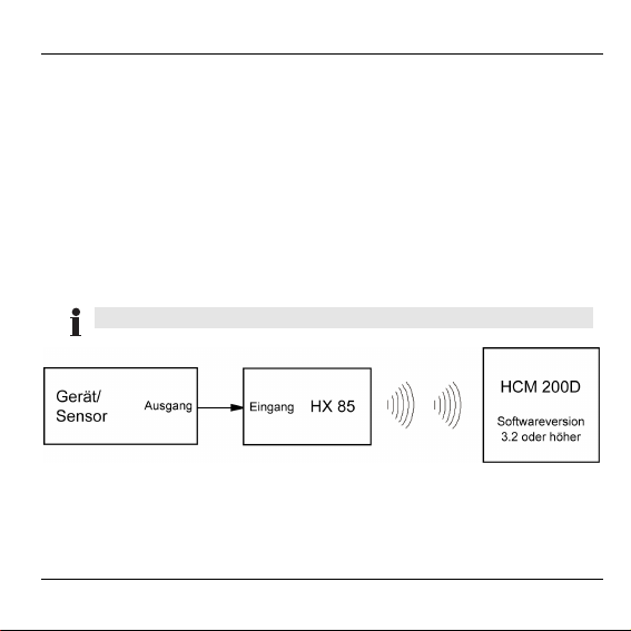
Anwendung
Das Modul HX 85 hat zwei verschiedene Betriebsarten, die je nach
Anwendung entweder als Fühler oder Alarmanlage Lynx einstellbar
sind. Insgesamt stehen 5 digitale Eingänge zur Verfügung. Die
Betriebsart 1 erlaubt die Verarbeitung von 5 digitalen Eingängen, die
Betriebsart 2 die Kommunikation mit ADEMCO-Alarmanlagen (Lynx)
über die X-10 Schnittstelle. Die jeweilige Betriebsart wird über DIPSchalter eingestellt.
Betriebsart 2 ist nur mit HCM 200D möglich.
Der Status eines digitalen Eingangs wird im HCM 200D über JA-NEIN
angezeigt. Jedem Zustandswechsel eines digitalen Eingangs lässt
sich am Hometronic Manager HCM 200D ein entsprechender Lifestyle
zuordnen.
3
Page 6
Betriebsarten
Betriebsarten
Aus Sicht des HCM 200D verhalten sich die Betriebsart 1 für die
Verarbeitung von 5 digitalen Eingängen und die Betriebsart 2 für die
Integration der ADEMCO-Alarmanlage gleich. Die digitalen Eingänge
1–5 entsprechen den Geräteadressen A1–A5 des X-10 Protokolls,
d. h. der erste Fühlereingang entspricht A1, der zweite Fühlereingang
entspricht A2 usw.
Es kann nur eine der beiden Betriebsarten B1 oder B2
gewählt werden. Die Betriebsart B2 ist nur mit HCM 200D
möglich.
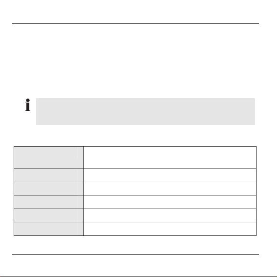
Adressenzuordnung
BA 1 (DI) BA 2 (X-10), nur in Verbindung mit
1 Hauscode: A / Keycode: 1
2 Hauscode: A / Keycode: 2
3 Hauscode: A / Keycode: 3
4 Hauscode: A / Keycode: 4
5 Hauscode: A / Keycode: 5
4
HCM 200D möglich
Page 7
Betriebsarten
Für die BA 2 muss bei der Programmierung der Alarmanlage
sichergestellt sein, dass der Hauscode A für die Auslösung
des Alarms verwendet wird.
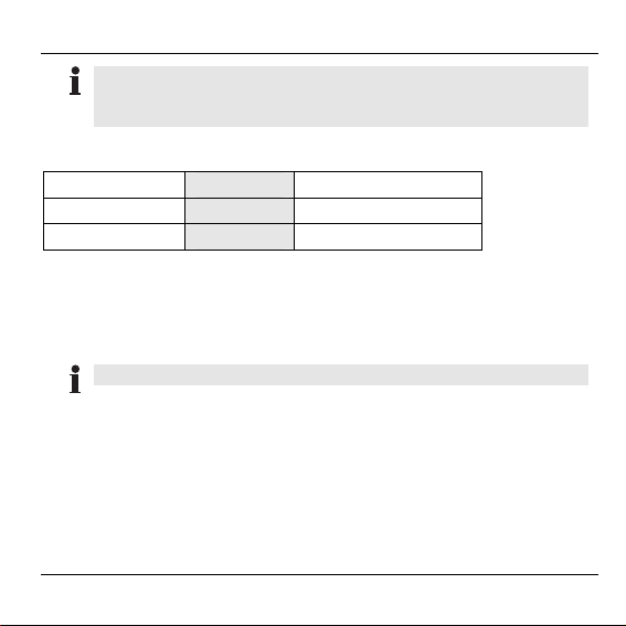
Zuordnungstabelle zwischen Eingangsspannung und Betriebsart
Spannung DI BA1 (DI) BA2 (X-10)
0V Low (0) OFF
12 VAC / VDC High (1) ON
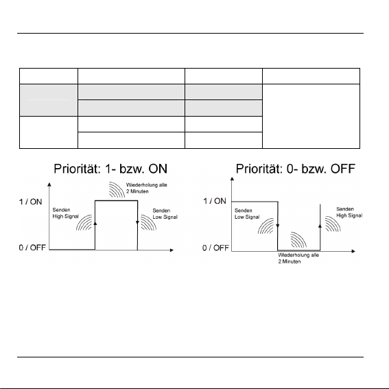
Betriebsart und Priorität* einstellen
Die Einstellung der Betriebsart umfasst die Festlegung auf die
Betriebsart 1 oder 2 und die generelle Einstellung der Priorität für den
digitalen Eingang DI1 bzw. die Geräteadresse A1.
Die Priorität kann nur für DI1 bzw. A1 festgelegt werden.
Durch Vergabe der Priorität lassen sich sowohl in der BA 1 als auch in
der BA 2 Alarme vorzugsweise behandeln.
Ist der DI1 bzw. die Geräteadresse A1 auf Priorität gesetzt, wird der
Status des DI1 solange zyklisch (2 min ± 30 s) übertragen, bis die
Ursache des Alarms abgestellt wird. Am HCM 200D wird der durch
den Alarm ausgelöste Lifestyle ständig neu aktiviert.
5
Page 8
Betriebsarten
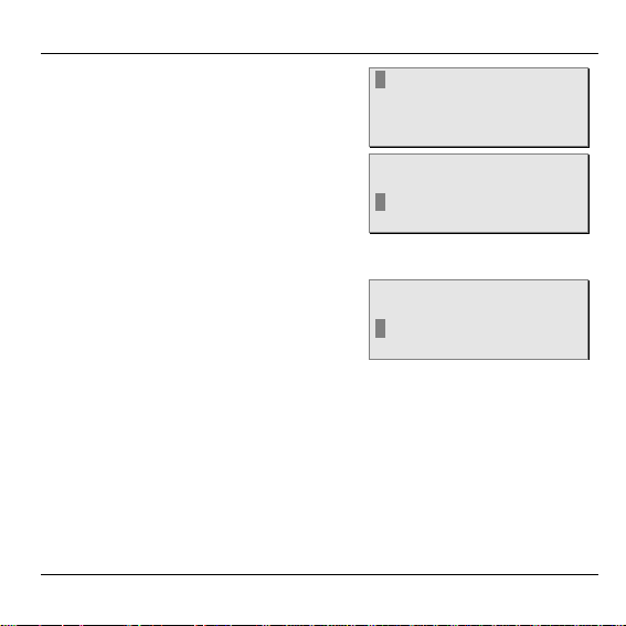
In Abhängigkeit des Eingangssignals und der Priorität wird das Signal
zyklisch gesendet.
DI Einganssignal Priorität
0 0 BA1
1 1
ON ON BA2
Signal wird
zyklisch
gesendet
OFF OFF
Ist der DI1 nicht auf Priorität gesetzt, wird der Status eines Eingangs
standardmäßig nach jedem Statuswechsel* gesendet.
6
Page 9
Betriebsarten
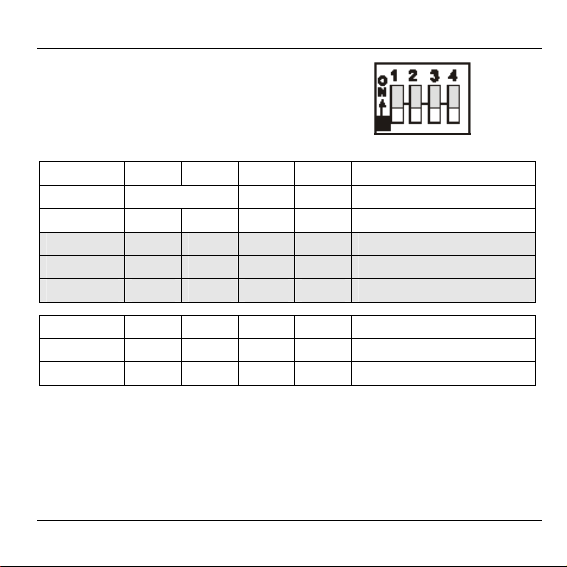
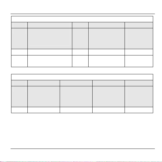
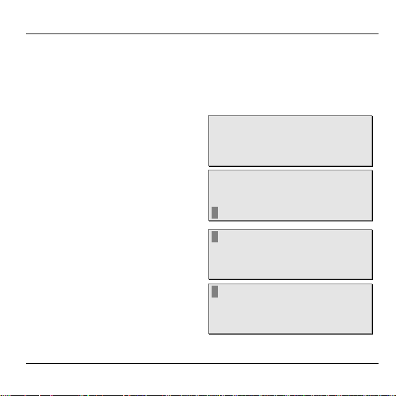
Priorität und Betriebsart werden über
4 DIP-Schalter wie folgt eingestellt:
Nr. 1 2 3 4 Bemerkung
Funktion Priorität BA -
BA 1 OFF OFF OFF OFF Keine Priorität gesetzt1
ON OFF OFF OFF Priorität 0
OFF ON OFF OFF Priorität 1
BA 2 OFF OFF ON OFF Keine Priorität gesetzt
ON OFF ON OFF Priorität OFF
OFF ON ON OFF Priorität ON
1
Alle anderen DIP-Schalterkombinationen verhalten sich wie OFF.
7
Page 10
Betriebsarten
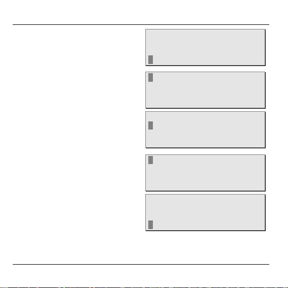
Kommunikation zum HCM 200D
Das HX 85 Erweiterungsmodul sendet ohne Zeitverzögerung, sobald
sich ein Eingangszustand ändert.
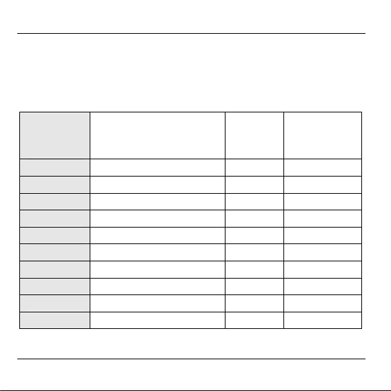
Die folgende Tabelle zeigt den Zusammenhang zwischen der
Statusanzeige des HCM 200D und den Eingängen.
BA 1
Digitale
Eingänge
DI 1: 1 -> 0 A1 = ON -> OFF NEIN
DI 1: 0 -> 1 A1 = OFF-> ON JA
DI 2: 1 -> 0 A2 = ON -> OFF NEIN
DI 2: 0 -> 1 A2 = OFF-> ON JA
DI 3: 1 -> 0 A3 = ON -> OFF NEIN
DI 3: 0 -> 1 A3 = OFF-> ON JA
DI 4: 1 -> 0 A4 = ON -> OFF NEIN
DI 4: 0 -> 1 A4 = OFF-> ON JA
DI 5: 1 -> 0 A5 = ON -> OFF NEIN
DI 5: 0 -> 1 A5 = OFF-> ON JA
8
BA 2
X-10 Schnittstelle
Geräteadresse + Daten
HCM200
Statusanzeige
Flanke zur
Lifestyleaktivierung
↓
↑
↓
↑
↓
↑
↓
↑
↓
↑
Page 11

Betriebsarten
Teach-in (Installation)
Die digitalen Eingänge werden im HCM 200D als Fühler installiert.
Jedes Erweiterungsmodul belegt bei der Installation immer 5
Fühlerplätze.
Beispiel:
Installation von 1 HX 85 Modul mit 1 x 5 Fühlern bei bereits 3
installierten Fühlern (Plätze 1–3).
Fühlerplatz Installation Deinstallation Installierte Fühler
Aussen-Temp ...
Hell ....
Wind .....
Fühler-4 HX 85 (1) Fühler-4
Fühler-5 Fühler-5
Fühler-6 5 Fühler Fühler-6
Fühler-7 Fühler-7
Fühler-8 Fühler-8
Nach der Installation eines Erweiterungsmoduls zeigt der HCM 200D
nur in der Betriebsart 1 unmittelbar die aktuellen Zustände an den
digitalen Eingängen an. In der Betriebsart 2 werden bei der
Inbetriebnahme sowie bei einem erneuten Teach-in alle Eingänge auf
"--" gesetzt, da noch keine X-10 Kommandos empfangen wurden.
9
Page 12

Betriebsarten
Die Fühlernamen sind editierbar und können in eine Frage
umgewandelt werden. Zum Beispiel:
Alarm: JA
Dachfenster zu? NEIN
Ventil geschlossen? JA
Lifestyles zuordnen (HCM 200D)
Jedem Statuswechsel lässt sich im HCM 200D ein entsprechender
Lifestyle zuordnen. Wird der Lifestyle 0 zugeordnet, ändert sich nichts
bei dessen Aktivierung. Wird der Lifestyle 17 zugeordnet, so wird bei
dessen Aktivierung in den Automatikbetrieb gewechselt.
Die Defaulteinstellung der Zuordnung Eingangszustand zu Lifestylenummer ist "0".
Ein zugeordneter Lifestyle wird im HCM 200D nur dann
angezeigt und ausgeführt, wenn für den Lifestyle mindestens
eine Aktion, z. B. "Gerät einschalten", programmiert wurde.
Lifestyles werden im Menü "Einstellungen/Erweiterungsmodule"
zugeordnet.
10
Page 13

Vorgehen bei der Installation
Vorgehen bei der Installation
Montage
• HX 85 montieren
• Geräte an HX 85 anschließen
• Betriebsart an DIP-Schaltern einstellen
Teach-in (Fühler installieren)
• Teach-in am HCM 200D (bzw. anderen Bediengeräten) aktivieren
• Teach-in am HX 85 durchführen
Lifestyles zuordnen (optional)
Am HCM 200D kann einem digitalen Eingang (X-10) bzw. einer
Geräteadresse ein Lifestyle zugeordnet werden, der bei einem
Statuswechsel ausgelöst wird.
Status der digitalen Eingänge senden
Per Tastendruck am HX 85 können die aktuellen Zustände der
digitalen Eingänge an den HCM 200D gesendet werden.
11
Page 14
Montage
Montage
Unzureichende Datenübertragung!
Warnung!
Störung des Funksenders im Gerät durch metallische
Gegenstände und weitere Funkgeräte.
► Achten Sie bei der Wahl des Betriebsorts auf
mindestens 1 m Abstand zu Funkgeräten wie FunkKopfhörern, schnurlosen Telefonen nach DECTStandard etc.
► Achten Sie auf ausreichende Distanz zu metallischen
Gegenständen.
► Wählen Sie bei nicht zu behebender Funkstörung
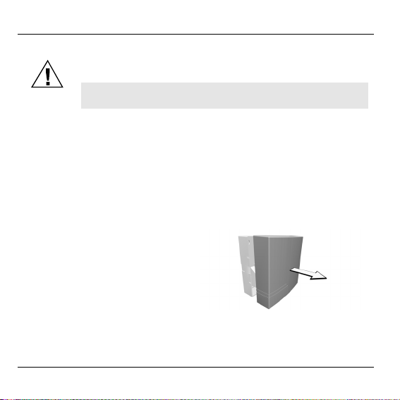
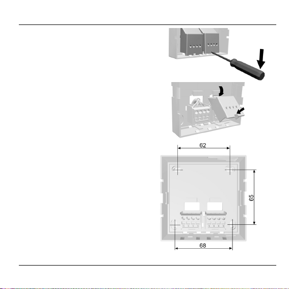
► Gehäuseabdeckung des
einen anderen Montageort.
Erweiterungsmoduls HX 85
abnehmen.
12
Page 15
Montage
► Kontaktabdeckungen mit
Schraubendreher abnehmen.
► Kontaktabdeckungen im
Gehäuseboden einklemmen.
► Gehäusesockel montieren.
13
Page 16
Montage
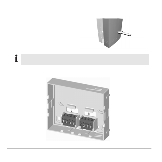
► Gehäuseabdeckung auf den
Gehäuseboden stecken.
Darauf achten, dass die Stifte der Gehäuseabdeckung auf die
Klemmblöcke passen und die Abdeckung einrastet.
Klemmenbelegung
14
4
Page 17
Montage
Klemmenblock L
BA 1 V in Gnd Inp1 Inp2
Versorgungsspannung
12 VAC / 12 VDC
BA 2 Vin Gnd Data* Sync*
Versorgungsspannung
12 VAC / 12 VDC
BA 1 Inp3 Inp4 Inp5 V in
dig. Eingang
DI 3
12 VAC /
12 VDC
BA 2 nicht belegt nicht belegt nicht belegt nicht belegt
Masse dig. Eingang
DI 1
12 VAC /
12 VDC
Masse Data (13) Sync (14)
Klemmenblock R
dig. Eingang
DI 4
12 VAC /
12 VDC
dig. Eingang
DI 5
12 VAC /
12 VDC
dig. Eigang
DI 2
12 VAC /
12 VDC
Versorgungsspannung
12 VAC /
12 VDC
15
Page 18
Montage
Betriebsart einstellen
► Mit den DIP-Schaltern auf der Platine der Gehäuseabdeckung die
gewünschte Betriebsart einstellen (siehe Seite 5).
Betriebsart 2 ist nur mit HCM 200D möglich.
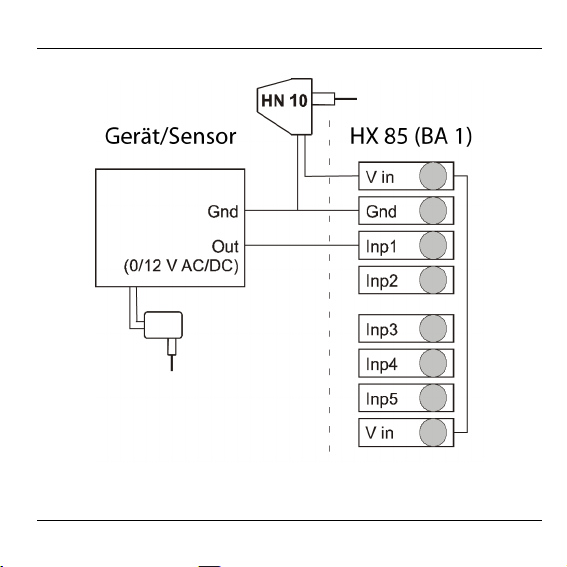
Geräte/Sensor an HX 85 anschließen
Am Erweiterungsmodul können sowohl Fühler, Ausgänge von
Alarmanlagen als auch Schalter angeschlossen werden. Die
folgenden Abbildungen zeigt die prinzipiellen Anschlussmöglichkeiten
für beide Betriebsarten.
16
Page 19
Montage
Gerät/Sensor mit 0V/12V Ausgang
17
Page 20
Montage
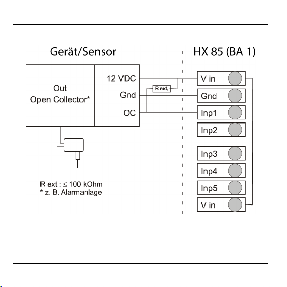
Gerät/Sensor mit Open Collector Ausgang
18
Page 21
Montage
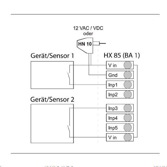
Gerät/Sensor mit potentialfreiem Relaiskontakt
19
Page 22
Montage
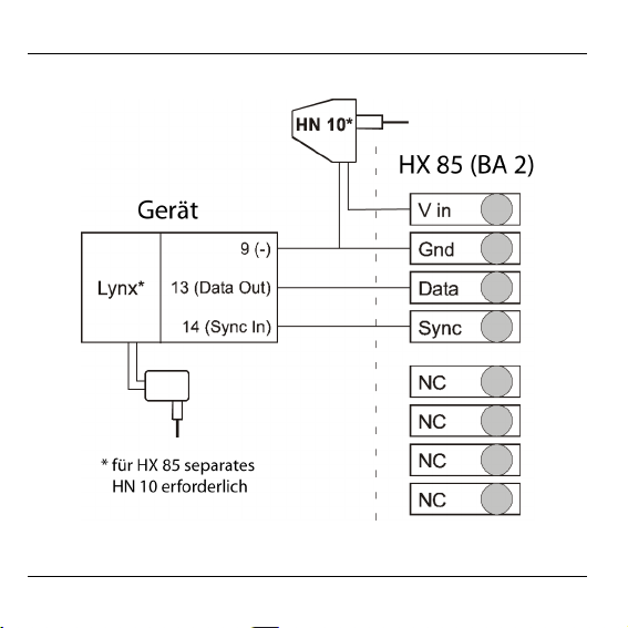
Alarmanlage (nur mit HCM 200D möglich)
20
Page 23
Teach-in
Teach-in
Teach-in am Hometronic Manager aktivieren
In das Untermenü "Installation" wechseln
► Das Display zeigt die Standard
Anzeige, z. B.:
► Eingabeknopf am Hometronic
Manager drücken.
Im Display erscheint:
► Eingabeknopf nach rechts
drehen, um den Cursor in die
oberste Zeile zu bewegen.
Im Display erscheint:
► Eingabeknopf drücken.
Im Display erscheint:
21
Hometronic
DO 01.03.2007 11:15
Kein Lifestyle aktiv
WOHNEN 20.0 C
MENÜ
DATUM/ZEIT STELLEN
LIFESTYLE AKTIVIEREN
WOHNEN 20.0 C
MENÜ
DATUM/ZEIT STELLEN
LIFESTYLE AKTIVIEREN
WOHNEN 20.0 C
LIFESTYLES
ZEITPROGRAMME
ANZEIGE
EINSTELLUNGEN
Page 24
Teach-in
► Eingabeknopf nach links
drehen, bis der Menüpunkt
"Einstellungen" markiert ist.
Im Display erscheint:
► Eingabeknopf zweimal drücken.
Im Display erscheint:
Das Untermenü "Installation" ist angewählt.
► Eingabeknopf nach links
drehen, bis der Menüpunkt
"Fühler" markiert ist.
Im Display erscheint:
► Eingabeknopf drücken
Im Display erscheint:
In diesem Fall sind die Fühler
1–4(5) frei.
LIFESTYLES
ZEITPROGRAMME
ANZEIGE
EINSTELLUNGEN
HEIZUNG
ROLLADEN
GERÄTE/LICHT
FÜHLER
HEIZUNG
ROLLADEN
GERÄTE/LICHT
FÜHLER
FÜHLER-1
FÜHLER-2
FÜHLER-3
FÜHLER-4
Möglichst den freien Fühler in der Liste wählen, der
nachfolgend die Installation von 5 Fühlern hintereinander
zulässt.
22
Page 25
Teach-in
► Eingabeknopf drücken.
In der markierten Zeile blinkt rechts
der Cursor.
FÜHLER-1 C
FÜHLER-2
FÜHLER-3
FÜHLER-4
Teach-in am Erweiterungsmodul HX 85 durchführen
► Taste am Erweiterungsmodul
mindestens 5 Sekunden drücken.
Die in die Taste integrierte grüne
LED leuchtet und erlischt kurzzeitig
nach 5 Sekunden.
Im HCM 200D Display erscheint für
jeden Fühler kurzzeitig ein * und
dann die Meldung DIGITAL.
Insgesamt werden 5 Fühler
installiert.
Haben Sie weniger als 5 Fühler verdrahtet, wird empfohlen,
die überzähligen zu deinstallieren (siehe Abschnitt "Fühler
deinstallieren", Seite 25).
23
FÜHLER-1 DIGITAL
FÜHLER-2 DIGITAL
FÜHLER-3 DIGITAL
FÜHLER-4 DIGITAL
Page 26
Teach-in
Erfolgreicher Teach-in
War der Teach-in erfolgreich, wird
wie vorangehend beschrieben, im
Installationsmenü des HCM 200D
für 5 Fühler folgender Status
angezeigt:
FÜHLER-1 DIGITAL
FÜHLER-2 DIGITAL
FÜHLER-3 DIGITAL
FÜHLER-4 DIGITAL
Misslungener Teach-in
Wenn für einen Fühler ein * oder nichts angezeigt wird, ist der
Teach-in misslungen.
► Übertragung verbessern, Störungen oder Abschirmungen
vermeiden, z. B. durch:
– Drahtlose Kopfhörer, Garagentoröffner,
Fernbedienungen, Metallteile
– Wenn möglich, die Position des Erweiterungsmoduls
ändern.
► Teach-in wiederholen (siehe ab Seite 21).
24
Page 27
Fühler deinstallieren
Fühler deinstallieren
Standardmäßig werden beim Teach-in für ein Erweiterungsmodul
5 Fühler installiert. Haben Sie weniger als 5 Fühler verdrahtet, wird
empfohlen, die überzähligen Fühler zu deinstallieren.
In das Untermenü "Deinstallation" wechseln
► Das Display zeigt die Standard
Anzeige, z. B.:
► Eingabeknopf am Hometronic
Manager drücken.
Im Display erscheint:
► Eingabeknopf nach rechts
drehen, um den Cursor in die
oberste Zeile zu bewegen.
Im Display erscheint:
► Eingabeknopf drücken.
Im Display erscheint:
25
Hometronic
DO 01.03.2007 11:15
Kein Lifestyle aktiv
WOHNEN 20.0 C
MENÜ
DATUM/ZEIT STELLEN
LIFESTYLE AKTIVIEREN
WOHNEN 20.0 C
MENÜ
DATUM/ZEIT STELLEN
LIFESTYLE AKTIVIEREN
WOHNEN 20.0 C
LIFESTYLES
ZEITPROGRAMME
ANZEIGE
EINSTELLUNGEN
Page 28
Fühler deinstallieren
► Eingabeknopf nach links
drehen, bis der Menüpunkt
"Einstellungen" markiert ist.
Im Display erscheint:
► Eingabeknopf drücken.
Im Display erscheint:
► Eingabeknopf nach links drehen,
bis der Menüpunkt
"DEINSTALLATION" markiert ist.
Im Display erscheint:
► Eingabeknopf drücken.
Im Display erscheint:
► Eingabeknopf nach links
drehen, bis der Menüpunkt
"FÜHLER" markiert ist.
Im Display erscheint:
26
LIFESTYLES
ZEITPROGRAMME
ANZEIGE
EINSTELLUNGEN
INSTALLATION
DE-INSTALLATION
FUNKTION ERWEITERUNG
FÜHLERFUNKTION
INSTALLATION
DE-INSTALLATION
FUNKTION ERWEITERUNG
FÜHLERFUNKTION
HEIZUNG
ROLLÄDEN
GERÄTE/LICHT
FÜHLER
HEIZUNG
ROLLÄDEN
GERÄTE/LICHT
FÜHLER
Page 29
Fühler deinstallieren
► Eingabeknopf drücken.
Im Display erscheint:
► Eingabeknopf nach links bzw. rechts
drehen, um den Fühler zu markieren,
der deinstalliert werden soll, in
diesem Fall Fühler 3.
Im Display erscheint:
► Eingabeknopf drücken.
Im Display erscheint:
Der entsprechende Fühler, in diesem Fall Fühler 3, wurde
FÜHLER-1 DIGITAL
FÜHLER-2 DIGITAL
FÜHLER-3 DIGITAL
FÜHLER-4 DIGITAL
FÜHLER-1 DIGITAL
FÜHLER-2 DIGITAL
FÜHLER-3 DIGITAL
FÜHLER-4 DIGITAL
FÜHLER-1 DIGITAL
FÜHLER-2 DIGITAL
FÜHLER-4 DIGITAL
FÜHLER-5 DIGITAL
deinstalliert.
27
Page 30

Lifestyles zuordnen
Lifestyles zuordnen
Jedem DI bzw. jeder Geräteadresse A1..A5 lässt sich im HCM 200D
ein entsprechender Lifestyle zuordnen, der ausgelöst wird, sobald an
diesem Eingang ein Statuswechsel stattgefunden hat. Lifestyles
werden einem Fühler als Nummer zugeordnet. Bitte merken Sie sich
daher im Untermenü "Lifestyles" die Position des Lifestyles, den Sie
zuordnen möchten.
In das Untermenü "Erweiterungsmodule" wechseln
► Das Display zeigt die Standard
Anzeige, z. B.:
► Eingabeknopf am Hometronic
Manager drücken.
Im Display erscheint:
► Eingabeknopf nach rechts
drehen, um den Cursor in die
oberste Zeile zu bewegen.
Im Display erscheint:
28
Hometronic
DO 01.03.2007 11:15
Kein Lifestyle aktiv
WOHNEN 20.0 C
MENÜ
DATUM/ZEIT STELLEN
LIFESTYLE AKTIVIEREN
WOHNEN 20.0 C
MENÜ
DATUM/ZEIT STELLEN
LIFESTYLE AKTIVIEREN
WOHNEN 20.0 C
Page 31

Lifestyles zuordnen
► Eingabeknopf drücken.
Im Display erscheint:
► Eingabeknopf nach links
drehen, bis der Menüpunkt
"Einstellungen" markiert ist.
Im Display erscheint:
► Eingabeknopf drücken.
Im Display erscheint:
► Eingabeknopf nach links
drehen, bis der Menüpunkt
"ERWEITERUNGSMODULE"
markiert ist.
Im Display erscheint:
► Eingabeknopf drücken.
Im Display erscheint:
LIFESTYLES
ZEITPROGRAMME
ANZEIGE
EINSTELLUNGEN
LIFESTYLES
ZEITPROGRAMME
ANZEIGE
EINSTELLUNGEN
INSTALLATION
DE INSTALLATION
FUNKTION ERWEITERUNG
FÜHLERFUNKTION
NAMEN ÄNDERN
KONFIGURATION
HEIZ.-REGLER SPERREN
ERWEITERUNGSMODULE
Lifestyle zuordnen:
FÜHLER-1 ↓ LS 0
FÜHLER-1 ↑ LS 0
FÜHLER-2 ↓ LS 0
29
Page 32

Lifestyles zuordnen
Für jeden Fühler kann sowohl bei fallender ↓ als auch
ansteigender ↑ Flanke des Statuswechsels ein individueller
Lifestyle zugeordnet werden.
► Eingabeknopf nach links bzw. rechts
drehen, um den gewünschten Fühler
mit entsprechendem Flankenwechsel
zu markieren.
Im Display erscheint z. B.:
► Eingabeknopf drücken.
Im Display erscheint:
Lifestyle zuordnen:
FÜHLER-1 ↓ LS 0
FÜHLER-1 ↑ LS 0
FÜHLER-2 ↓ LS 0
Lifestyle zuordnen:
FÜHLER-1 ↓ LS 0
FÜHLER-1 ↑ LS 0
► Eingabeknopf nach rechts drehen
und die gewünschte Lifestylenummer
einstellen. Eingabeknopf drücken.
Im Display erscheint z. B.:
Dem Fühler 1 wurde Lifestyle 5
FÜHLER-2 ↓ LS 0
Lifestyle zuordnen:
FÜHLER-1 ↓ LS 0
FÜHLER-1 ↑ LS 5
FÜHLER-2 ↓ LS 0
zugeordnet, der bei ansteigender
Flanke ausgelöst wird.
30
Page 33

Digitale Eingänge/X-10 Kommandos prüfen
Digitale Eingänge/X-10 Kommandos prüfen
Das Erweiterungsmodul HX 85 ermöglicht nach erfolgreichem Teachin eine Funktionsprüfung.
► Am HCM 200D ins Menü "Anzeige/Fühlerwerte" wechseln.
► Am HX 85 die Taste mindestens 10 Sekunden drücken.
Die in die Taste integrierte grüne LED zeigt folgendes
Leuchtverhalten.
Nach 10 Sekunden ist das Erweiterungsmodul im Testmodus.
31
Page 34

Status der digitalen Eingänge senden
Die Funktionsprüfung kann nun max. 10 Minuten lang
durchgeführt werden.
► Statuswechsel am jeweiligen digitalen Eingang bzw. über die
Alarmanlage an der jeweiligen Geräteadresse auslösen.
Ändert sich der Status am DI bzw. an der Geräteadresse A,
leuchtet am Erweiterungsmodul kurz die grüne LED und zeigt
damit an, dass ein Statuswechsel an den HCM 200D gesendet
wurde. Am HCM 200D kann der Statuswechsel für die Fühler im
Menü "Anzeige/Fühlerwerte" durch JA-NEIN-Wechsel verfolgt
werden.
Beachten Sie in diesem Zusammenhang auch die Zuordnung
der Lifestyles zu den jeweiligen Eingängen (siehe Seite 28)
Status der digitalen Eingänge senden
Der aktuellen Status der digitalen Eingänge kann per Tastendruck
gesendet werden.
► Am HX 85 die Taste ca. 2 Sekunden drücken, bis die in die Taste
integrierte grüne LED leuchtet.
Der Status wurden gesendet.
32
Page 35

Glossar
Glossar
Betriebsart
Eine von zwei Betriebsarten (BA 1,
BA2), die für HX 85 zum einen die
Verarbeitung von Signalen von verdrahteten Gebern und zum anderen
die X-10-protokollunterstützte
Kommunikation mit Alarmanlagen
zulässt.
Data
Port zur Datenübertragung der X-10
Schnittstelle.
Hauscode
Spezifizierter Code für
Alarmanlagen, die über das
Stromnetz kommunizieren.
Priorität
Einstellung des digitalen Eingangs
DI1 oder der Geräteadresse A1.
Durch Vergabe der Priorität lassen
sich sowohl in der BA 1 als auch in
der BA 2 Alarmmeldungen
vorzugsweise behandeln. Der
auslösende Alarm wird nicht durch
33
Aktivierung anderer Lifestyles
unterbrochen.
Status
Zustand (0 oder 1) eines digitalen
Eingangs.
Statuswechsel
Zustandswechsel an einem digitalen Eingang von 0→1 oder 1→0.
Wechsel an einer Geräteadresse
von OFF→ON oder ON→OFF.
Sync
Port zur Synchronisation der
Datenübertragung der X-10
Schnittstelle.
Teach-in
Vorgang der Zuordnung des
Erweiterungsmoduls HX 85 zum
Hometronic Manager oder einem
anderen Gerät.
X-10 Schnittstelle
Schnittstelle zu ADEMCO
Alarmanlagen (Lynx).
Page 36

Technische Daten
Technische Daten
Betriebsspannung 12 VAC / VDC ± 20 %
Max. Stromaufnahme 40 mA (AC), 20 mA (DC)
Spannung DI 12 VAC / VDC ± 20 %
Max. Pullup-Widerstand an DI
Betriebstemperatur 0...40 °C
Schutzklasse IP 20
Lagertemperatur –20 °C...+70 °C
Max.Luftfeuchtigkeit 95 %, nicht kondensierend
Digitale Eingänge 5
Schnittstelle X-10
Min. Sendepause:
- zwischen 2 Statuswechseln
- bei ausgelöstem Lifestyle 17
Netzteil HN 10
Sender 868,3 MHz
Max. Kabellänge 30 m
100 kΩ (DC)
10 s
ca. 1 min
34
Page 37

Hilfe im Problemfall
Hilfe im Problemfall
Problem/Anzeige Ursache Lösung
Anzeige von
Sternchen "*" im
Menü "Installation"
des HCM 200D
Anzeige von
Ausrufezeichen "!"
im Hauptmenü des
HCM 200D
Teach-in
misslungen
Keine Versorgungsspannung am
HX 85
Funkverbindung ist
seit 3 Stunden
Siehe „Übertragung
verbessern" (Seite 24).
Teach-in wiederholen.
Versorgungsspannung
anlegen (Seite 16).
Siehe „Übertragung
verbessern" (Seite 24).
gestört
Verzögertes
Ausführen eines
Statuswechsels
Zu häufige
Statuswechsel
innerhalb der
Zeitintervall zwischen
2 Statuswechseln
vergrößern.
Sendepause von
10 s
Verzögertes
Ausführen eines
Statuswechsels
Ausgelöster Lifestyle, z. B. LS 17,
beinhaltet viele
Zeitintervall zwischen 2
Ereignissen am HX 85
vergrößern.
Aktionen
35
Page 38

Hilfe im Problemfall
Problem/Anzeige Ursache Lösung
Meldung "Kein
Lifestyle aktiv" im
HCM 200D
Keine Steuerung
durch Hometronic
Manager
36
Einem Lifestyle
wurde kein Modul
zugeordnet.
HINWEIS: Diese
Meldung erscheint
auch, wenn einem
Eingang oder einer
Geräteadresse
Lifestyle 17
zugeordnet wurde
(Standardmeldung
im Automatikbetrieb)
Funkverbindung ist
gestört
Modul zuordnen, siehe
"Einem Lifestyle ein
Modul oder einen Raum
zuordnen" in
Bedienungsanleitung
HCM 200D.
Siehe „Übertragung
verbessern" (Seite 24).
Page 39

Contents
Contents
Application 38
Operating modes 39
Communication with HCM 200D 43
Installation procedure 46
Mounting 47
Terminal assignment 49
Setting operating mode 51
Connecting devices/sensor to HX 85 51
Device/sensor with 0 V/12 V output 52
Device/sensor with open collector output 53
Binding 56
Activating binding at Hometronic Manager 56
Execute binding at Expansion Module HX 85 58
De-installing sensors 60
Assigning lifestyles 63
Checking digital inputs/X-10 commands 66
Transmitting status of the digital inputs 67
Glossary 68
Technical data 69
Help with problems 70
37
Page 40

Application
For your information
Technical terms are explained in the glossary (Page 68).
Application
The Module HX 85 has two different operating modes that can be set
either as a sensor or Lynx alarm system, depending on the
application. In all, five digital inputs are available. Operating mode 1
allows the processing of five digital inputs, and operating mode 2
allows communication with ADEMCO alarm systems (Lynx) via the X10 interface. The respective operating mode is set via DIP switches.
Operating mode 2 is only possible with HCM 200D.
The status of a digital input is indicated via YES-NO in the HCM 200D.
Each state change of a digital input can be assigned a corresponding
lifestyle at the Hometronic Manager HCM 200D.
38
Page 41

Operating modes
Operating modes
For the purposes of the HCM 200D, operating mode 1 functions in the
same manner for processing of five digital inputs as operating mode 2
does for the integration of the ADEMCO alarm system. Digital inputs
1–5 correspond to device addresses A1–A5 of the X-10 protocol, i.e.
the first sensor input corresponds to A1, the second to A2 etc.
Only one of the two operating modes B1 and B2 can be
selected. Operating mode B2 is only possible with HCM 200D.
Address assignment
OM 1 (DI) OM 2 (Operating Mode 2) (X-10), only
1 House code: A / key code: 1
2 House code: A / key code: 2
3 House code: A / key code: 3
4 House code: A / key code: 4
5 House code: A / key code: 5
39
possible in conjunction with HCM 200D
Page 42

Operating modes
When programming the alarm system, it must be ensured that
house code A is used to trigger the alarm for OM 2.
Assignment table between input voltage and operating mode
DI voltage OM 1 (DI) OM 2 (X-10)
0 V Low (0) OFF
12 V AC/DC High (1) ON
Setting operating mode and priority*
The operating mode setting includes the specification of operating
mode 1 or 2 and the general setting of the priority for the digital input
DI1 or device address A1.
The priority can only be specified for DI1 or A1.
By issuing priority, alarms can be handled with preference both in OM
1 and OM 2.
If DI1 or device address A1 is set to priority, the status of the DI1 is
transferred cyclically (2 min ±30 s) until the cause of the alarm is
suppressed. At the HCM 200D, the lifestyle triggered by the alarm is
continually reactivated.
40
Page 43

Operating modes
The signal is transmitted cyclically based on the input signal and the
priority.
DI input signal Priority
0 0 OM 1
1 1
ON ON OM 2
Signal
transmitted
cyclically
OFF OFF
If DI1 is not set to priority, the status of an input is transmitted after
each state change* by default.
41
Page 44

Operating modes
Priority and operating mode are set
via four DIP switches as follows:
No. 1 2 3 4 Note
Function Priority OM -
OM 1 OFF OFF OFF OFF No priority set1
ON OFF OFF OFF Priority 0
OFF ON OFF OFF Priority 1
OM 2 OFF OFF ON OFF No priority set
ON OFF ON OFF Priority OFF
OFF ON ON OFF Priority ON
1
All other DIP switch combinations function as OFF.
42
Page 45

Operating modes
Communication with HCM 200D
The Expansion Module HX 85 transmits immediately as soon as an
input state changes.
The following table shows the correlation between the status display
of the HCM 200D and the inputs.
OM 1
digital
inputs
DI 1: 1 -> 0 A1 = ON -> OFF NO
DI 1: 0 -> 1 A1 = OFF-> ON YES
DI 2: 1 -> 0 A2 = ON -> OFF NO
DI 2: 0 -> 1 A2 = OFF-> ON YES
DI 3: 1 -> 0 A3 = ON -> OFF NO
DI 3: 0 -> 1 A3 = OFF-> ON YES
DI 4: 1 -> 0 A4 = ON -> OFF NO
DI 4: 0 -> 1 A4 = OFF-> ON YES
DI 5: 1 -> 0 A5 = ON -> OFF NO
DI 5: 0 -> 1 A5 = OFF-> ON YES
Binding (installation)
The digital inputs are installed as sensors in the HCM 200D. Each
expansion module always occupies five sensor slots during
installation.
OM 2
X-10 interface
device address + data
HCM200
status
display
Edge for
lifestyle
activation
↓
↑
↓
↑
↓
↑
↓
↑
↓
↑
43
Page 46

Operating modes
Example:
Installation of one Module HX 85 with 1 x 5 sensors with three sensors
already installed (slots 1–3).
Sensor slot Installation De-installation Installed sensors
Outside temp. ...
Bright ....
Wind .....
Sensor 4 HX 85 (1) Sensor 4
Sensor 5 Sensor 5
Sensor 6 5 sensors Sensor 6
Sensor 7 Sensor 7
Sensor 8 Sensor 8
When an expansion module is installed, the HCM 200D only
immediately shows the current states at the digital inputs in operating
mode 1. In operating mode 2, all inputs are set to "--" during
commissioning and when binding occurs, as no X-10 commands have
been received yet.
The sensor names can be edited and converted into a question. For
example:
Alarm: YES
Skylight closed? NO
Valve closed? YES
44
Page 47

Operating modes
Assigning lifestyles (HCM 200D)
Each change in state can be assigned a corresponding lifestyle in the
HCM 200D. If lifestyle 0 is assigned, nothing changes when it is
activated. If lifestyle 17 is assigned, switching to automatic mode
occurs when it is activated.
The default setting of the assignment of the input state to the lifestyle
number is "0".
An assigned lifestyle is then only displayed and executed in
the HCM 200D if at least one action, e.g. "Switch on device",
has been programmed for the lifestyle.
Lifestyles are assigned in the "Settings/Expansion Modules" menu.
45
Page 48

Installation procedure
Installation procedure
Mounting
• Mount HX 85
• Connect devices to HX 85
• Set operating mode at DIP switches
Binding (install sensors)
• Activate binding at the HCM 200D (or other operating devices)
• Execute binding at the HX 85
Assigning lifestyles (optional)
A lifestyle that is triggered when a state change occurs can be
assigned to a digital input (X-10) or a device address at the
HCM 200D.
Transmitting status of the digital inputs
The current states of the digital inputs can be transmitted to the
HCM 200D with the press of a button on the HX 85.
46
Page 49

Mounting
Mounting
Insufficient data transfer!
Warning!
Interference of the radio transmitter in the device by
metallic objects and other radio devices.
► When selecting the operating site ensure that the
distance to radio devices such as radio headphones,
cordless phones, etc. according to the DECT standard
is at least 1 m.
► Ensure that there is sufficient distance to metallic
objects.
► Select another mounting site if the radio interference
► Remove the housing cover of
cannot be rectified.
the Expansion Module HX 85.
47
Page 50

Mounting
► Remove the contact covers
with a screwdriver.
► Clamp the contact covers in
the housing bottom.
► Mount the housing base.
48
Page 51

Mounting
► Fit the housing cover onto the
housing bottom.
Ensure that the pins of the housing cover fit onto the terminal
block and that the cover engages.
Terminal assignment
4
49
Page 52

Mounting
Terminal block L
OM 1 V in Gnd Inp1 Inp2
Supply voltage
12 V AC / 12 V DC
OM 2 V in Gnd Data* Sync*
Supply voltage
12 V AC / 12 V DC
OM 1 Inp3 Inp4 Inp5 V in
Dig. input
DI 3
12 V AC /
12 V DC
OM 2 not assigned not assigned not assigned not assigned
Earth Dig. input
DI 1
12 V AC /
12 V DC
Earth Data (13) Sync (14)
Terminal block R
Dig. input
DI 4
12 V AC /
12 V DC
Dig. input
DI 5
12 V AC /
12 V DC
Dig. input DI
2
12 V AC /
12 V DC
Supply
voltage
12 V AC /
12 V DC
50
Page 53

Mounting
Setting operating mode
► Set the desired operating mode with the DIP switches on the PCB of
the housing cover (see Page 40).
Operating mode 2 is only possible with HCM 200D.
Connecting devices/sensor to HX 85
Sensors, outputs of alarm systems and switches can all be connected
to the expansion module The following figures show the principle
connection options for both operating modes.
51
Page 54

Mounting
Device/sensor with 0 V/12 V output
52
Page 55

Mounting
Device/sensor with open collector output
53
Page 56

Mounting
Device/sensor with floating relay contact
54
Page 57

Mounting
Alarm system (only possible with HCM 200D)
55
Page 58

Binding
Binding
Activating binding at Hometronic Manager
Switching to the "Installation" submenu
► The display shows the default
display, e.g.:
► Press the Input button on the
Hometronic Manager.
The following is displayed:
► Turn the Input button to the right
in order to move the cursor to
the top line.
The following is displayed:
► Press the Input button.
The following is displayed:
56
Hometronic
TU 14.05.2007 10:00
No lifestyle active
LIVING 20.0 C
MENÜ
SET DATE/TIME
ACTIVATE LIFESTYLE
LIVING. 20.0 C
MENÜ
SET DATE/TIME
ACTIVATE LIFESTYLE
LIVING 20.0 C
LIFESTYLES
TIME PROGRAMS
DISPLAY
SETTINGS
Page 59

Binding
► Turn the Input button to the left
until the "Settings" menu item is
selected.
The following is displayed:
► Press the Input button twice.
The following is displayed:
The "Installation" submenu is selected.
► Turn the Input button to the left
until the "Sensor" menu item is
selected.
The following is displayed:
► Press the Input button.
The following is displayed:
In this case, sensors 1–4 (5)
are available.
LIFESTYLES
TIME PROGRAMS
DISPLAY
SETTINGS
HEATING
SHUTTER
DEVICES/LIGHT
SENSOR
HEATING
SHUTTER
DEVICES/LIGHT
SENSOR
SENSOR -1
SENSOR -2
SENSOR -3
SENSOR -4
If possible, select the available sensor in the list that
subsequently allows the installation of five sensors in
succession.
57
Page 60

Binding
► Press the Input button.
The cursor flashes to the right on the
selected line.
SENSOR -1
C
SENSOR -2
SENSOR -3
SENSOR -4
Execute binding at Expansion Module HX 85
► Press the button on the expansion module for at least 5 seconds.
The green LED integrated in the button illuminates and goes out
briefly after 5 seconds.
An * and then the message DIGITAL
briefly appear for each sensor in the
HCM 200D display. Altogether,
5 sensors are installed.
SENSOR -1 DIGITAL
SENSOR -2 DIGITAL
SENSOR -3 DIGITAL
SENSOR -4 DIGITAL
If you have wired fewer than five sensors, we recommend deinstalling the redundant ones (see the De-installing sensors
section, Page 60)
58
Page 61

Binding
Successful binding
If binding was successful, the
following status is displayed for five
sensors in the installation menu of
the HCM 200D as described
SENSOR -1 DIGITAL
SENSOR -2 DIGITAL
SENSOR -3 DIGITAL
SENSOR -4 DIGITAL
above:
Failed binding
If either * or nothing at all is displayed for a sensor, binding
has failed.
► Improve data transfer, avoid disturbances or shielding, for
example, caused by:
– Radio headphones, garage door openers, remote
controls, metal parts
– If possible, change the position of the expansion
module.
► Repeat binding (starting on Page 56).
59
Page 62

De-installing sensors
De-installing sensors
By default, five sensors are installed when binding an expansion
module. If you have wired fewer than five sensors, we recommend deinstalling the redundant sensors.
Switching to the "De-installation" submenu
► The display shows the default
display, e.g.:
► Press the Input button on the
Hometronic Manager.
The following is displayed:
► Turn the Input button to the right
in order to move the cursor to
the top line.
The following is displayed:
► Press the Input button.
The following is displayed:
60
Hometronic
TU 14.05.2007 10:00
No lifestyle active
LIVING 20.0 C
MENÜ
SET DATE/TIME
ACTIVATE LIFESTYLE
LIVING. 20.0 C
MENÜ
SET DATE/TIME
ACTIVATE LIFESTYLE
LIVING 20.0 C
LIFESTYLES
TIME PROGRAMS
DISPLAY
SETTINGS
Page 63

De-installing sensors
► Turn the Input button to the
left until the "Settings" menu
item is selected.
The following is displayed:
► Press the Input button.
The following is displayed:
► Turn the Input button to the
left until the "DEINSTALLATION" menu item is
selected.
The following is displayed:
► Press the Input button.
The following is displayed:
► Turn the Input button to the
left until the "SENSOR" menu
item is selected.
The following is displayed:
LIFESTYLES
TIME PROGRAMS
DISPLAY
SETTINGS
INSTALLATION
DE-INSTALLATION
EXTENSION FUNCTION
SENSOR FUNCTION
INSTALLATION
DE-INSTALLATION
EXTENSION FUNCTION
SENSOR FUNCTION
HEATING
SHUTTER
DEVICES/LIGHT
SENSOR
HEATING
SHUTTER
DEVICES/LIGHT
SENSOR
61
Page 64

De-installing sensors
► Press the Input button.
The following is displayed:
► Turn the Input button to the left or
right to select the sensor to be
de-installed; in this case, sensor 3.
The following is displayed:
► Press the Input button.
The following is displayed:
The corresponding sensor, in this case sensor 3, has been
SENSOR -1 DIGITAL
SENSOR -2 DIGITAL
SENSOR -3 DIGITAL
SENSOR -4 DIGITAL
SENSOR -1 DIGITAL
SENSOR -2 DIGITAL
SENSOR -3 DIGITAL
SENSOR -4 DIGITAL
SENSOR -1 DIGITAL
SENSOR -2 DIGITAL
SENSOR -4 DIGITAL
SENSOR -5 DIGITAL
de-installed.
62
Page 65

Assigning lifestyles
Assigning lifestyles
Each DI or device address A1..A5 can be assigned a corresponding
lifestyle in the HCM 200D that is triggered as soon as a change of
state has occurred at this output. Lifestyles are assigned to a sensor
as a number. For this reason, please take note of the position of the
lifestyle that you would like to assign in the "Lifestyles" submenu.
Switch to the "Expansion Modules" submenu
► The display shows the default
display, e.g.:
► Press the Input button on the
Hometronic Manager.
The following is displayed:
► Turn the Input button to the right
in order to move the cursor to
the top line.
The following is displayed:
63
Hometronic
TU 14.05.2007 10:00
No lifestyle active
LIVING 20.0 C
MENÜ
SET DATE/TIME
ACTIVATE LIFESTYLE
LIVING. 20.0 C
MENÜ
SET DATE/TIME
ACTIVATE LIFESTYLE
LIVING 20.0 C
Page 66

Assigning lifestyles
► Press the Input button.
The following is displayed:
► Turn the Input button to the
left until the "Settings" menu
item is selected.
The following is displayed:
► Press the Input button.
The following is displayed:
► Turn the Input button to the
left until the "EXPANSION
MODULES" menu item is
selected.
The following is displayed:
► Press the Input button.
The following is displayed:
64
LIFESTYLES
TIME PROGRAMS
DISPLAY
SETTINGS
LIFESTYLES
TIME PROGRAMS
DISPLAY
SETTINGS
INSTALLATION
DE-INSTALLATION
EXTENSION FUNCTION
SENSOR FUNCTION
CHANGE NAMES
CONFIGURATION
LOCAL OPERATION LOCK
EXPANSION MODULES
Assign lifestyles:
SENSOR -1 ↓ LS 0
SENSOR -1 ↑ LS 0
SENSOR -2 ↓ LS 0
Page 67

Assigning lifestyles
A unique lifestyle can be assigned for each sensor with either
a falling ↓ or a rising ↑ edge of the state change.
► Turn the Input button to the left or
right to select the desired sensor
with the corresponding edge
change.
The following is displayed, e.g.:
► Press the Input button.
The following is displayed:
Assign lifestyles:
SENSOR -1 ↓ LS 0
SENSOR -1 ↑ LS 0
SENSOR -2 ↓ LS 0
Assign lifestyles:
SENSOR -1 ↓ LS 0
SENSOR -1 ↑ LS 0
► Turn the Input button to the right
and set the desired lifestyle
number. Press the Input button.
The following is displayed, e.g.:
Lifestyle 5 has been assigned to
SENSOR -2 ↓ LS 0
Assign lifestyles:
SENSOR -1 ↓ LS 0
SENSOR -1 ↑ LS 5
SENSOR -2 ↓ LS 0
sensor 1 and is triggered with a
rising edge.
65
Page 68

Checking digital inputs/X-10 commands
Checking digital inputs/X-10 commands
The Expansion Module HX 85 enables an operational test to be
carried out after binding.
► Switch to the "Display/Sensor Values" menu at the HCM 200D.
► Press and hold the button on the HX 85 for at least 10 seconds.
The green LED integrated in the button exhibits the following
illumination behaviour.
The expansion module is in test mode after 10 seconds.
66
Page 69

Transmitting status of the digital inputs
The operational test can now be performed for a maximum of
10 minutes.
► Trigger a state change at the respective digital input or via the alarm
system at the respective device address.
If the state at the DI or device address A changes, the green LED
on the expansion module illuminates briefly, thus indicating that a
state change has been transmitted to the HCM 200D. The state
change for the sensors can be tracked via YES-NO switching in
the "Display/Sensor Values" menu at the HCM 200D.
In this context, also note the assignment to the respective
inputs (see Page 63).
Transmitting status of the digital inputs
The current status of the digital inputs can be transmitted with the
push of a button.
► Press and hold the button on the HX 85 for approx. 2 seconds until
the green LED integrated in the button illuminates.
The status has been transmitted.
67
Page 70

Glossary
Glossary
Binding
Procedure for assigning the Expansion Module HX 85 to the Hometronic Manager or another device.
Data
Port for data transfer via the X-10
interface.
House code
Specified code for alarm systems
that communicate via the mains
network.
Operating mode
One of two operating modes
(OM 1 and OM 2) that allows both
the processing of signals from
wired sensors as well as X-10
protocol-supported communication for
HX 80.
68
Priority
Setting of the digital input DI1 or
device address A1. By issuing
priority, alarm messages can be
handled with preference both in
OM 1 and OM 2. The triggering
alarm is not interrupted by activation of another lifestyle.
Status
State (0 or 1) of a digital input.
State change
State change at a digital input from
0 → 1 or 1 → 0. Change at a device
address from OFF → ON or ON →
OFF.
Sync
Port for synchronisation of the data
transfer via the X-10 interface.
X-10 interface
Interface to ADEMCO alarm systems (Lynx).
Page 71

Technical data
Technical data
Operating voltage 12 V AC / V DC ±20 %
Max. current consumption 40 mA (AC), 20 mA (DC)
DI voltage 12 V AC / V DC ±20 %
Max. pull-up resistance at DI
Operating temperature 0...40 °C
Protection class IP 20
Storage temperature –20 °C...+70 °C
Max. humidity 95 %, non-condensing
Digital inputs 5
Interface X-10
Min. transmission pause:
- between two state changes
- with a triggered lifestyle 17
Power supply unit HN 10
Transmitter 868.3 MHz
Max. cable length 30 m
100 kΩ (DC)
10 seconds
approx. 1 minute
69
Page 72

Help with problems
Help with problems
Problem/Display Cause Remedy
Asterisks "*" appear
in the "Installation"
menu of the
HCM 200D
Exclamation marks
"!" appear in the
Binding failed
Supply voltage to
HX 85 faulty.
See "Improving data
transfer" (Page 59).
Repeat binding.
Apply supply voltage
(Page 51).
main menu of the
HCM 200D
Radio connection
disrupted for
See "Improving data
transfer" (Page 59).
3 hours.
Delayed execution
of a state change
Excessive state
changes within the
10-second
Increase time interval
between two state
changes.
transmission pause.
Delayed execution
of a state change
Triggered lifestyle,
e.g. LS 17, includes
many actions
Increase time interval
between two events at
the HX 85.
70
Page 73

Help with problems
Problem/Display Cause Remedy
"No lifestyle active"
message in
HCM 200D
Hometronic
Manager not
controlling.
No modules have
been assigned to a
lifestyle.
NOTE: This
message also
appears when
lifestyle 17 has been
assigned to an input
or a device address
(default message in
automatic mode).
Radio connection is
disturbed.
Assign module, see
"Assigning a module or
room to a lifestyle" in the
operating instructions of
HCM 200D.
See "Improving data
transfer" (Page 59).
71
Page 74

Page 75

Índice
Índice
Aplicación 74
Modos de funcionamiento 75
Comunicación al HCM 200D 79
Procedimiento para la instalación 82
Montaje 83
Asignación de los bornes 85
Ajuste del modo de funcionamiento 87
Conexión de dispositivos/sensor al HX 85 87
Sincronización 92
Activación de la sincronización en el Hometronic Manager 92
Ejecución de la sincronización en el módulo de extensión HX 8594
Desinstalación de sensores 96
Asignación de Lifestyles 99
Comprobación de entradas digitales/comandos X-10 103
Transmisión del estado de entradas digitales 104
Glosario 105
Interfase para instalaciones de alarma ADEMCO (Lynx). 105
Características técnicas 106
Ayuda en caso de problemas 107
73
Page 76

Aplicación
Indicación de lectura
Los términos técnicos se explican en el glosario (página 105).
Aplicación
El módulo HX 85 tiene dos modos de funcionamiento, que según el
ajuste permiten su utilización como sensor o como instalación de
alarma Lynx. En total están a disposición 5 entradas digitales. El
modo de servicio 1 permite el procesamiento de 5 entradas digitales,
el modo de funcionamiento 2 la comunicación con instalaciones de
alarma ADEMCO (Lynx) a través de la interfase X-10. El respectivo
modo de funcionamiento se ajusta mediante microinterruptores DIP.
El modo de funcionamiento 2 es posible sólo con HCM 200D.
El estado de una entrada digital se indica en el HCM 200D a través
de SI-NO. En el Hometronic Manager HCM 200D puede asignarse un
respectivo LIFESTYLE para cada cambio de estado de una entrada
digital.
74
Page 77

Modos de funcionamiento
Modos de funcionamiento
Para el HCM 200D se comportan igualmente el modo de
funcionamiento 1 para el procesamiento de 5 entradas digitales y el
modo de funcionamiento 2 para la integración de la instalación de
alarma ADEMCO. Las entradas digitales 1–5 corresponden a las
direcciones de aparato A1–A5 del protocolo X-10, es decir, la primera
entrada de sensor corresponde a A1, la segunda entrada de sensor a
A2, etc.
Se puede elegir solamente uno de los dos modos de
funcionamiento B1 ó B2. El modo de funcionamiento B2 es
posible sólo con HCM 200D.
Asignación de direcciones
BA 1 (DI) BA 2 (X-10), sólo posible en conexión con
1 Código casa: A / Código clave: 1
2 Código casa: A / Código clave: 2
3 Código casa: A / Código clave: 3
4 Código casa: A / Código clave: 4
5 Código casa: A / Código clave: 5
75
HCM 200D
Page 78

Modos de funcionamiento
Para el BA 2 debe asegurarse en la programación de la
instalación de alarma, que el código casa A se utilice para el
disparo de la alarma.
Tabla de asignación entre tensión de entrada y modo de
funcionamiento
Tensión DI BA1 (DI) BA2 (X-10)
0V Low (0) OFF
12 VCA / VCC High (1) ON
Ajuste del modo de funcionamiento y prioridad*
El ajuste del modo de funcionamiento abarca la fijación al modo de
funcionamiento 1 ó 2 y el ajuste general de la prioridad para la
entrada digital DI1 ó la dirección de aparato A1.
La prioridad puede fijarse sólo para DI1 ó A1.
La fijación de la prioridad permite tratar preferentemente las alarmas
tanto en el BA 1 como también en el BA 2.
76
Page 79

Modos de funcionamiento
Si el DI1 ó la dirección de aparato A1 se ha asignado a prioridad, el
estado del DI1 se transmite cíclicamente (2 min ±30 s), hasta que se
pare la causa de la alarma. En el HCM 200D, el Lifestyle activado por
la alarma se activa continuamente de nuevo.
La señal se transmite cíclicamente en función de la señal de entrada
y la prioridad.
Señal de entrada DI Prioridad
0 0 BA1
1 1
ON ON BA2
La señal se
transmite
cíclicamente
OFF OFF
Si DI1 no se ha asignado a prioridad, el estado de una entrada se
transmite estándar después de cada cambio de estado*.
77
Page 80

Modos de funcionamiento
La prioridad y el modo de
funcionamiento se ajustan con 4
microinterruptores DIP como sigue:
Nº. 1 2 3 4 Comentario
Función Prioridad BA -
BA 1 OFF OFF OFF OFF Prioridad no asignada1
ON OFF OFF OFF Prioridad 0
OFF ON OFF OFF Prioridad 1
BA 2 OFF OFF ON OFF Prioridad no asignada
ON OFF ON OFF Prioridad OFF
OFF ON ON OFF Prioridad ON
1
Todas las otras combinaciones de microinterruptores DIP actúan
como OFF.
78
Page 81

Modos de funcionamiento
Comunicación al HCM 200D
El módulo de extensión HX 85 transmite sin retardo de tiempo tan
pronto cambia un estado de entrada.
La siguiente tabla muestra la relación que hay entre la indicación de
estado del HCM 200D y las entradas.
BA 1
Entradas
digitales
BA 2
Interfase X-10
Dirección de
HCM200
Indicación
de estado
Flanco para
activar el
Lifestyle
aparato y datos
DI 1: 1 -> 0 A1 = ON -> OFF NO
DI 1: 0 -> 1 A1 = OFF-> ON SI
DI 2: 1 -> 0 A2 = ON -> OFF NO
DI 2: 0 -> 1 A2 = OFF-> ON SI
DI 3: 1 -> 0 A3 = ON -> OFF NO
DI 3: 0 -> 1 A3 = OFF-> ON SI
DI 4: 1 -> 0 A4 = ON -> OFF NO
DI 4: 0 -> 1 A4 = OFF-> ON SI
DI 5: 1 -> 0 A5 = ON -> OFF NO
DI 5: 0 -> 1 A5 = OFF-> ON SI
↓
↑
↓
↑
↓
↑
↓
↑
↓
↑
79
Page 82

Modos de funcionamiento
Sincronización (instalación)
Las entradas digitales se instalan en el HCM 200D como sensores.
Cada módulo de extensión ocupa en la instalación siempre 5 sitios de
sensor.
Ejemplo:
Sitio de sensor Instalación Desinstalación Sensores
instalados
Temp. exterior ...
Soleado ....
Viento .....
Sensor-4 HX 85 (1) Sensor-4
Sensor-5 Sensor-5
Sensor-6 5 sensores Sensor-6
Sensor-7 Sensor-7
Sensor-8 Sensor-8
Después de instalar un módulo de extensión, el HCM 200D indica
sólo en el modo de funcionamiento 1 inmediatamente los estados
actuales en las entradas digitales. En el modo de funcionamiento 2,
todas las entradas se asignan a "--" durante la puesta en servicio y en
una nueva sincronización, debido a que todavía no se recibieron
comandos X-10.
80
Page 83

Modos de funcionamiento
Los nombres de sensor pueden modificarse y transformarse en una
pregunta. Por ejemplo:
Alarma: SI
Tragaluz cerrado ? NO
Válvula cerrada ? SI
Asignación de Lifestyles (HCM 200D)
En el HCM 200D a cada cambio de estado puede asignarse un
respectivo Lifestyle. Si se asigna el Lifestyle 0, en su activación no se
cambia nada. Si se asigna el Lifestyle 17, en su activación se cambia
a servicio automático.
El ajuste por defecto de la asignación estado de entrada a número
Lifestyle es "0".
Un Lifestyle asignado se indica y ejecuta en el HCM 200D,
únicamente si fue programada una acción para el Lifestyle,
p.ej. "Encender el aparato".
Los Lifestyles se asignan en el menú "Ajustes/Módulos expansión".
81
Page 84

Procedimiento para la instalación
Procedimiento para la instalación
Montaje
• Montar el HX 85
• Conectar los dispositivos al HX 85
• Ajustar el modo de funcionamiento con microinterruptores DIP
Sincronización (instalación de sensores)
• Activar la sincronización en el HCM 200D (u otros aparatos de
mando)
• Ejecutar la sincronización en el HX 85
Asignación de Lifestyles (opcional)
En el HCM 200D puede asignarse un Lifestyle a una entrada digital
(X-10) o a una dirección de aparato, que se acciona en un cambio de
estado.
Transmisión del estado de entradas digitales
En el HX 85 pueden transmitirse pulsando un botón los estados
actuales de las entradas digitales al HCM 200D.
82
Page 85

Montaje
Montaje
¡Transmisión de datos deficiente!
¡Advertencia!
Interrupción del radiotransmisor en el dispositivo
mediante objetos metálicos y otros aparatos de
radio.
► Preste atención al elegir el lugar de instalación a
una distancia mínima de 1 m a aparatos
inalámbricos, como auriculares o teléfonos que
cumplan la norma DECT, etc.
► Preste atención a que la distancia a los objetos
metálicos sea suficientemente grande.
► En presencia de radiointerferencias imposibles
► Quitar la tapa de la caja del
de eliminar, elija otro lugar de montaje.
módulo de extensión HX 85.
83
Page 86

Montaje
► Quitar las tapas de los
contactos con un atornillador.
► Oprimir las tapas de los
contactos en el fondo de la
caja.
► Montar el zócalo de la caja.
84
Page 87

Montaje
► Insertar la tapa de la caja en
el fondo de la caja.
Fijarse en que los pasadores de la tapa de la caja encajen en
los bloques de fijación, y que encastre la tapa.
Asignación de los bornes
4
85
Page 88

Montaje
Bloque de bornes L
BA 1 V in Gnd Inp1 Inp2
Tensión de
alimentación
12 VCA / 12 VCC
BA 2 Vin Gnd Data* Sync*
Tensión de
alimentación
12 VCA / 12 VCC
BA 1 Inp3 Inp4 Inp5 V in
Entrada digital
DI 3
12 VCA / 12
VCC
BA 2 no asignado no asignado no asignado no asignado
Masa Entrada digital
DI 1
12 VCA / 12 VCC
Masa Data (13) Sync (14)
Bloque de bornes R
Entrada digital
DI 4
12 VCA / 12
VCC
Entrada digital
DI 5
12 VCA / 12
VCC
Entrada digital
DI 2
12 VCA / 12
VCC
Tensión de
alimentación
12 VCA / 12
VCC
86
Page 89

Montaje
Ajuste del modo de funcionamiento
► Ajustar el modo de funcionamiento deseado con los
microinterruptores DIP en la placa de circuito impreso de la tapa
de la caja (véase página 76).
El modo de funcionamiento 2 es posible sólo con HCM 200D.
Conexión de dispositivos/sensor al HX 85
Al módulo de extensión pueden conectarse sensores, salidas de
instalaciones de alarma como también interruptores. Las siguientes
ilustraciones muestran las principales posibilidades conexión para
ambos modos de funcionamiento.
87
Page 90

Montaje
Dispositivo/Sensor con salida 0V/12V
88
Page 91

Montaje
Dispositivo/Sensor con salida Open Collector
89
Page 92

Montaje
Dispositivo/Sensor con contacto de relé libre de potencial
90
Page 93

Montaje
Instalación de alarma (posible sólo con HCM 200D)
91
Page 94

Sincronización
Sincronización
Activación de la sincronización en el Hometronic Manager
Cambio al submenú "Instalación"
► El display muestra la pantalla
estándar, p.ej.:
► Pulsar el botón de entrada de
datos en el Hometronic
Manager.
En el display aparece:
► Girar el botón de entrada de
datos a la derecha, para
desplazar el cursor a la línea
superior.
En el display aparece:
► Pulsar el botón de entrada de
datos.
En el display aparece:
92
Hometronic
MA 14.05.2007 10:00
Ningun lifestyle act
SALON 20.0 C
MENU
INTROD. FECHA/HORA
ACTIVAR LIFESTYLE
SALON 20.0 C
MENU
INTROD. FECHA/HORA
ACTIVAR LIFESTYLE
SALON 20.0 C
LIFESTYLES
PROGRAMAS HORARIOS
PANTALLA
AJUSTES
Page 95

Sincronización
► Girar el botón de entrada de
datos a la izquierda, hasta que
esté marcada la opción de
menú "Ajustes".
En el display aparece:
► Pulsar el botón de entrada de
datos dos veces.
En el display aparece:
Se ha elegido el submenú "Instalación".
► Girar el botón de entrada de
datos a la izquierda, hasta que
esté marcada la opción de
menú "Sensor".
En el display aparece:
► Pulsar el botón de entrada de
datos
En el display aparece:
Es este caso los sensores
1–4 (5) están libres.
LIFESTYLES
PROGRAMAS HORARIOS
PANTALLA
AJUSTES
CALEFAC.
PERSIANAS
APARATOS/LUCES
SENSOR
CALEFAC.
PERSIANAS
APARATOS/LUCES
SENSOR
SENSOR -1
SENSOR -2
SENSOR -3
SENSOR -4
93
Page 96

Sincronización
Seleccionar en lo posible el sensor libre, que a continuación
permita la instalación de 5 sensores consecutivos.
► Pulsar el botón de entrada de
datos.
En la línea marcada parpadea el
cursor a la derecha.
SENSOR -1 C
SENSOR -2
SENSOR -3
SENSOR -4
Ejecución de la sincronización en el módulo de extensión
HX 85
► Pulsar el botón en el módulo de extensión al menos 5 segundos.
El LED verde integrado en el botón luce y se apaga por corto
tiempo después de 5 segundos.
En la pantalla del HCM 200D
aparece para cada sensor un * por
corto tiempo y luego el aviso
DIGITAL. En total están instalados
5 sensores.
Si usted ha cableado menos de 5 sensores, se recomienda
desinstalar los sobrantes (véase sección Desinstalación de
sensores, página 96).
94
SENSOR -1 DIGITAL
SENSOR -2 DIGITAL
SENSOR -3 DIGITAL
SENSOR -4 DIGITAL
Page 97

Sincronización
Sincronización eficaz
Si la sincronización fue correcta,
como antes descrito, en el menú
Instalación del HCM 200D se
muestra el siguiente estado para
SENSOR -1 DIGITAL
SENSOR -2 DIGITAL
SENSOR -3 DIGITAL
SENSOR -4 DIGITAL
5 sensores:
Sincronización fallida
Si para un sensor aparece un * o no se indica nada, la
sincronización está fallida.
► Mejorar la transmisión, evitar las interrupciones o los
apantallados, p.ej. mediante:
– Auriculares inalámbricos, mandos a distancia de
garajes, telemandos, piezas metálicas
– Si es posible, cambiar la posición del módulo de
extensión.
► Repetir la sincronización (véase a partir de página 96).
95
Page 98

Desinstalación de sensores
Desinstalación de sensores
En la sincronización estándar se instalan 5 sensores para un módulo
de extensión. Si usted ha cableado menos de 5 sensores, se
recomienda desinstalar los sobrantes.
Cambiar al submenú "Desinstalación"
► El display muestra la pantalla
estándar, p.ej.:
► Pulsar el botón de entrada de
datos en el Hometronic
Manager.
En el display aparece:
► Girar el botón de entrada de
datos a la derecha, para
desplazar el cursor a la línea
superior.
En el display aparece:
► Pulsar el botón de entrada de
datos.
En el display aparece:
96
Hometronic
MA 14.05.2007 10:00
Ningun lifestyle act
SALON 20.0 C
MENÜ
INTROD. FECHA/HORA
ACTIVAR LIFESTYLE
SALON 20.0 C
MENÜ
INTROD. FECHA/HORA
ACTIVAR LIFESTYLE
SALON 20.0 C
LIFESTYLES
PROGRAMAS HORARIOS
PANTALLA
AJUSTES
Page 99

Desinstalación de sensores
► Girar el botón de entrada de
datos a la izquierda, hasta que
esté marcada la opción de
menú "Ajustes".
En el display aparece:
► Pulsar el botón de entrada de
datos.
En el display aparece:
► Girar el botón de entrada de
datos a la izquierda, hasta que
esté marcada la opción de
menú "DESINSTALACIÓN".
En el display aparece:
► Pulsar el botón de entrada de
datos.
En el display aparece:
► Girar el botón de entrada de
datos a la izquierda, hasta que
esté marcada la opción de
menú "SENSOR".
En el display aparece:
LIFESTYLES
PROGRAMAS HORARIOS
PANTALLA
AJUSTES
INSTALACION
DESINSTALACION
FUNCION MODULOS
FUNCION SENSOR
INSTALACION
DESINSTALACION
FUNCION MODULOS
FUNCION SENSOR
CALEFAC.
PERSIANAS
APARATOS/LUCES
SENSOR
CALEFAC.
PERSIANAS
APARATOS/LUCES
SENSOR
97
Page 100

Desinstalación de sensores
► Pulsar el botón de entrada de
datos.
En el display aparece:
► Girar el botón de entrada de
datos a la izquierda o derecha,
para marcar el sensor que se
debe desinstalar, en este caso
SENSOR -1 DIGITAL
SENSOR -2 DIGITAL
SENSOR -3 DIGITAL
SENSOR -4 DIGITAL
SENSOR -1 DIGITAL
SENSOR -2 DIGITAL
SENSOR -3 DIGITAL
SENSOR -4 DIGITAL
el sensor 3.
En el display aparece:
► Pulsar el botón de entrada de
datos.
En el display aparece:
En este caso se desinstaló el sensor 3 correspondiente.
SENSOR -1 DIGITAL
SENSOR -2 DIGITAL
SENSOR -4 DIGITAL
SENSOR -5 DIGITAL
98
 Loading...