

Page 1
Extension
Module
HX 10
Mounting and Operation
Page 2

Page 3

Contents
Contents
System Requirements 1
Overview 2
Application 2
Modes 3
Communication with HCM 200 7
How to proceed during installation 12
Mounting 14
Routing cables 14
Connect devices to the HX 10 16
0 V / 12 V output 17
Open collector output 18
Switch 19
Alarm system 20
Setting the mode 23
Teach-In* 24
Activate teach-in in Hometronic Manager 24
Continue teach-in at the HX 10 extension module 26
De-installing sensors 28
Assigning lifestyles 31
Checking digital inputs /X-10 commands 35
Transmitting the status of the digital inputs 37
Page 4

Final mounting 38
Glossary 40
Technical Data 42
Help in the event of problems 43
Page 5

System Requirements
System Requirements
Software version HCM 200: 3.20 or higher
If you are using an older software version in HCM 200, please contact
your installer in order to carry out an update.
1
Page 6
Overview
Overview
Reader's notes
Technical terms are explained in the glossary (Page 40). They are
marked with an * in the text.
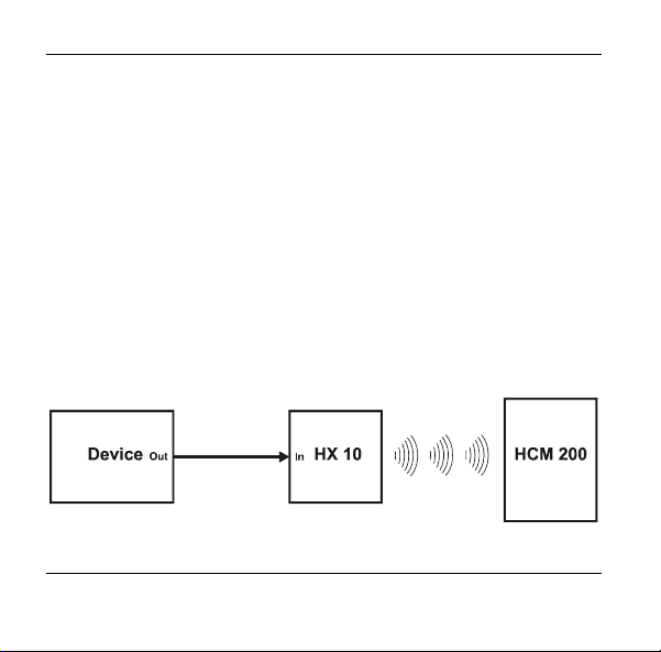
Application
The HX 10 extension module is a component of the home automation
system by Honeywell. It has 5 digital inputs (DI) and integrates digital
pickups (sensors, remote switches) as well as alarm systems using 2
different operating modes* (BA 1 and BA 2). Mode 1 allows 5 digital
inputs to be processed, mode 2 communication with ADEMCO alarm
systems (Lynxr) via the X-10 interface*. All other alarm systems that
have one of the connection options illustrated on Page 16, are
controlled using mode 1. The required mode is set using DIP
switches.
2
Page 7
Overview
The status* of a digital input is displayed in HCM 200 by YES-NO
pairs. Each change in the status of a digital input can be assigned a
relevant lifestyle in the HCM 200 Hometronic Manager.
The extension module is intended for surface mounting and can be
supplied with 12 VAC / VDC with the HN 10 power supply unit or
externally.
Modes
From the point of view of HCM 200, mode 1 for processing 5 digital
inputs and mode 2 for the integration of the ADEMCO alarm system
behave identically. The digital inputs 1 - 5 correspond to the device
addresses A1 - A5 of the X-10 protocol, that is, the first sensor input
corresponds to A1, the second sensor input corresponds to A2 etc.
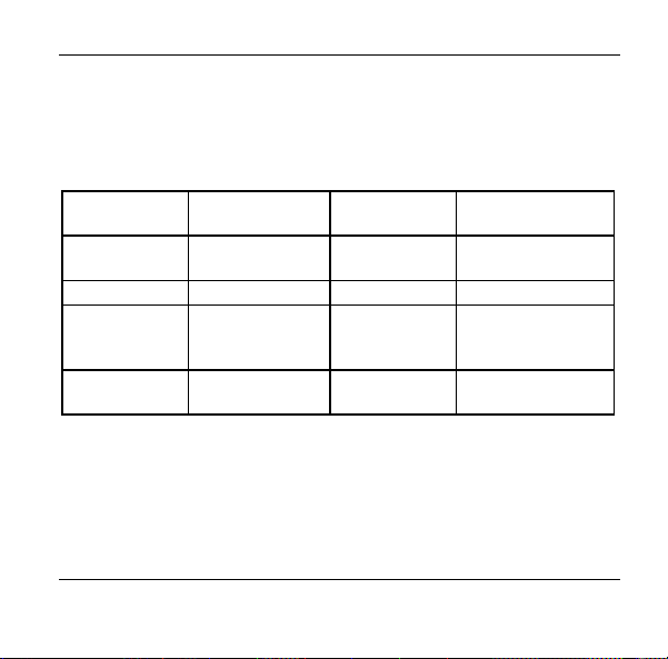
Address assignment
BA 1 (DI) BA 2 (X-10)
1
2
3
4
5
Home code*: A
Key code: 1
Home code: A
Key code: 2
Home code: A
Key code: 3
Home code: A
Key code: 4
Home code: A
Key code: 5
3
Page 8
Overview
In BA 2, it must be guaranteed during the programming of the
alarm system that home code A is used for triggering the
alarm.
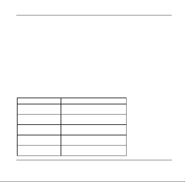
Status* assignment
The correspondence between the status at the digital inputs and the
X-10 protocol is as follows:
Voltage DI DI X-10 command*
0 Low (0) OFF
12 VAC / VDC High (1) ON
When mode BA 2 is set, all digital inputs are switched off.
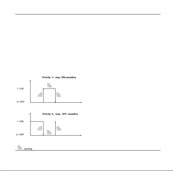
Setting Mode and Priority*
Setting the mode comprises deciding in favour of mode 1 or 2 and the
general setting of the priority for the digital input DI1 or the device
address A1.
Priority can only be defined for DI1 or A1.
By assigning priority, alarms can be treated preferentially in BA 1 as
well as in BA 2.
4
Page 9
Overview
If DI1 or device address A1 is set to priority, the status of the DI1 is
transmitted cyclically (2 min ± 30 sec) to the HCM 200 until the cause
of the alarm is eliminated. In HCM 200, the lifestyle triggered by the
alarm is constantly reactivated.
As long as the alarm is active, actions in HCM 200, e.g. the manual
triggering of a lifestyle, are cyclically overwritten. The priority of the
DI1 can be 0 or OFF or 1 or ON-sensitive. This means that at 0 (OFF)
sensitivity*, a signal is only sent cyclically when 0 (OFF) is active at
DI1 (A1), at 1 (ON) sensitivity, a signal is only sent cyclically when 1
(ON) is active at DI1 (A1).
5
Page 10
Overview
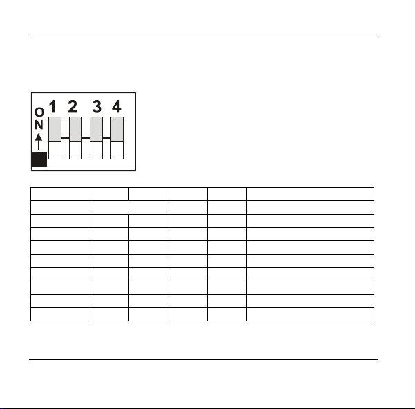
If DI1 is not set to priority, the status of an input is sent to HCM 200 as
a default after each status change*. The priority and mode are set
using 4 DIP switches as follows:
No. 1 2 3 4 Comment
Function
BA 1
Priority BA -
OFF OFF 0FF OFF
No priority set
1
ON OFF 0FF OFF 0 sensitive priority
OFF ON 0FF OFF 1 sensitive priority
BA 2
OFF OFF ON OFF No priority set
ON OFF ON OFF OFF sensitive priority
OFF ON ON OFF ON sensitive priority
1
All other DIP switch combinations behave like OFF OFF OFF OFF.
6
Page 11
Overview
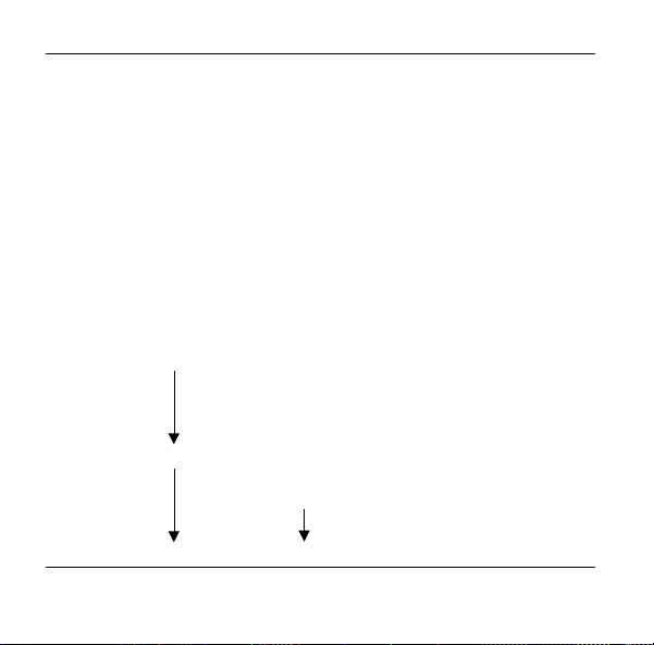
Communication with HCM 200
The HX 10 extension module transmits without time delay as soon as
a digital input status changes or an X-10 command* has been
received. The ADEMCO alarm systems transmits X-10 commands
which, as the following table shows, correspond to the status changes
in mode 1 and are treated identically from the point of view of HCM
200, that is, whether a DI changes from 0->1 or a device address from
OFF->ON, this causes the same message to be transmitted and thus
activates the assigned lifestyle. The status is shown in HCM 200 as
YES-NO pairs.
BA 1
Digital
inputs
DI 1: 1 -> 0 A1 = ON -> OFF NO
DI 1: 0 -> 1 A1 = ON -> OFF YES
DI 2: 1 -> 0 A2 = ON -> OFF NO
DI 2: 0 -> 1 A2 = OFF-> ON YES
DI 3: 1 -> 0 A3 = ON -> OFF NO
DI 3: 0 -> 1 A3 = OFF-> ON YES
DI 4: 1 -> 0 A4 = ON -> OFF NO
DI 4: 0 -> 1 A4 = OFF-> ON YES
DI 5: 1 -> 0 A5 = ON -> OFF NO
DI 5: 0 -> 1 A5 = OFF-> ON YES
BA 2
X-10 interface
Device address + data
HCM 200
Status
display
Flank for
lifestyle
activation
↓
↑
↓
↑
↓
↑
↓
↑
↓
↑
7
Page 12
Overview
Teach-in (installation) and current status display
The digital inputs are installed as sensors in HCM 200. During
installation, each extension module always occupies 5 sensor slots. In
this context please note the maximum number of sensors that can be
installed. If less than 5 sensors are wired, we recommend that the
excess sensors should be de-installed.
Example:
Installation of 2 HX 10 modules (1 + 2) with 1 x 5 or 1 x 3 sensors with
3 sensors already installed (slots 1-3).
Sensor slot Installation De-installation Installed sensors
Outside temp ...
Bright ....
Wind .....
Sensor 4 HX 10 (1) Sensor 4
Sensor 5 Sensor 5
Sensor 6 5 sensors Sensor 6
Sensor 7 Sensor 7
Sensor 8 Sensor 8
Sensor 9 HX 10 (2) Sensor 9
Sensor 10 Sensor 10
Sensor 11 5 sensors Sensor 11
Sensor 12 2 sensors ......
Sensor 13 .....
8
Page 13
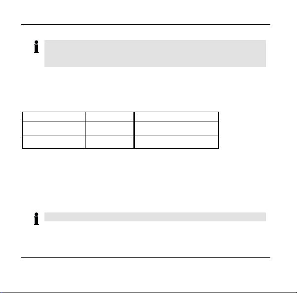
Overview
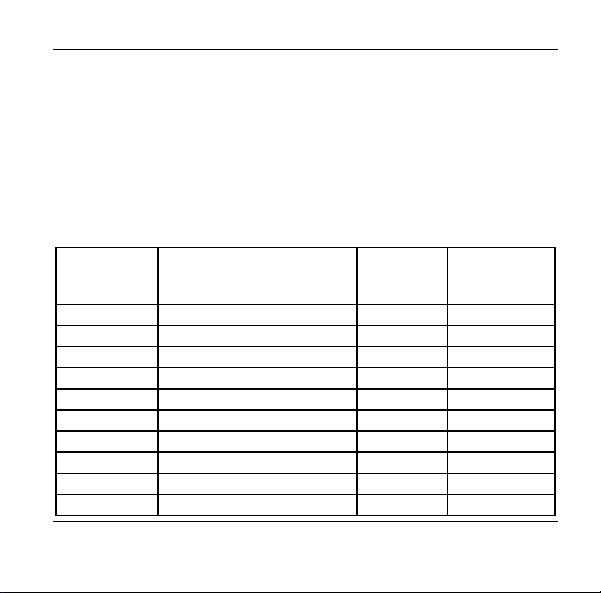
The sensor name can be edited and the current status can be
followed in the "Display/Sensor Values" menu. The current status
(level) of a DI is displayed with the value "YES" or "NO". The
assignment of the display to the level at the digital input or to the X-10
command is as follows:
HCM 200
display
YES
NO 0 V or open OFF in operation
- - undeterminedduring startup in
! No sensor signal
After the installation of an extension module the HCM 200 shows the
current status directly at the digital inputs in mode 1 only. In mode 2
all inputs are set to "--" during startup and during a new teach-in, since
no X-10 commands have been received yet.
Level at DI X-10
12 VDC or 12
VAC
command
ON in operation
Comment
BA 2 and during
a new teach-in
received for 3 h
9
Page 14

Overview
Since the sensor name can be edited, the following displays, for
example, can be shown during operation in HCM 200 in the
"Display/Sensor Values" menu:
Alarm: YES
Roof window closed ? NO
Valve closed ? YES
This means that you can rename the sensor names in the form of a
question or statement that is answered using YES or NO depending
on the current level at DI.
Assigning Lifestyles (HCM 200)
Each status change can be assigned a relevant lifestyle in HCM 200.
As well as the 16 lifestyles that have been programmed so far, 2
further lifestyles have been defined, lifestyles 0 and 17. If lifestyle 0 is
assigned, nothing changes when it is activated. If lifestyle 17 is
assigned, automatic mode* is started when it is activated and the
switching status active in the time program is set. One and the same
lifestyle can be used by several extension modules.
The default setting for the assignment of input status to lifestyle
number is "0".
10
Page 15
Overview
Please note, that an assigned lifestyle will only be displayed
and carried out in the HCM 200 if at minimum one action, e.g.
"Switch On Light" had been programmed for the lifestyle.
Lifestyles are assigned in the "Settings/Expansion Modules" menu.
11
Page 16

How to proceed during installation
How to proceed during installation
Preparation
Install Hometronic components such as for example HA 30, HS 30,
HAC 30 etc. and assign to a lifestyle as a module (see mounting
instructions for Hometronic components and HCM 200 operating
instructions, section "Assigning a module or a room to a lifestyle").
Mounting
• Mount the HX 10 (provisionally)
• Connect devices to the HX 10
• Set mode using DIP switches
Teach-in (installing sensors)
• Activate teach-in in HCM 200
• Continue teach-in at the HX 10
De-installing sensors (optional)
If fewer than 5 physical sensors have been installed, the excess
sensors should be removed in the HCM 200.
12
Page 17

How to proceed during installation
Assigning lifestyles (optional)
In the HCM 200 a D1 or a device address can be assigned a lifestyle
which is triggered in the event of a status change.
Checking digital inputs /X-10 commands
Allows a function check of the digital inputs for correct wiring.
Transmitting the status of the digital inputs
The current status of the digital inputs can be transmitted to the HCM
200 by pressing a pushbutton on the HX 10.
Final mounting
After the function check, complete mounting of the HX 10.
13
Page 18

Mounting
Mounting
The extension module has a radio transmitter whose
correct functioning can be adversely affected by
Attention!
Routing cables
The extension module is designed for surface mounting on the
HMF01 mounting base which is also supplied. The HMF01 mounting
base can be mounted for horizontal or vertical cable routing.
When using several extension modules, the HMF01 mounting base
can be cascaded. In this case, use the enclosed spacer. The following
description applies for the mounting of an extension module using a
mounting base. When mounting several modules, take account of the
additional cable lengths.
14
metallic objects and radio units.
► When selecting the operation location make sure
there is sufficient distance from metallic objects such
as metal cabinets and doors, concrete ceilings with
iron reinforcement and radio units such as radiocontrolled headphones etc.
Page 19

► Open the cable inlets on the
HMF01 mounting base using
a screwdriver.
► Screw the mounting base to
the wall in accordance with
the drilling template, in this
case for horizontal cable
routing.
► Insert the cable.
► Remove the housing cover of
the extension module.
Mounting
65
60
15
Page 20

Mounting
► Open the contact covers using
a screwdriver.
► Run all of the cables through the openings in the base of the
housing.
Connect devices to the HX 10
Sensors, outputs of alarm systems as well as remote switches can be
connected to the extension module. The following diagrams show the
basic connection options for the two modes.
16
Page 21

0 V / 12 V Output
Mounting
17
Page 22

Mounting
Open Collector Output
18
Page 23

Switch
Mounting
19
Page 24

Mounting
Alarm System
20
Page 25

Mounting
The following diagram shows the terminal assignment for connecting
devices for the two modes.
► Connect the sensors and the
supply voltage to the terminal
blocks in accordance with the
diagram and table.
L
1
2
3
R
4
1
2
3
4
21
Page 26

Mounting
Terminal block L
No. 1 2 3 4
BA 1 V in Gnd Inp1 Inp2
Supply voltage
12 VAC / 12 VDC
BA 2 V in Gnd Data* Sync*
Supply voltage
12 VAC / 12 VDC
No. 1 2 3 4
BA 1 Inp3 Inp4 Inp5 V in
dig. input
DI 3
12 VAC /
12 VDC
BA 2NCNCNCNC
not assigned not assigned not assigned not assigned
► First attach the base of the housing provisionally to the mounting
Earth dig. input
DI 1
12 VAC /
12 VDC
Earth Data (13) Sync (14)
Terminal block R
dig. input
DI 4
12 VAC /
12 VDC
dig. input
DI 5
12 VAC /
12 VDC
dig. input DI
2
12 VAC /
12 VDC
Supply
voltage
12 VAC /
12 VDC
base in order to be able to carry out adjustments if required.
22
Page 27

Mounting
Setting the mode
► Set the required mode using the DIP switches on the board of the
housing cover (see Page 4).
► Push the housing cover – making sure the pins fit in the terminal
blocks – onto the base of the housing.
23
Page 28

Teach-In*
Teach-In*
New Hometronic components must be assigned to the Hometronic
Manager before they can be put into operation. This procedure is
called "Teach-In".
Activate Teach-in in Hometronic Manager
Make sure that the Hometronic Manager is in automatic mode (the
yellow LED
Switch to the "Installation" submenu
► The display shows the standard
screen, e.g:
► Press Enter button on the Hometronic
Manager.
The following appears on the
display:
► Turn Enter button to the right to move
the cursor to the top line.
The following appears on the
display:
24
on the Hometronic Manager lights up).
Hometronic
WE 29.10.1999 11:15
No Lifestyle active
LIVING 20.0 C
MENU
SET DATE/TIME
ACTIVATE LIFESTYLE
LIVING 20.0 C
MENU
SET DATE/TIME
ACTIVATE LIFESTYLE
LIVING 20.0 C
Page 29

► Press Enter button.
The following appears on the
display:
► Turn Enter button to the left until the
menu item "Settings" is highlighted.
The following appears on the
display:
► Press Enter button twice.
The following appears on the
display:
The "Installation" submenu is selected.
► Turn Enter button to the left until the
menu item "Sensor" is highlighted.
The following appears on the
display:
► Press Enter button
The following appears on the
display:
In this case, sensors 1- 4(5) are
free.
Teach-In*
LIFESTYLES
TIME PROGRAMS
DISPLAY
SETTINGS
LIFESTYLES
TIME PROGRAMS
DISPLAY
SETTINGS
HEATING
SHUTTERS
DEVICES/LIGHT
SENSOR
HEATING
SHUTTERS
DEVICES/LIGHT
SENSOR
SENSOR-1
SENSOR-2
SENSOR-3
SENSOR-4
25
Page 30

Teach-In*
If possible, select from the list the free sensor that
subsequently allows the installation of 5 sensors. If there are
not 5 successive free slots available, the next free slots are
occupied. If there are no more slots, the excess sensors are
not installed.
► Press Enter button.
The cursor flashes on the right of the
highlighted line.
SENSOR-1 C
SENSOR-2
SENSOR-3
SENSOR-4
Continue Teach-in at the HX 10 extension module
► Press pushbutton on the extension
module for at least 5 seconds.
The green LED integrated in the
pushbutton lights up and goes off
briefly after 5 seconds.
In the HCM 200 display, a * appears
briefly for each sensor and then the
message DIGITAL. A total of 5
sensors are installed.
SENSOR-1 DIGITAL
SENSOR-2 DIGITAL
SENSOR-3 DIGITAL
SENSOR-4 DIGITAL
If you have wired less than 5 sensors, you are recommended
to de-install the excess sensors (see section De-installing
Sensors, Page 28)
26
Page 31

Successful Teach-In
–
–
If the teach-in was successful, the following status is shown for 5
sensors in the installation menu of the HCM 200, as described above:
SENSOR-1 DIGITAL
SENSOR-2 DIGITAL
SENSOR-3 DIGITAL
SENSOR-4 DIGITAL
Unsuccessful Teach-In
If a *, or nothing, is displayed for a sensor, the teach-in was
unsuccessful.
► Improve transmission, prevent faults or screening, for
example through:
cordless headphones, garage door openers, remote
control units, metal parts
If possible, change the position of the extension
module.
► Repeat the teach-in (see Page 24 onwards).
Teach-In*
27
Page 32

De-installing sensors
De-installing sensors
During the teach-in, the default setting is that 5 sensors are installed
for one extension module. If you have wired less than 5 sensors, you
are recommended to de-install the excess sensors in order to be able
to assign the sensor slots otherwise.
Switch to the "De-Installation" submenu
► The display shows the standard
screen, e.g:
► Press Enter button on the Hometronic
Manager.
The following appears on the
display:
► Turn Enter button to the right to move
the cursor to the top line.
The following appears on the
display:
► Press Enter button.
The following appears on the
display:
28
Hometronic
WE 29.10.1999 11:15
No Lifestyle active
LIVING 20.0 C
MENU
SET DATE/TIME
ACTIVATE LIFESTYLE
LIVING 20.0 C
MENU
SET DATE/TIME
ACTIVATE LIFESTYLE
LIVING 20.0 C
LIFESTYLES
TIME PROGRAMS
DISPLAY
SETTINGS
Page 33

► Turn Enter button to the left until the
menu item "Settings" is highlighted.
The following appears on the
display:
► Press Enter button.
The following appears on the
display:
► Turn Enter button to the left until the
menu item "DE-INSTALLATION" is
highlighted.
The following appears on the
display:
► Press Enter button.
The following appears on the
display:
► Turn Enter button to the left until the
menu item "SENSOR" is highlighted.
The following appears on the
display:
De-installing sensors
LIFESTYLES
TIME PROGRAMS
DISPLAY
SETTINGS
INSTALLATION
DE-INSTALLATION
FUNCTION EXPANSION
SENSOR FUNCTION
INSTALLATION
DE-INSTALLATION
FUNCTION EXPANSION
SENSOR FUNCTION
HEATING
SHUTTERS
DEVICES/LIGHT
SENSOR
HEATING
SHUTTERS
DEVICES/LIGHT
SENSOR
29
Page 34

De-installing sensors
► Press Enter button.
The following appears on the
display:
► Turn Enter button to the right or the
left in order to highlight the sensor to
be de-installed, in this case sensor 3.
The following appears on the
SENSOR-1 DIGITAL
SENSOR-2 DIGITAL
SENSOR-3 DIGITAL
SENSOR-4 DIGITAL
SENSOR-1 DIGITAL
SENSOR-2 DIGITAL
SENSOR-3 DIGITAL
SENSOR-4 DIGITAL
display:
► Press Enter button.
The following appears on the
display:
SENSOR-1 DIGITAL
SENSOR-2 DIGITAL
SENSOR-4 DIGITAL
SENSOR-5 DIGITAL
The sensor in question, in this case sensor 3, is now de-installed.
30
Page 35

Assigning lifestyles
Assigning lifestyles
In HCM 200, each DI and each device address A1 .. A5 can be
assigned a suitable lifestyle which is triggered as soon as a status
change has taken place at this input. Lifestyles are assigned to a
sensor as a number. In the "Lifestyles" submenu, you should therefore
note the position of the lifestyle you would like to assign.
Switch to the "Expansion Modules" submenu
► The display shows the standard
screen, e.g:
► Press Enter button on the Hometronic
Manager.
The following appears on the
display:
► Turn Enter button to the right to move
the cursor to the top line.
The following appears on the
display:
Hometronic
WE 29.10.1999 11:15
No Lifestyle active
LIVING 20.0 C
MENU
SET DATE/TIME
ACTIVATE LIFESTYLE
LIVING 20.0 C
MENU
SET DATE/TIME
ACTIVATE LIFESTYLE
LIVING 20.0 C
31
Page 36

Assigning lifestyles
► Press Enter button.
The following appears on the
display:
► Turn Enter button to the left until the
menu item "Settings" is highlighted.
The following appears on the
display:
► Press Enter button.
The following appears on the
display:
► Turn Enter button to the left until the
menu item "EXPANSION
MODULES" is highlighted.
The following appears on the
display:
► Press Enter button.
The following appears on the
display:
32
LIFESTYLES
TIME PROGRAMS
DISPLAY
SETTINGS
LIFESTYLES
TIME PROGRAMS
DISPLAY
SETTINGS
INSTALLATION
DE-INSTALLATION
FUNCTION EXPANSION
SENSOR FUNCTION
CHANGE NAMES
CONFIGURATION
LOCAL OPERATION LOCK
EXTENSION MODULES
Assign Lifestyle:
SENSOR-1 ↓ LS 0
SENSOR-1 ↑ LS 0
SENSOR-2 ↓ LS 0
Page 37

Assigning lifestyles
For each sensor, an individual lifestyle can be assigned for a
falling ↓ flank as well as for a rising ↑ flank of the status
change. Here, please note the physical wiring of the digital
input and/or the X-10 command.
► Turn Enter button to the left or to the
right in order to highlight the required
sensor with the appropriate flank
change.
The following appears on the
display, for example:
► Press Enter button.
The following appears on the
display:
► Turn Enter button to the right and set
the required lifestyle number. Press
the Enter button.
The following appears on the
display, for example:
The sensor was assigned lifestyle 5, which is triggered on a rising
flank.
Assign Lifestyle:
SENSOR-1 ↓ LS 0
SENSOR-1 ↑ LS 0
SENSOR-2 ↓ LS 0
Assign Lifestyle:
SENSOR-1 ↓ LS 0
SENSOR-1 ↑ LS 0
SENSOR-2 ↓ LS 0
Assign Lifestyle:
SENSOR-1 ↓ LS 0
SENSOR-1 ↑ LS 5
SENSOR-2 ↓ LS 0
33
Page 38

Assigning lifestyles
34
Page 39

Checking digital inputs /X-10 commands
Checking digital inputs /X-10 commands
After a successful teach-in, the HX 10 extension module allows a
function check of the physical inputs for correct wiring and/or
transmission of X-10 commands (test mode).
► In the HCM 200, switch to the "Display/Sensor Values" menu.
► Push the housing cover onto the HX 10.
► Press the pushbutton on the HX 10 for at least 10 seconds.
The green LED integrated in the pushbutton lights up as follows.
After 10 seconds, the extension module is in test mode.
35
Page 40

Checking digital inputs /X-10 commands
The function check can now be carried out for a maximum of
10 minutes.
► Trigger a status change at the relevant digital input or through the
alarm system at the relevant device address.
If the status changes at the DI or at the device address A, the
green LED on the extension module lights up briefly to show that a
status change has been transmitted to the HCM 200. In the HCM
200, the status change for the sensors can be followed in the
"Display/Sensor Values" menu by means of a YES-NO switch.
In this context please also note the assignment of the
lifestyles to the corresponding inputs (see Page 30)
36
Page 41

Transmitting the status of the digital inputs
Transmitting the status of the digital inputs
The current status of the digital inputs can be transmitted at the press
of a button.
► Press the pushbutton on the HX 10 for approx. 2 seconds until the
green LED integrated in the pushbutton lights up.
The status information has been transmitted.
37
Page 42

Final mounting
Final mounting
► After the function check of the inputs, remove the housing cover
again.
► Clamp the contact covers in
the base of the housing.
► Screw the base of the
housing onto the HMF01
mounting base in
accordance with drilling
template.
For horizontal cable
routing, 2 holes are
available, for vertical
cable routing 4 holes.
38
Page 43

► Push the housing cover -
making sure the pins fit in the
terminal blocks – onto the
base of the housing.
► Make sure that the housing
cover snaps into place.
Mounting is completed.
Final mounting
39
Page 44

Glossary
Glossary
Automatic mode
Standard operating mode of
the Hometronic Manager. All
the assigned areas are
controlled by means of time
programs.
Mode
One of two modes (BA 1,
BA 2) for the HX-10 which on
the one hand allows the
processing of signals from
wired pickups and on the other
hand also allows the X-10
protocol-supported
communication with alarm
systems.
Clk
See Sync.
Data
Port for data transmission of
the X-10 interface.
40
Home code
Specified code for alarm
systems that communicate via
the power network.
Manual mode
No time program active,
actuation of the setpoint value
by means of selecting wheel.
Priority
Setting of the digital input DI1 or
the device address A1. By
assigning priority, alarm
messages can be treated
preferentially in BA 1 as well as
in BA 2. The triggering alarm is
not interrupted by the activation
of other lifestyles.
Sensitivity
Logical status of the DI1 and of
the A1 device address when
priority has been assigned:
Page 45

0 sensitive = 0 V=OFF,or 1
sensitive 1=12 V=ON.
Stati
See Status.
Status
State (0 or 1) of a digital input.
Status change
Change in state at a digital
input from 0→1 or 1→0.
Change of a device address
from OFF→ON or ON→OFF.
Sync
Port for synchronising data
transmission of the X-10
interface.
Teach-in
The process of assigning a
model to the Hometronic
Manager.
Glossary
X-10 command
Transmitted command, ON or
OFF of the alarm system in
accordance with X-10 protocol.
X-10 interface
Interface to ADEMCO Alarm
systems (Lynxr).
41
Page 46

Technical Data
Technical Data
Operating voltage 12 VAC / VDC ± 20 %
Max. power consumption 40 mA (AC), 20 mA (DC)
Voltage DI 12 VAC / VDC ± 20 %
Max. pull-up resistance on DI
Operating temperature 0...40 °C
Protection class IP 20
Storage temperature –20 °C...+70 °C
Max. humidity 95 %, non-condensing
Digital inputs 5
Interface X-10
Min. transmission pause:
between 2 status changes
If lifestyle 17 was triggered
Power supply unit HN 10
Transmitter 433 MHz (< 1mW)
Max. cable length 30 m
42
100 kΩ (DC)
10 sec.
approx. 1 min.
Page 47

Help in the event of problems
Help in the event of problems
Problem/Display Cause Solution
Display of asterisk
"*" in the
"Installation" menu
of the HCM 200
Display of
exclamation mark "!"
in the main menu of
the HCM 200
Delayed execution
of a status change
Teach-in
unsuccessful
No supply voltage to
the HX 10.
Radio connection
disturbed for 3
hours.
Too frequent status
changes within the
transmission pause
of 10 sec.
Triggered lifestyle,
e.g. LS 17, includes
many actions
See "Improve
transmission" (Page 27).
Repeat teach-in
Establish supply voltage
(Page 16).
See "Improve
transmission" (Page 27).
Increase time interval
between 2 status
changes.
Increase time interval
between 2 events at HX
10 module
43
Page 48

Help in the event of problems
Problem/Display Cause Solution
"No lifestyle active"
message in HCM
200
No control by
Hometronic
Manager.
44
A lifestyle has not
been assigned a
module.
NOTE: This
message also
appears when an
input or a device
address is assigned
lifestyle 17
(standard message
in automatic mode).
Radio connection
faulty.
Assign module, see
"Assigning a lifestyle a
module or a room" in
HCM 200 operating
instructions.
See "Improve
transmission" (Page 27).
Page 49

Help in the event of problems
Notes for Installer
After mounting the extension module, you should inform your
customers about the Hometronic System:
► Familiarise your customers with the operation of Hometronic.
► Explain the manual operation of the components.
► Point out the special features and extension options of the customer
installation in question.
45
Page 50

Honeywell AG
Böblinger Straße 17
D – 71101 Schönaich
Telephone (+49) 7031 637-300
This company is certificated to
Ra di o f re que nc y r egi st rat io n: A, B, CH, D, DK, E, F, FIN, IT, LUX, N, NL, UK:
The right is reserved to make modifications. This document is definitive for the
enclosed product and replaces all previous publications.
Nr. 7157556 EN1H-0190 GE51 R0801
 Loading...