

Page 1
Wind Sensor
HWS 40
Mounting
Page 2

Page 3

Contents
Contents
Contents 1
Application 2
Mounting 3
Wiring 5
Changing the threshold value of the wind speed 7
Technical data 10
Help on any problems 11
1
Page 4
Application
Application
The wind sensor HWS 40 is part of the Hometronic System and
protects motor-driven awnings against damage through storms. A
vane anemometer measures the wind speed at the outer wall of the
building. The vane anemometer is hard-wired to the tube motor of the
awning and to the shutter module HA 30.
If the wind speed at the vane anemometer exceeds the set threshold
speed, the awning travels in immediately. The awning cannot be
traveled out again until the wind speed has not exceeded the
threshold value for a period of 16 minutes.
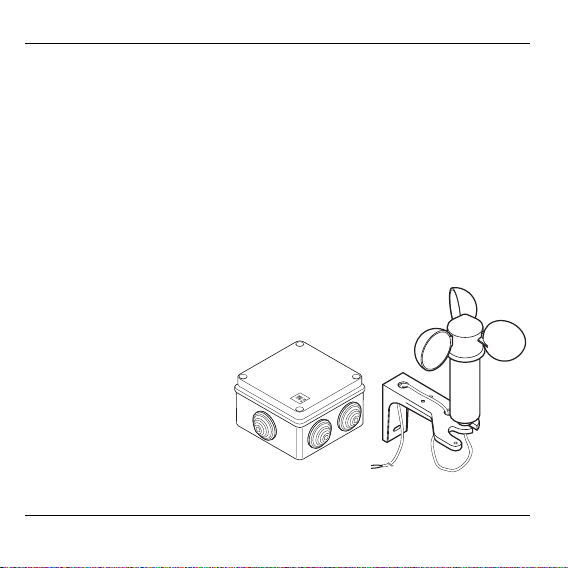
Scope of supply
Vane anemometer
Electronics box
Connecting cable
Fixing material
2
Page 5

Mounting
Mounting
Danger to life through electric shock!
Live electrical contacts lie open while the module is
Danger!
Selecting the mounting site
When selecting the mounting site for the vane anemometer and the
electronics box ensure that:
• The wind conditions at the cane anemometer correspond to those
at the assigned awning
• The electronics box is not subject to direct sun irradiation
• The supplied connecting cable may not be extended.
being cabled. Touching a live contact causes critical
injuries.
► All work may only be carried out by authorized
specialized personnel.
► De-energize the corresponding fuse during all work on
the module.
3
Page 6

Mounting
Overview
The following components are required for mounting:
A Vane anemometer
B Electronics box
C Motor-driven awning
D Shutter module HA 30
E Pushbutton for manual
operation
Connecting cable and fixing
material
► Select the mounting site for
every component.
► Mount the awning, push-
button and shutter module
HA 30 as described in the
respective operating
instructions.
4
Page 7

Wiring
Wiring
► Open the electronics box and fasten it at the mounting site.
Please refer to Page 10 for the dimensions.
► Fasten the vane anemometer at the mounting site.
► De-energizethe correspondingfuses.
Components are damaged if phases are interchanged
or if the local grounding specifications are not observed.
Caution!
► Wire the vane anemometer, electronics box, motor and shutter
module HA 30 in accordance with the wiring diagram on Page 6.
► Close the electronics box.
► Insert the fuse again.
► Ensure phase coincidence at the used components.
► Observe the local grounding specifications.
5
Page 8

Wiring
Wiring diagram
6
Page 9

Changing the threshold value of the wind speed
Changing the threshold value of the wind speed
The awning or shutter is damaged when the wind is
strong.
Caution!
► De-energize the corresponding fuse.
► Open the electronics box.
► Set the wind speed at which the awning is to travel in at the DIP
switches in the electronics box in accordance with the table on
Page 8.
► Close the electronics box.
► Insert the fuses again.
► The set threshold value should only be changed by
authorized specialized personnel.
7
Page 10

Changing the threshold value of the wind speed
Table of DIP switches
1234m/skm/h
OFF OFF OFF 3 10.8 2 Weak wind
OFF
OFF OFF OFF ON 5 18 3 Weak wind
OFF OFF ON OFF 6 21.6 4 Moderate wind
OFF OFF ON ON 7 25.2 4 Moderate wind
OFF ON OFF OFF 8 28.8 5 Fresh wind
OFF ON OFF ON 9 32.4 5 Fresh wind
OFF ON ON OFF 10 36 5 Fresh wind
OFFONONON11 39.66 Freshwind
ON OFF OFF OFF 12 43.2 6 Strong wind
ON OFF OFF ON 13 46.8 6 Strong wind
ON OFF ON OFF 14 50.4 7 Strong wind
ON OFF ON ON 15 54 7 Strong wind
ON ON OFF OFF 16 57.6 7 Strong wind
ON ON OFF ON 17 61.2 7 Strong wind
ON ON ON OFF 18 64.8 8 Storm
ON ON ON ON 20 72 8 Storm
The works setting of the wind speed amounts to 8 m/s.
8
Wind
force
Designation
Page 11

Changing the threshold value of the wind speed
Information for the fitter
After mounting and starting up has been completed, the Hometronic
System can be handed over to the customer.
► Familiarize your customer with the basic operation of the Hometronic
Manager.
► Explain the operation of the components on site.
► Also explain the possibilities offered by manual operation of the
components.
► If appropriate, point out the particular applications and possibilities
offered by extending the respective installation of the Hometronic
System.
9
Page 12

Technical data
Technical data
Operating voltage 230 V AC, 50 Hz
Operating temperature 0 to 50 °C
Intrinsic consumption Approx. 2 W
Switching capacity 230 V AC, 50 Hz, 5 A
Dimensions of the electronics box
105
15
20
105
20
12
15
10
Page 13

Help with problems
Problem Cause Remedy
The awning
cannot be
controlled
Awning does
not travel in at
high wind
speeds
Wind sensor
measures high
wind speeds
Cable break or
short-circuit
Faulty wiring
Cable break or
short-circuit
Threshold set
too high
► Wait until the strong wind drops
► If necessary, adapt the
threshold
► Check the cables for damage
► Check the wiring
► Check the cables for damage
► Adapt the threshold
Help with problems
11
Page 14

Honeywell AG
Böblinger Straße 17
D – 71101 Schönaich
Tel. (07031) 637-300
The right is reserved to make
modifications
This document is definitive for the enclosed product and replaces all previous
publications.
No. 7157549 EN1H-0150 GE51R0601
This company is certificated to
 Loading...