

Page 1
READ AND SAVE THESE INSTRUCTIONS
HE420A Steam Power Humidifier
INSTALLATION INSTRUCTIONS
APPLICATION
The HE420A Steam Power Humidifier uses a thermal fan
interlock control to provide humidification for the whole
house. The steam power humidifier is designed to work
with high efficiency furnaces and heat pumps.
INSTALLATION
IMPORTANT
This product is for residential applications only
and must be installed by a qualified HVAC contractor. Failure to comply could invalidate the
product warranty, or result in serious injury or
electrocution.
SELECT LOCATION AND MOUNT
WARNING
Electrocution, Heavy Equipment and
Chemical Hazard.
Can cause death, blindness, water damage to
home and heater failure.
• Do not cut into any air conditioning or
electrical line.
• Wear safety glasses when cutting or drilling.
• Mount the humidifier in a level position to
avoid water damage and heater failure.
• Reinforce duct as necessary to ensure
stability.
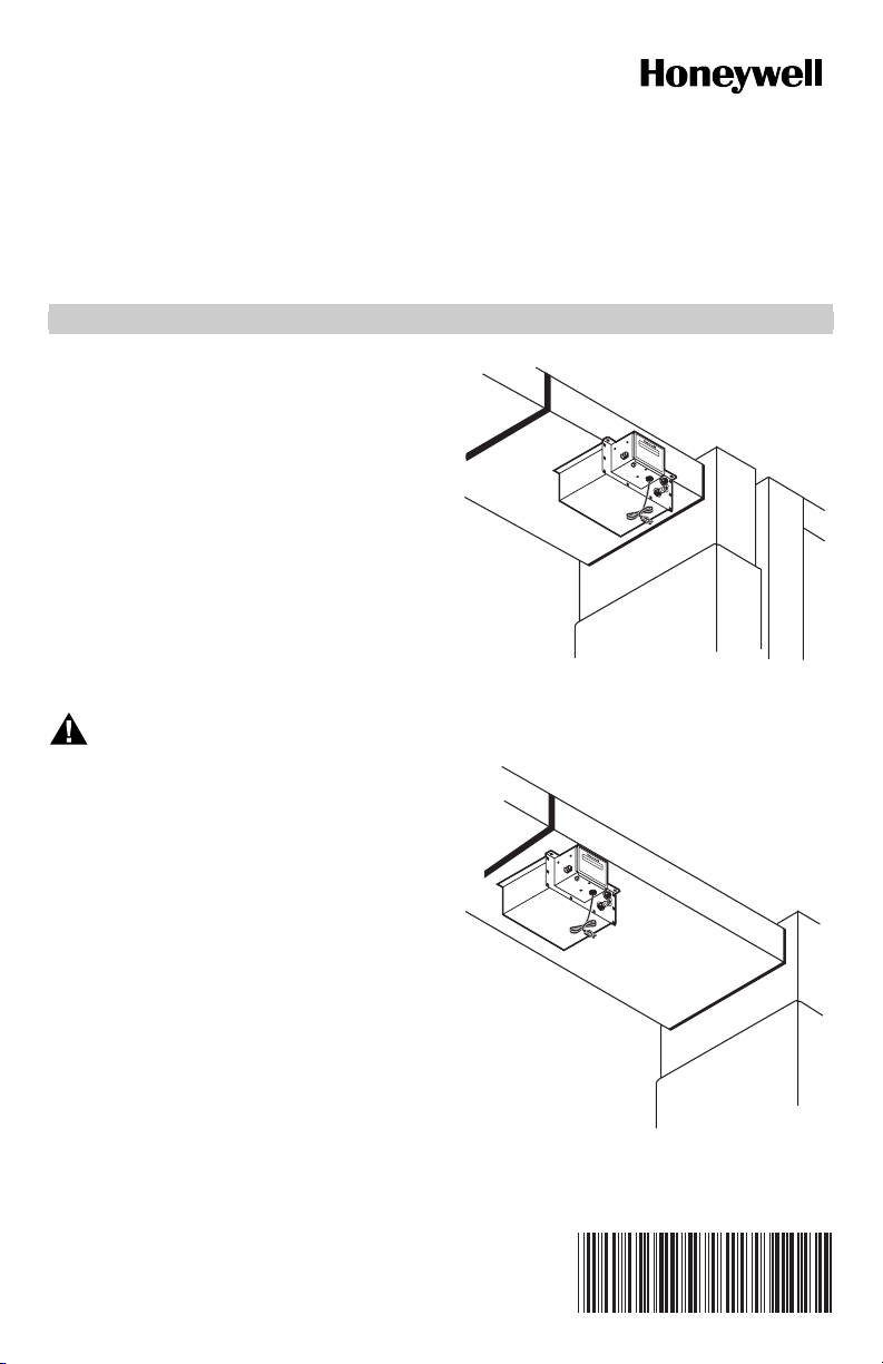
There are three typical ways of mounting the steam
humidifier. See Fig. 1, 2, and 3. Be sure to select a
location where the humidifier can be plugged in without
an extension cord. The preferred installation location is
on the warm air side of the furnace. If that location is not
possible, the humidifier should be mounted a minimum of
6 ft (1.8m) upstream from the furnace filter. Depending
on the location selected, additional duct reinforcement
may be necessary because the humidifier weighs 18 lb
when filled with water.
Fig. 1. Mount humidifier horizontally under duct
using mounting bracket.
HU
M
ID
H
IFIE
UM
R
ID
IFICATEU
R
H
UM
ID
H
IFIER
U
MIDIFICATEU
R
M10536B
M10578B
Fig. 2. Mount humidifier horizontally under duct.
69-1108-2
Page 2
HE420A STEAM POWER HUMIDIFIER
HUMIDIFIER
HUMIDIFICATEUR
Mount Horizontally Using Mounting Bracket (Preferred Mounting Method)
IMPORTANT
The duct must be at least 10 in. (254 mm) wide
to use this mounting method.
The duct is strongest when using the bracket mounting
method because the least amount of duct reinforcement
is required because of the bracket location. See Fig. 1.
However, in some installations, reinforcement may still be
necessary to help support the weight of the humidifier and
keep the humidifier level.
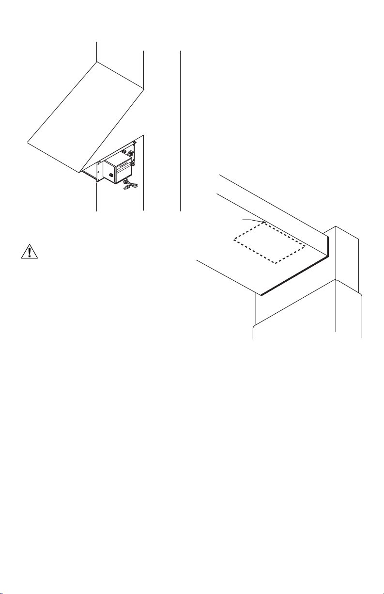
1.
Position the bracket 1/2 in. (13 mm) from the edge of
the duct and trace around the bracket. See Fig. 4.
2. Once the outline has been traced, remove bracket.
M10580B
Fig. 3. Mount humidifier horizontally under duct
extension using mounting bracket.
CAUTION
Steam Condensation, Fire and Freezing Water
Hazard.
Can cause failure of fan or limit control or
result in water damage to home.
• Do not install the humidifier where the
sidewalls of the return air duct are constructed
of wood (i.e. floor joist).
• Do not Install the humidifier where the
temperature is lower than 32°F (O°C) or higher
than 200°F (93°C).
• For all installation configurations, the mounting
area must be strong enough to support the
humidifier's weight when it is full of water
(approximately 18 lbs.), and to hold the
humidifier in a level position for safe, reliable
operation. Otherwise, additional duct
reinforcement will be necessary.
• If the installation includes exposed insulated
materials, a section of the ductwork must be
removed and replaced with rigid metal duct
extending at least 6 feet downstream from the
humidifier.
• Mount the unit at least 4-to-6 feet after the
plenum transition. Avoid sudden turns or
transitions in the ductwork in the immediate
area downstream from the humidifier.
There are three possible mounting procedures:
• horizontally under at least a 10 in. (254 mm) wide duct
using the mounting bracket (preferred mounting);
• horizontally under a reinforced duct;
• horizontally under a duct extension using the mounting
bracket.
Decide which mounting is appropriate and follow those
mounting instructions.
1/2 IN. (13 MM)
FROM EDGE
BRACKET
M23374
Fig. 4. Position bracket to duct edge.
3. Drill a 3/8 in. (10 mm) hole within the center portion
of the bracket.
4. Use tin snips to cut around the outline of the
bracket.
IMPORTANT
Follow the dotted line carefully.
5. Remove the sheet metal.
6. Use two 8-32 screws and nuts to attach the mount-
ing bracket (L shaped with six holes) to the top/front
surface of the humidifier. The humidifier is now
ready for mounting.
NOTE: Position the humidifier so the upward protrusion
of the U is on the side toward the reservoir.
IMPORTANT
Do not mount the humidifier until the water level
is adjusted. See the Plumbing section.
7. Slide the flanges of the humidifier reservoir into the
mounting bracket until the reservoir’s front flange
comes into contact with the edge of the duct.
8. Secure the humidifier to the duct with three no. 8
sheet metal screws.
69-1108—2 2
Page 3
HE420A STEAM POWER HUMIDIFIER
A
Mount Horizontally On Reinforced Duct
This horizontal mounting method usually requires duct
reinforcement to support the weight of the humidifier and
keep it level. The mounting bracket is not used. See Fig. 2.
1. Position the bracket to the bottom of the duct in the
desired location. Be sure the bracket is level.
2. Once the outline has been traced, remove bracket.
3. Drill a 3/8 in. (10 mm) hole within the center portion
of the bracket.
4. Use tin snips to cut around the outline of the
bracket.
5. Remove the sheet metal.
IMPORTANT
Do not mount the humidifier until the water level
is adjusted. See the Plumbing section.
6. Slide the flanges of the humidifier reservoir into the
mounting bracket.
7. Secure the humidifier to the duct with two no. 8
sheet metal screws.
Mount Horizontally On Vertical Duct
Horizontal mounting on a vertical duct requires the
installation of a duct extension. Additional duct
reinforcement may also be necessary to help support the
weight of the humidifier and keep it level. See Fig. 3.
Create and install the duct extension. Follow the steps in
the Mount Horizontally Using Mounting Bracket section to
complete installation.
WIRING
All wiring must comply with local codes and ordinances.
For complete wiring instructions, refer to the manual
“Wiring Instructions for High-Capacity Steam Humidifiers”
packaged with your HE420A humidifier.
PLUMBING THE HUMIDIFIER
CAUTION
Chemical Hazard.
Can cause damage to environment or air
conditioning system.
Do not use any refrigerant line connected to an air
conditioner.
Be sure to install the chlorine removal filter
(provided) to prevent humidifier corrosion.
NOTE: Either hard or soft water can be used in the
humidifier.
IMPORTANT
Use only copper tubing to plumb the humidifier.
1. Locate the cold water pipe closest to the humidifier.
2. Install the saddle valve connector.
3. Use the valve instructions to install the valve (pro-
vided). The valve is self-piercing when installed on
copper pipe.
IMPORTANT
Position the valve so water flows from the top or
side to reduce the chance of clogging the valve
with minerals.
Lightly clean the copper tubing ends with fine
sandpaper before making any connections.
Do not use any line connected to an air
conditioner.
4. Install the chlorine removal filter.
5. Place the brass compression nut over the copper
tubing.
6. Slide the brass ferrule over the tubing.
NOTE: Do not overtighten the compression nut.
Moderate tightness prevents leaking.
7. Insert the tubing into the valve fitting and tighten the
compression nut.
8. Flush the copper tubing to remove any debris that
can cause problems at the float valve.
9. Route the tubing to the humidifier float valve, keep-
ing the tube away from sharp edges.
10. Connect the remaining end of the tubing to the
humidifier float valve.
11. Open the saddle valve so that the water flows
slowly and gently into the water pan.
SET THE WATER LEVEL
CAUTION
Flooding Hazard.
Inadequate support of the float arm can lead to
valve seat damage resulting in water leakage.
Support the float arm during adjustment.
Adjust the humidifier water level prior to mounting.
1. Set the humidifier reservoir on a level surface.
2. Attach the water feed line and allow the unit to fill
until the float valve shuts off the incoming flow of
water. The water level should be between 2-1/4 in.
(57 mm) and 2-1/2 in. (64 mm) deep. If water level
is correct, skip to step 4.
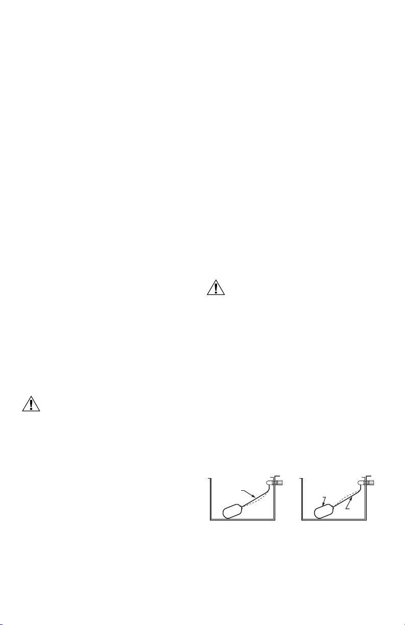
3. Adjust the water level in small increments. Raise
the water level by pushing down on the center of
the float arm. Lower the water level by pressing the
float down with one hand and pulling up on the center of the float arm with the other hand. See Fig. 5.
4. Verify the water level by removing enough water to
allow the float valve to automatically fill and shut off
the water.
TO RAISE WATER LEVEL
PUSH
DOWN
Fig. 5. Adjusting the water level.
TO LOWER WATER LEVEL
HOLD
DOWN
PUSH
UP
M10581
369-1108—2
Page 4

HE420A STEAM POWER HUMIDIFIER
FINISH MOUNTING AND PLUMBING THE HUMIDIFIER
1. Mount the humidifier as instructed in the Select
Location and Mount section.
2. Route the tubing to the humidifier float valve.
IMPORTANT
Keep the tubing away from sharp edges.
3. Connect the remaining end of the tubing to the
humidifier float valve.
4. Open the saddle valve so the water flows slowly
into the water pan.
5. Check the compression fittings at the saddle valve
and the float valve. Tighten the fitting slightly to stop
any leakage.
6. Connect the overflow provision of the humidifier to a
suitable waste drain.
NOTE: 3/8 in. (9.525 mm) I.D. tubing can be easily
attached to the overflow fitting.
7. Support the drain line at several locations to pre-
vent kinks. Be sure to provide support near any
heat source.
8. Use a male 1-1/2 in. NPT fitting (not supplied) to
connect the humidifier overflow provision.
INSTALL THE AUTOMATIC FLUSHING TIMER
Refer to the “Installation Instructions for the
Programmable Humidifier Automatic Flushing Timer” for
complete instruction.
INSTALL THE AUTOMATIC HUMIDISTAT CONTROL
For additional humidistat installation instruction, refer to
the manual “Wiring Instructions for High-Capacity Steam
Humidifiers.”
WARNING
Electrocution Hazard. Disconnect electrical
power to the furnace before beginning
installation.
Sharp edges. Use caution when cutting plenum
openings and handling ductwork
CAUTION
Do not mount the compensating humidistat on
the supply duct or plenum. The unit will not
withstand supply temperatures.
Do not set the humidity so high that condensation
forms on windows or walls.
SELECT LOCATION AND MOUNT
1. Check contents of the humidistat carton. Compo-
nents include:
• Automatic humidistat
• Outdoor temperature sensor
• Sensor shield
• Manual mode faceplate
• Mounting bracket
2. Disassemble the humidistat. Pull knob off, then
remove the cover by inserting a screwdriver in the
slot on the right side of the humidistat.
3. Mount the humidistat on the COLD AIR RETURN.
Select a mounting location at least 6 inches
upstream from the fresh air intake ductwork, if applicable.
4. Select an exterior location to mount the Outdoor
Temperature Sensor. Location must meet the following requirements. Incorrect indoor humidity levels will result if these requirements are not met.
• Mount on North, Northeast or Northwest side of
house.
• Mount at least 3 feet from all exhaust vents.
• Mount above expected snow line.
NOTE: For manual operation, do not install the outdoor
sensor wire.
5. Locate an existing Indoor/Outdoor access hole.
• Make sure there are no active high-voltage
wires in the hole.
• As an alternative, the sensor can be mounted in
the center of a 6-inch fresh air intake duct (must
be no farther than 30 inches from the outside
wall).
NOTE: If neither configuration is possible, the compen-
sating humidistat can be installed to operate
manually. See Installing the Humidistat to Operate Manually, below.
6. Route the sensor wire to the selected location. Run
wire between the compensating humidistat and the
outdoor sensor lead. If the sensor is outdoors, snap
the probe end of the sensor into the sensor shield
and attach it to an exterior wall. The probe must be
completely covered by the shield.
NOTE: Outdoor temperature sensor wire must not
exceed 30 feet in length.
CAUTION
Do not run outdoor temperature sensor wire
alongside wires carrying high voltage (120
VAC or higher). Do not run the sensor wire
through conduit.
7. Attach the Sensor Wire to the humidistat. Strip the
connecting wire 1/4 inch and attach the two internal
wires to the terminals labeled “Outdoor Temperature Sensor” on the humidistat.
8. Select a power source. The voltage to the humidis-
tat must be between 22-30 VAC.
NOTE: The compensating humidistat will operate prop-
erly only with a continuous power source. A minimum 10 volt amperes is required.
9. Connect the humidistat to the humidifier. Strip the
wires used for all the humidistat terminal connections 1/4 inch.
10. Set the humidistat. Consult the compensating humi-
distat homeowner's manual for proper humidity settings.
69-1108—2 4
Page 5

HE420A STEAM POWER HUMIDIFIER
Installing the Humidistat to Operate Manually
1. Locate the three-pin arrangement marked AUTO/
MAN protruding from the control board (right of wiring connections).
2. Pull upward to remove the black, two-pin connector
from the auto position. Reinstall it in the manual
position (on the center and right-hand pins).
CAUTION
Do not attach sensor wire to the blue wiring
connection block.
3. Follow Steps 8 (select a power source) and 9 (Con-
nect the humidistat to the humidifier) to complete
the wiring. Apply the manual mode faceplate to the
compensating humidistat cover. Reattach the cover
to the base and reinstall the knob.
HUMIDISTAT OPERATING INSTRUCTIONS
With automatic humidity control, you can control your
humidifier almost effortlessly, because:
• Once the knob has been set, the humidistat
automatically adjusts the indoor relative humidity
based on outdoor temperature and your desired
humidity level.
• The humidistat calculates the optimal humidity so you
don't have the problems associated with indoor
condensation.
• The humidistat’s temperature condensation capability
automatically turns itself on in cold weather, off in
warm weather.
• The humidistat’s humidity and temperature sensors
are solid-state, which means there are no mechanical
parts, and no problems associated with dust.
Automatic Operation
Once the humidistat is installed in the cold air return and
internally set to AUTOMATIC, turn the dial to 5 (the
standard humidity control setting).
Allow the humidity to stabilize for at least two days (home
size, furnace efficiency, and personal comfort preference
may affect the length of time necessary). At that point, you
may reset the dial to 6 for more humidity, or 4 for less
humidity. Continue adjusting the dial until you reach your
optimal indoor humidity level, and leave the dial in this
position.
Remember that in AUTO mode, the dial is not showing
relative humidity, but your preferred humidity setting
based on Table 1.
Table 1. Humidity Settings.
Dial
Position
1 10% 10% 10% 15% 20% 25%
2 10% 10% 15% 20% 25% 30%
3 10% 15% 20% 25% 30% 35%
Outdoor Temperature °F
-10 0 10 20 30 40
Table 1. Humidity Settings.
Dial
Position
4 15% 20% 25% 30% 35% 40%
5 20% 25% 30% 35% 40% 45%
6 25% 30% 35% 40% 45% 45%
7 30% 35% 40% 45% 45% 45%
Outdoor Temperature °F
-10 0 10 20 30 40
Manual Operation
For MANUAL operation, apply the manual mode decal to
the faceplate. Once the unit is installed in the cold air
return and internally set to MANUAL, turn the dial to the
expected outdoor temperature. The corresponding
optimal humidity level has been calibrated for you. For
example, by setting the dial to an anticipated 20°F, the
humidistat automatically maintains the indoor relative
humidity in the safe, comfortable 35% range (see Table 2
below).
Table 2. Recommended Relative Humidity.
Outside Temperature Recommended RH
+40°F 45%
+30°F 40%
+20°F 35%
+10°F 30%
0°F 25%
-10°F 20%
-20°F 15%
In extreme cold weather, relative humidity must be
reduced to prevent condensation on windows and interior
surfaces. Otherwise, the excess moisture will eventually
cause damage to your home.
Additional Features
• When outdoor temperature exceeds 50°F (10°C), the
humidistat will function in Test mode only.
• When indoor relative humidity exceeds 45%, the
humidistat will not operate.
• Test Mode—Manual test the humidistat by turning the
knob to the far right. The unit will energize the internal
relay for one minute, allowing you to confirm proper
operation.
• Manual Off—In Manual mode, turn the humidistat OFF
during warm months by turning the knob to the far left.
(This is not necessary in Automatic mode.)
HUMIDISTAT CHECKOUT
IMPORTANT
If conditions exceed 50°F or 45 percent relative
humidity, it may be necessary to perform this
test.
1. To conduct a system test, ensure that 24 VAC is
applied to the 24 VAC terminals of the compensating humidistat.
2. Reattach the humidistat cover and knob to the
base.
3. Rotate the knob on the humidistat clockwise to the
“Test” position.
569-1108—2
Page 6

HE420A STEAM POWER HUMIDIFIER
a. If set up correctly, the humidifier will begin oper-
ating. In “Test” mode, the humidistat will operate
for approximately one minute.
b. If the humidifier does not activate properly in
“Test” mode, refer to Appendix A.
4.
Set the humidistat. Refer to Humidistat Operating
Instructions for detailed instruction on initial settings.
a. If home is occupied, set the knob to “5”, or for
manual operation, set the knob to 35%.
b. If home is vacant, turn the knob to counterclock-
wise to “Off.”
INSTALL THE SAFETY CONTROL SHUTOFF
Refer to the manual “Wiring Instructions for High-Capacity
Steam Humidifiers” (page 11) for complete instruction on
installing the Safety Control Shutoff.
CHECK THE HUMIDIFIER OPERATION
After installation is complete, use the following steps to
check the humidifier operation:
1. Turn on the humidifier water supply.
2. Be sure the humidifier has power and then plug in
the humidifier.
3. Turn the Humidity Control to the Test position.
NOTE: If relative humidity is above 45% in the home, or
the outdoor temperature is above 50°F, a jumper
may need to be placed across the humidistat’s
OUT terminals to perform this checkout.
4. Check that the furnace blower comes on to circulate
the moist air. The blower may take as long as fifteen
minutes to start.
5. Refer to the Humidity Control owner’s manual for
operation.
69-1108—2 6
Page 7

HE420A STEAM POWER HUMIDIFIER
APPENDIX A
Table 3. Compensating Humidistat Troubleshooting Guide.
PROBLEM SOLUTION NOTES
Humidifier does not
operate in “Test”
mode.
Humidifier only
operates in “Test”
mode.
Humidifier operates
constantly.
Humidifier or
compensating
humidistat “chatters”
or clicks on and off
rapidly.
Furnace or heat
pump blower system
runs continuously;
condensation is
building up in
ductwork.
• Confirm the outdoor temperature sensor is
connected to the correct terminals on the
humidistat. (For manual operation, ensure the
jumper pins are positioned correctly.)
• Check wiring diagram (Figure 1) for correct
installation.
• Check the voltage at the humidistat “24 VAC”
terminals. (Should be 22-30 VAC.)
• Ensure the control knob has not been left in the
“Test” position.
• Check the resistance of the sensor by removing
the leads from the humidistat terminals and
measuring the resistance across the wires with
an ohmmeter. Compare the reading to the
temperature/resistance chart (right).
• For automatic applications, make sure the
outdoor temperature sensor is mounted
completely outside the house (i.e. not recessed
into the hole) on the North, Northeast or
Northwest side, away from direct sunlight. And is
mounted at least 3 feet away from all exhaust
vents.
• If the outdoor temperature sensor is mounted in
the fresh air intake duct, make sure the probe is
no further than 30 inches from an outside wall.
• Check the humidistat setting. If the RH in the
home is less than the knob setting, the humidifier
will operate until the humidity level is higher than
the knob setting.
• In “Test” mode, verify that the humidifier will shut
off after approximately one minute.
• Check the resistance of the sensor.
• See previous Problem/Solution, regarding
outdoor temperature sensor mounting locations.
• Turn the humidistat “OFF” and observe whether
the humidifier turns off. If operation continues,
check Figure 1 wiring diagram. Remove the
wires from the humidistat's “OUT” terminals. If
humidifier continues to operate, check the
humidifier.
• Use a voltmeter to check for steady 22-30 VAC.
• Make sure the outdoor temperature sensor
wiring does not run alongside the wires carrying
high voltage (120 VAC or higher).
• It may be necessary to make a setting change on
the furnace or heat pump board to prevent the
blower from shifting down to lowest idling speed.
• Consult the furnace/heat pump operating manual
or contact the manufacturer for procedures to
prevent low air flow.
Temp/Resistance Chart
100°F 6000 ohms 38°C
90°F 7500 ohms 32°C
80°F 9500 ohms 27°C
70°F 11,500 ohms 21°C
60°F 14,000 ohms 16°C
50°F 18,000 ohms 10°C
40°F 23,000 ohms 4°C
30°F 28,500 ohms -1°C
20°F 37,000 ohms -7°C
10°F 46,500 ohms -12°C
0°F 61,500 ohms -18°C
-10°F 78,500 ohms -23°C
-20°F 105,500 ohms -29°C
-30°F 135,000 ohms -34°C
Notes:
In automatic applications, if the outdoor
temperature is greater than +50°F (+10°C)
or less than -32°F (-35.6°C), the
compensating humidistat will not operate
(except in “Test” mode).
In both automatic and manual applications,
if the relative humidity in the home is
higher than the knob setting, the
humidistat will not operate. Similarly, the
humidistat will not operate if the indoor RH
exceeds 45%.
769-1108—2
Page 8

HE420A STEAM POWER HUMIDIFIER
APPENDIX B
Table 4. Safety Control Relay (SCR) Operation and Troubleshooting Guide.
Condition Cause Action Required
SCR LED shows rapid series of red,
green, and yellow lights, followed by
no LED display.
Humidifier won't operate. No SCR
LED display.
Humidifier operates. SCR LED shows
continuous yellow.
Humidifier won't operate. SCR LED
shows continuous red.
Humidifier operates. SCR LED shows
continuous green.
Humidifier won't operate. SCR LED
shows flashing red.
* Before the SCR can be reset, the system must be checked and repaired by a licensed contractor. To reset the SCR,
insert a rigid, small-diameter object (e.g. paperclip) into the smallest hole in the face of the SCR, next to the green
connector block. This, too, should be performed by an HVAC contractor.
Condition Normal. SCR processor is
powering up and checking internal
operation.
Problem! SCR circuit is not closing or
humidistat is not calling for humidity.
Condition Normal. This is a test phase.
SCR will wait 30 minutes to detect
furnace blower operation. If the
furnace blower is detected, the system
will function properly.
Problem! During the 30 minute test
phase, the SCR failed to detect the
furnace blower and turned the
humidifier off.
Condition Normal. All systems
(furnace, humidistat, humidifier and
SCR) are operating properly.
Problem! The SCR failed to detect the
furnace blower for the third time and,
as a safety precaution, has locked out
the humidifier. This is an indication
that some aspect of the system
(furnace, humidistat, humidifier or
SCR) has malfunctioned.
No action required.
Check SCR power; check humidistat
operation. If humidity is about 45% or
outdoor temperature is above 50°F,
the humidifier won't operate unless the
humidistat is set to Test mode.
No action required.
Turn the humidistat off, then on again,
to reset the system. Although unlikely
to occur, this failure/reset process can
occur twice before further action is
necessary.
No action required.
Contact your HVAC contractor ASAP
to check out and repair the system.*
Automation and Control Solutions
Honeywell International Inc. Honeywell Limited-Honeywell Limitée
1985 Douglas Drive North 35 Dynamic Drive
Golden Valley, MN 55422 Scarborough, Ontario M1V 4Z9
customer.honeywell.com
® U.S. Registered Trademark
© 2006 Honeywell International Inc.
69-1108—2 M.S. Rev. 06-06
 Loading...