

Page 1
HE420A Steam Power Humidifier
FEATURES
• Humidifies the air without a call for heat from the
thermostat so relative humidity fluctuates less,
optimizing homeowner comfort.
• Ideal for homes with extensive woodwork, hardwood
floors, antiques, oil paintings, leather furniture, pianos,
and fine collectibles.
• Capable of humidifying a large area.
• Compact size allows easy installation.
• Minimal amount of water needed for energy efficient
operation.
• Low water cut-off switch and built-in overflow
APPLICATION
The HE420A Steam Power Humidifier uses a thermal fan
interlock control to provide humidification for the whole house.
The steam power humidifier is designed to work with high
efficiency furnaces, heat pumps and set back thermostats.
protection are integral safety features.
• Automatic Flushing Timer reduces frequency of
maintenance in a hard water installation.
PRODUCT DATA
Contents
Application ........................................................................ 1
Features............................................................................ 1
Specifications.................................................................... 2
Ordering Information......................................................... 2
Installation......................................................................... 3
Wiring................................................................................ 4
Plumbing Humidifier.......................................................... 4
Set Water Level ................................................................ 5
Finish Mounting and Plumbing Humidifier ........................ 5
Installing Automatic Flushing Timer ................................. 5
Checking the Installation................................................... 5
Operating the Humidifier................................................... 5
Operation .......................................................................... 6
Maintenance ..................................................................... 6
Checkout Procedures ....................................................... 7
Troubleshooting ................................................................ 7
Replacement parts............................................................ 8
68-0192-4
Page 2
HE420A STEAM POWER HUMIDIFIER
SPECIFICATIONS
Capacity:
HE420A: 13 gallons per day (gpd) or 49 liters per day (lpd).
Humidified Area:
For precise sizing and product selection, refer to Table 1.
Internal Heating Source:
Incoloy® sheathed element:
HE420A: 120 Vac, 1.5 kW, 12.5A.
Duct Opening (Height x Width):
8 in. x 10 1/2 in. (203 mm x 267 mm).
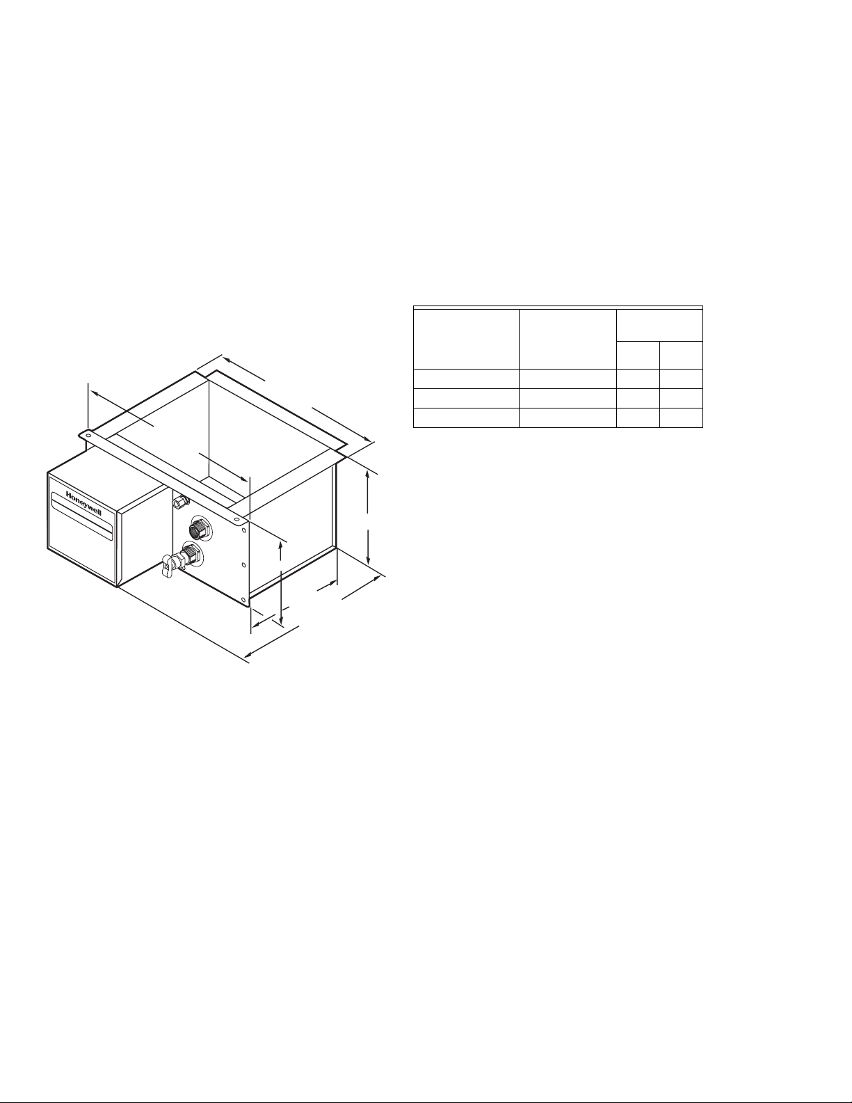
Dimensions:
Refer to Fig. 1.
11-7/8 (302)
12-5/8 (321)
HUMIDIFIER
HUMIDIFICATEUR
6 (152)
Approvals:
Underwriters Laboratories Inc.: Listing 42U8.
Canadian Underwriters Laboratories Inc.: Listing 42U8.
Models:
HE420A TRADELINE® Steam Power Humidifier package
includes mounting bracket and hardware, Automatic
Humidity Control, Automatic Flushing Timer with chlorine removal filter.
Table 1. Size Of Area That Can Be Humidified.
HE420A Area
(Up To)
House
Description
Air Changes
Per Hour
Sq. ft Sq. m
Loose Two 1,415 131
Average One 1,970 183
Tight One-half 3,095 288
7-5/8 (194)
9 (229)
12-1/2 (318)
M10534B
Fig. 1. Dimensions of HE420A in. (mm).
ORDERING INFORMATION
When purchasing replacement and modernization products from your TRADELINE® wholesaler or distributor, refer to the
TRADELINE® Catalog or price sheets for complete ordering number.
If you have additional questions, need further information, or would like to comment on our products or services, please write or
phone:
1. Your local Honeywell Automation and Control Products Sales Office (check white pages of your phone directory).
2. Honeywell Customer Care
1985 Douglas Drive North
Minneapolis, Minnesota 55422-4386
In Canada—Honeywell Limited/Honeywell Limitée, 35 Dynamic Drive, Toronto, Ontario M1V 4Z9.
International Sales and Service Offices in all principal cities of the world. Manufacturing in Australia, Canada, Finland, France,
Germany, Japan, Mexico, Netherlands, Spain, Taiwan, United Kingdom, U.S.A.
68-0192—4 2
Page 3
INSTALLATION
IMPORTANT
Read all the installation instructions before installing
the humidifier.
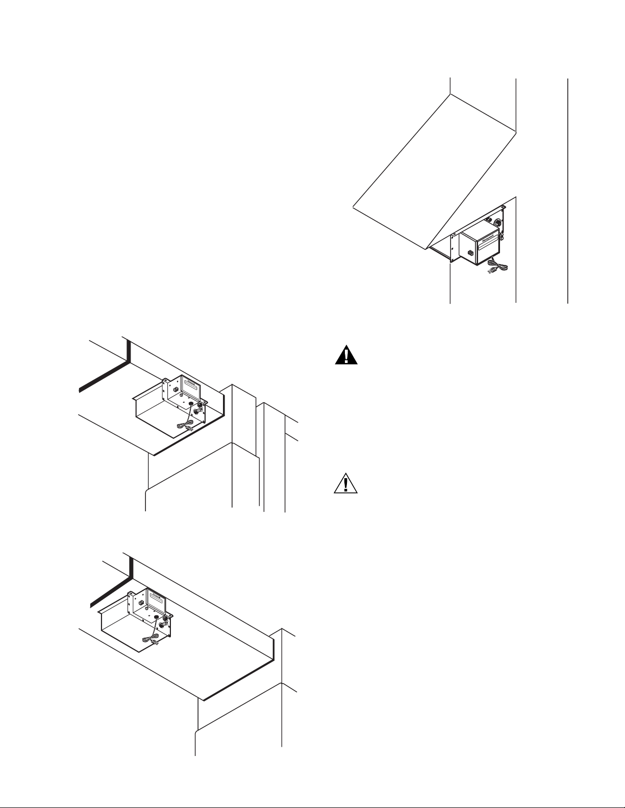
Select Location and Mount
There are three typical ways of mounting the steam humidifier:
• horizontally under at least a 10 in. (254 mm) wide duct using
the mounting bracket (preferred mounting);
• horizontally under a reinforced duct;
• horizontally under a duct extension using the mounting
bracket.
Decide which mounting is appropriate and follow those
mounting instructions. See Fig. 2 through 4.
Select a location where the humidifier can be plugged in
without an extension cord. The preferred installation location is
on the warm air side of the furnace. If that location is not
possible, mount the humidifier a minimum of 6 ft (1.8m)
upstream from the furnace filter. Depending on the location
selected, additional duct reinforcement may be necessary
because the humidifier weighs 18 lb. when filled with water.
HE420A STEAM POWER HUMIDIFIER
R
E
I
IF
R
ID
U
M
E
U
T
H
A
IC
F
I
D
I
M
U
H
M10580B
Fig. 4. Mounting humidifier horizontally under duct
extension using mounting bracket.
H
U
M
I
D
H
IF
U
IE
M
R
I
D
IF
IC
A
T
E
U
R
M10536B
Fig. 2. Mounting humidifier horizontally under duct using
mounting bracket.
H
UM
IDIFIER
H
UM
IDIFICATEUR
WARNING
Electrocution, Heavy Equipment and Chemical
Hazard.
Can cause death, blindness, water damage to
home and heater failure.
• Do not cut into any air conditioning or electrical line.
• Mount the humidifier in a level position to avoid
water damage and heater failure.
• Wear safety glasses when cutting or drilling.
• Reinforce duct as necessary to ensure stability.
CAUTION
Steam Condensation, Fire and Freezing Water
Hazard.
Can cause failure of fan or limit control or result in
water damage to home.
• Do not install the humidifier where the sidewalls of
the return air duct are constructed of wood (i.e., floor
joist).
• Do not install the humidifier where the temperature
is lower than 32°F (0°C) or higher than 200°F
(93°C).
Mount Horizontally Using Mounting Bracket (Preferred Mounting Method)
M10578B
Fig. 3. Mounting humidifier horizontally under duct.
IMPORTANT
The duct must be at least 10 in. (254 mm) wide to use
this mounting method.
The duct is the strongest when using the bracket mounting
method because the least amount of duct reinforcement is
required because of the bracket location. However,
reinforcement may still be necessary to help support the
weight of the humidifier and keep it level.
3 68-0192—4
Page 4

HE420A STEAM POWER HUMIDIFIER
1. Position the bracket 1/2 in. (13 mm) from the edge of the
duct and trace around the bracket. See Fig. 5.
2. Once the outline has been traced, remove bracket.
3. Drill a 3/8 in. (10 mm) hole within the center portion of
the bracket.
4. Use tin snips to cut around the outline of the bracket.
IMPORTANT
Follow the dotted line carefully.
5. Remove the sheet metal.
1/2 IN. (13 MM)
FROM EDGE
BRACKET
5. Remove sheet metal.
IMPORTANT
Do not mount the humidifier until the water level is
adjusted. See the Set The Water Level section.
6. Slide the flanges of the humidifier reservoir into the
mounting bracket.
7. Secure the humidifier to the duct with two no. 8 sheet
metal screws.
Mount Horizontally on Vertical Duct
Horizontal mounting on a vertical duct requires the installation
of a duct extension. See Fig. 4. Additional duct reinforcement
may also be necessary to help support the weight of the
humidifier and keep it level.
Create and install the duct extension. Then follow steps 1
through 8 in the Mount Horizontally Using Mounting Bracket
section to complete installation.
WIRING
All wiring must comply with local codes and ordinances. For
complete wiring instructions, refer to the manual “Wiring
Instructions for High-Capacity Steam Humidifiers” packaged
with your HE420A humidifier.
M23374
Fig. 5. Position bracket.
6.
Use two 8-32 screws and nuts to attach the mounting
bracket (L shaped with six holes) to the top/ front surface
of the humidifier. The humidifier is now ready for mounting.
NOTE: Position the humidifier so the upward protrusion of the
IMPORTANT
U is on the side toward the reservoir.
Do not mount the humidifier until the water level is
adjusted. See Set The Water Level section.
7. Slide the flanges of the humidifier reservoir into the
mounting bracket until the reservoir’s front flange comes
in contact with the edge of the duct.
8. Secure the humidifier to the duct with three no. 8 sheet
metal screws.
Mount Horizontally on Reinforced Duct
This horizontal mounting method usually requires duct
reinforcement to support the weight of the humidifier and keep
it level. See Fig. 3. The mounting bracket is not used.
1. Position the bracket to the bottom of the duct in the
desired location.
2. Once the outline has been traced, remove bracket.
3. Drill a 3/8 in. hole (10 mm) within the center portion of
the shaded area.
4. Use tin snips to cut around the outline of the bracket.
PLUMBING HUMIDIFIER
CAUTION
Chemical Hazard.
Can cause damage to environment or air
conditioning system.
Do not use any refrigerant line connected to an air
conditioner. Be sure to install the chlorine removal filter
(provided) to prevent humidifier corrosion.
Either hard or soft water can be used in the humidifier.
IMPORTANT
Use only copper tubing to plumb the humidifier.
1. Locate the cold water pipe closest to the humidifier.
2. Install the saddle valve connector.
3. Use the valve instructions to install the valve (provided).
The valve is self-piercing when installed on copper pipe.
IMPORTANT
Position the valve so water flows from the top or side to
reduce the chance of clogging the valve with minerals.
Lightly clean the copper tubing ends with fine sandpaper before making any connections.
4. Install the chlorine removal filter.
5. Place the brass compression nut over the copper tubing.
6. Slide the brass ferrule over the tubing.
NOTE: Do not overtighten the compression nut.
Moderate tightness prevents leaking.
IMPORTANT
Follow the dotted line carefully.
68-0192—4 4
7. Insert the tubing into the valve fitting and tighten the
compression nut.
Page 5

HE420A STEAM POWER HUMIDIFIER
8. Flush the copper tubing to remove any debris that can
cause problems at the float valve.
9. Route the tubing to the humidifier float valve, keeping the
tube away from sharp edges.
10. Connect the remaining end of the tubing to the humidifier
float valve.
11. Open the saddle valve so that the water flows slowly and
gently into the water pan.
SET WATER LEVEL
Adjust the humidifier water level prior to mounting.
1. Set the humidifier reservoir on a level surface.
2.
Attach the water feed line and allow the unit to fill until the
float valve shuts off the incoming flow of water. The water
level should be between 2-1/4 in. (57 mm) and 2-1/2 in.
(64 mm) deep. If water level is correct, go to step 4.
3. Adjust the water level in small increments. Raise the
water level by pushing down on the center of the float
arm. Lower the water level by pressing the float down
with one hand and pulling up on the center of the float
arm with the other hand. See Fig. 6.
CAUTION
Flooding Hazard.
Inadequate support of the float arm can lead to
valve seat damage and result in water leakage.
Support the float arm during adjustment.
TO RAISE WATER LEVEL
TO LOWER WATER LEVEL
6. Connect the overflow provision of the humidifier to a suit-
able waste drain.
NOTE: A 5/8 in. (16 mm) ID garden hose can be easily
attached to the overflow fitting.
7. Support the drain line at several locations to prevent
kinks. Be sure to provide support near any heat source.
8. Use a male 1-1/2 in. NPT fitting (not supplied) to connect
the overflow provision of the humidifier.
INSTALLING THE AUTOMATIC FLUSHING TIMER
Refer to the “Installation Instructions for the Programmable
Humidifier Automatic Flushing Timer” for complete instruction.
CHECKING THE INSTALLATION
After installation is complete, use the following procedure to
check the humidifier operation:
1. Turn on the humidifier water supply.
2.
Be sure the humidifier has power and plug in the humidifier.
3. Turn the Convertible Humidity Control to the Test
position.
4. Check that the furnace blower comes on to circulate the
moist air. The blower may take as long as fifteen minutes
to turn on.
5. Reset the Automatic Humidity Control to the desired dial
setting for automatic operation.
PUSH
DOWN
Fig. 6. Adjust water level.
4. Verify the water level by removing enough water to allow
the float valve to automatically fill and shut off the water.
HOLD
DOWN
PUSH
UP
M10581A
FINISH MOUNTING AND PLUMBING HUMIDIFIER
1. Mount humidifier as instructed in the Select Location and
Mount section.
2. Route the tubing to the humidifier float valve.
3. Connect the remaining end of the tubing to the humidifier
float valve.
4. Open the saddle valve so that the water flows slowly into
the water pan.
5. Check the compression fittings at the saddle valve and
the float valve. Tighten the fitting slightly to stop any
leakage.
IMPORTANT
Keep all drain lines away from sharp edges.
OPERATING THE HUMIDIFIER
The Honeywell HE420A Humidifier is controlled by an
Automatic Humidity Control. The Automatic Humidity Control is
mounted in the return air duct where it can be exposed to the
air stream of the return air, and is designed to automatically
adjust the humidity level based on indoor temperature and
humidity, inferred or measured outdoor temperature, and the
dial setting. The control allows for variations in furnace size,
window insulation and average daily climate temperature.
The Automatic Humidity Control requires an initial adjustment
period. Set the frost factor dial on 5 and use Table 2 to adjust
the dial–only one setting at a time–increasing the dial setting if
you feel you need more humidity, or reducing the setting if you
see moisture on the inside of your windows. For more precise
humidity adjustment, set the dial between dial settings. Allow
two days for the humidity level to subside before making
further adjustments. Once you have tuned in the proper
setting, you should not have to further adjust it again. The
control takes over and makes any future adjustments caused
by varying outdoor temperatures, thus reducing moisture
buildup on windows while maintaining the optimal humidity
level.
The Automatic Humidity Control can also be set for manual
operation. Once the control is installed in the cold air return
and internally set to MANUAL, turn the dial to the expected
outdoor temperature. The corresponding optimal humidity level
has been calibrated for you. For example, by setting the dial to
5 68-0192—4
Page 6

HE420A STEAM POWER HUMIDIFIER
an anticipated 20°F, the control automatically maintains the
indoor relative humidity in the safe, comfortable 35% range
(see Table 2).
Table 2. Automatic Humidity Control Settings.
Outside Temperature Recommended RH
+40°F 45%
+30°F 40%
+20°F 35%
+10°F 30%
0°F 25%
-10°F 20%
-20°F 15%
Table 3. Recommended Frost Factor Settings.
Humidity Level Recommended Adjustment
Insufficient
Increase the frost factor dial by one setting.
humidity
Condensation on
Decrease the frost factor dial by one setting.
windows
OPERATION
The HE420A Humidifier uses the principle that hot water
creates water vapor. As dry air and vapor mix, the relative
humidity of the air rises. The humidity control monitors the
relative humidity and activates the humidifier accordingly.
When the humidity control calls for humidity, the humidifier
underwater heater starts heating the water in the humidifier
reservoir. When the water is warm enough, the humidifier
activates a relay that turns on the furnace fan. The warm dry
air from the furnace picks up the water vapor and circulates it
through the home. The fan continues to circulate the air until
the water cools down and then turns off the fan.
Every 1 to 4 Months (Depending on Water Quality)
Use the following procedure and refer to Fig. 7 to clean the
humidifier:
1. Unplug the humidifier and fan control.
2. Disconnect the humidity control wires from the external
screw terminals on the humidifier.
3. Turn off the water supply.
HEATER
SAFETY
FLOATSWITCH
H
o
n
e
y
w
2
e
4
D
D
l
0
l
F
a
L
is
R
H
o
V
n
i
c
s
u
r
o
g
o
t
H
m
e
R
l
e
n
t
o
d
s
r
e
n
i
:
d
n
,
s
e
4
i
e
1
i
f
c
2
P
d
ie
y
t
P
U
b
e
w
o
r
e
h
e
n
8
s
e
M
l
a
f
t
s
e
l
o
ia
l,
s
i
c
o
b
r
e
l
t
e
d
I
l
r
n
e
U
,
i
e
c
s
c
6
s
l
e
a
e
.
0
H
e
l
l
r
1
e
v
s
E
H
O
8
c
i
u
c
4
t
8
z
n
r
p
in
6
,
5
i
ly
c
p
0
1
g
D
l
s
5
y
o
h
o
0
a
r
o
u
0
n
c
c
g
d
W
l
k
l
e
a
le
a
a
a
s
n
n
t
t
t
D
i
d
s
w
n
r
g
iv
b
a
.
u
t
e
e
r
.
r
n
.
c
M
o
i
o
n
l
n
e
a
p
o
l
i
s
,
M
L
R
N
i
s
t
5
e
5
d
4
4
2
2
2
U
3
8
9
9
2
O
T
U
EM
T
D
P
OO
ERAT
-2
R
0
F
-1
U
0
R
F
E
H
0
-30
+
F
UM
1
C
0
O
3
S
-25
+
I
F
D
E
v
2
40
0
IT
TT
e
0
C
-20
r 2
F
Y
IN
0
C
G
-10
F
15%
C
Over
20%
-5C
25%
2
0F
0
30%
35%
H
u
40%
m
R
i
d
é
it
g
y
u
C
la
o
te
50
n
u
tr
r
o
d'H
l
u
m
id
it
é
6
0
HUMIDITY
CONTROL
Fig. 7. Location of humidifier parts.
4. Disconnect water feed tubing at the float valve.
5. Disconnect the overflow at the humidifier.
IMPORTANT
Allow water to cool before continuing.
FLOAT
VALVE ARM
RESERVOIR
M23367
Humidified air feels warmer and more comfortable so you may
be able to lower the thermostat heating setpoint and save
money on heating fuel bills giving you a more comfortable
environment that is also energy efficient.
MAINTENANCE
A regular maintenance program prolongs the life of the
humidifier and provides a more comfortable environment.
Frequency of cleanings depends on water conditions. Either
hard or soft water can be used in the humidifier, but hard water
mineral deposits are more difficult to clean.
CAUTION
Voltage Hazard.
Can cause electrical shock and equipment damage.
Disconnect power supply before installing or servicing.
IMPORTANT
Never oil any part of the humidifier.
68-0192—4 6
6. Press and release the MANUAL button on the Automatic
Flushing Timer.
— Wait 10-30 seconds* until the flushing noise stops,
indicating that the flushing cycle is complete.
*The number of seconds will vary depending upon
how the unit is programmed. (See “Reprogramming
Instructions” in the Auto Flushing Timer Installation
Instructions)
— Repeat Steps A and B until the humidifier is drained.
7. Remove the humidifier from the mounting.
8. Use running tap water to flush loose minerals from the
reservoir.
9. Carefully rub off minerals from the float, heater, reservoir
walls, and safety float switch.
NOTE: Steel wool or other scouring pads can be used on the
reservoir walls and other parts.
10. Inspect the valve arm and float for mineral buildup and
deterioration.
IMPORTANT
• Replace the float valve when it shows any signs
of deterioration.
• The float valve should shut off the water at
2-3/8 in. (60 mm).
Page 7

HE420A STEAM POWER HUMIDIFIER
11. Reset the water level.
CAUTION
Flooding Hazard.
Inadequate support of the float arm can lead to
valve seat damage resulting in water leakage.
Support the float arm during adjustment.
a. Set the humidifier reservoir on a level surface.
b. Attach the water feed line and allow the unit to fill
until the float valve shuts off the incoming flow of
water. The water level should be between 2-1/4 in.
(57 mm) and 2-1/2 in. (64 mm) deep. If water level is
correct, go to step d.
c. Adjust the water level in small increments. Raise the
water level by pushing down on the center of the
float arm. Lower the water level by pressing the float
down with one hand and pulling up on the center of
the float arm with the other hand. See Fig. 6.
d. Verify the water level by removing enough water to
allow the float valve to automatically fill and shut off
the water.
12. Remount the humidifier.
13. Reconnect all plumbing connections.
14. Reconnect all electrical connections.
15. Verify humidifier operation by following the steps in the
Checkout Procedures section.
End of Humidification Season
Clean and shut off the humidifier at the end of the heating
season. Use the Every 1 To 4 Months section, steps 1 through
14, to shut down for the season.
IMPORTANT
Be sure the humidifier power is off and there is no
water in the humidifier.
Vacation
When you leave on vacation, turn off the humidifier water
supply and the humidity control. When you return, turn on the
humidifier water supply and reset the humidity control to restart
the humidifier.
CHECKOUT PROCEDURES
After winter start-up or maintenance, use the following
procedure to check humidifier operation:
1. Turn on the humidifier water supply.
2.
Be sure the humidifier has power and plug in the humidifier.
3. Turn the Automatic Humidity Control to the Test position.
NOTE: If relative humidity is above 45% in the home, or the
outdoor temperature is above 50°F, a jumper may
need to be placed across the humidistat’s OUT terminals to perform this checkout.
4. Check that the furnace blower turns on to circulate the
moist air. The blower may take as long as fifteen minutes
to turn on.
5. Reset the Automatic Humidity Control to the desired dial
setting for automatic operation.
TROUBLESHOOTING
Refer to Table 4 for troubleshooting procedures.
Table 4. Troubleshooting Procedures.
Problem What To Look For What To Do
Low humidity Humidifier heater is not operating. • Confirm that humidifier is plugged in.
• Set the humidistat higher.
• Check for low water level.
• Reset circuit breaker or check for blown fuse.
• Check that the furnace power is on.
• Check all external wiring connections.
• Check the humidity control setting.
• Call a professional heating contractor.
Rapid air changes. Drafts (cold air is dry
and is an added load for the humidifier).
High humidity Condensation on walls. • Turn off humidity control and water until condensation is
Heavy condensation on windows. • Turn humidity control down low enough to eliminate
• Keep doors and windows closed.
• Close fireplace damper when not in use.
• Keep exhaust fan running time to a minimum.
• Seal around doors and windows.
completely evaporated.
condensation caused by moisture from bathing, mopping,
cooking, etc. If moisture persists, more ventilation is
needed.
7 68-0192—4
Page 8

HE420A STEAM POWER HUMIDIFIER
REPLACEMENT PARTS
Refer to Fig. 14 and Table 5 when ordering replacement parts.
1
5
2
8
9
10
11
6
12
13
7
O
v
e
H
R
3
4
Model HE460
Only
atts
1500 W
ater cool
Honeywell Humidifier
hock and burn.
For Residential Use
olts, 1 Phase, 60 Hz,
r cleaning.
al supply and let w
240 V
Possible electric s
Danger:
before servicing o
R
Disconnect electric
Listed 42U8
R
5422-3992
Listed 42U8
e. Minneapolis, MN 5
Honeywell, Inc.
1885 Douglas Driv
14
15
OU
TE
T
M
D
P
O
ERA
-2
O
R
0
F
-1
T
UR
0F
E
HU
0
-30
+
F
1
M
C
0
3
SE
-25
+
I
F
D
2
4
0
ITY
TT
0F
C
-20
r
0
2
IN
0
C
G
-10
F
15%
C
Over
20%
-5C
25%
2
0F
0
30%
35%
u
40%
m
i
d
é
ity
g
u
C
la
o
t
e
50
n
u
tr
r d
o
l
'H
u
m
id
it
é
60
16
M23366
Fig. 8. Exploded view of humidifier parts.
Table 5. List of Replacement Parts for HE420A Humidifier
Exploded
View Number Description
1 Incoloy® sheathed heating
element
2 Safety float switch 32000149-001
3 Float for water fill valve 32000166-001
HE420A Part
Number
32000164-001
Exploded
View Number Description
11 Indicator light 32000158-001
12 Thermal fan switch 32000159-001
13 Power distribution block 32000160-001
14 Power supply cord with strain
4 Water fill valve 32000167-001
5 Water pan assembly 32000152-001
6 Electrical enclosure cover 32000169-001
7 Transformer, 24 Vac AT120B1101
8 Control relay, dpst, 24 V 50018844-001
9 Fan wiring assembly 32000156-001
10 Humidistat control terminal
32000157-001
block
15 Saddle valve assembly 32001616-001
16 Automatic Humidity Control H1010A1004
— Automatic Flushing Timer 50018842-001
— Safety Control Shutoff 50018846-001
— SPDT Relay 50018847-001
— Mounting Bracket Frame 50018841-001
— Chlorine Filter 50019240-001
Automation and Control Solutions
Honeywell International Inc. Honeywell Limited-Honeywell Limitée
1985 Douglas Drive North 35 Dynamic Drive
Golden Valley, MN 55422 Toronto, Ontario M1V 4Z9
customer.honeywell.com
HE420A Part
Number
32000177-001
relief
® U.S. Registered Trademark
© 2006 Honeywell International Inc.
68-0192—4 M.S. Rev. 07-06
 Loading...