

Honeywell He440a, He480a, He440a1005, He440a1003, He440 Installation Instruction
...
READ AND SAVE THESE INSTRUCTIONS
HE420A Steam Power Humidifier
INSTALLATION INSTRUCTIONS
APPLICATION
The HE420A Steam Power Humidifier uses a thermal fan
interlock control to provide humidification for the whole
house. The steam power humidifier is designed to work
with high efficiency furnaces and heat pumps.
INSTALLATION
IMPORTANT
This product is for residential applications only
and must be installed by a qualified HVAC contractor. Failure to comply could invalidate the
product warranty, or result in serious injury or
electrocution.
SELECT LOCATION AND MOUNT
WARNING
Electrocution, Heavy Equipment and
Chemical Hazard.
Can cause death, blindness, water damage to
home and heater failure.
• Do not cut into any air conditioning or
electrical line.
• Wear safety glasses when cutting or drilling.
• Mount the humidifier in a level position to
avoid water damage and heater failure.
• Reinforce duct as necessary to ensure
stability.
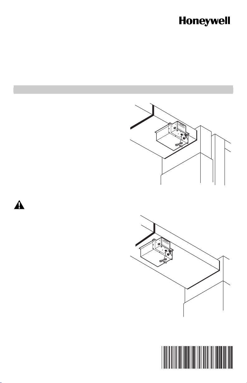
There are three typical ways of mounting the steam
humidifier. See Fig. 1, 2, and 3. Be sure to select a
location where the humidifier can be plugged in without
an extension cord. The preferred installation location is
on the warm air side of the furnace. If that location is not
possible, the humidifier should be mounted a minimum of
6 ft (1.8m) upstream from the furnace filter. Depending
on the location selected, additional duct reinforcement
may be necessary because the humidifier weighs 18 lb
when filled with water.
Fig. 1. Mount humidifier horizontally under duct
using mounting bracket.
HU
M
ID
H
IFIE
UM
R
ID
IFICATEU
R
H
UM
ID
H
IFIER
U
MIDIFICATEU
R
M10536B
M10578B
Fig. 2. Mount humidifier horizontally under duct.
69-1108-2
HE420A STEAM POWER HUMIDIFIER
HUMIDIFIER
HUMIDIFICATEUR
Mount Horizontally Using Mounting Bracket (Preferred Mounting Method)
IMPORTANT
The duct must be at least 10 in. (254 mm) wide
to use this mounting method.
The duct is strongest when using the bracket mounting
method because the least amount of duct reinforcement
is required because of the bracket location. See Fig. 1.
However, in some installations, reinforcement may still be
necessary to help support the weight of the humidifier and
keep the humidifier level.
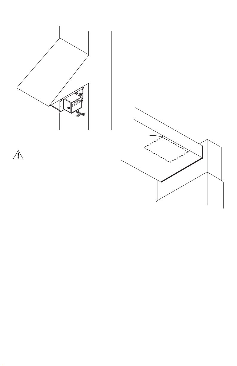
1.
Position the bracket 1/2 in. (13 mm) from the edge of
the duct and trace around the bracket. See Fig. 4.
2. Once the outline has been traced, remove bracket.
M10580B
Fig. 3. Mount humidifier horizontally under duct
extension using mounting bracket.
CAUTION
Steam Condensation, Fire and Freezing Water
Hazard.
Can cause failure of fan or limit control or
result in water damage to home.
• Do not install the humidifier where the
sidewalls of the return air duct are constructed
of wood (i.e. floor joist).
• Do not Install the humidifier where the
temperature is lower than 32°F (O°C) or higher
than 200°F (93°C).
• For all installation configurations, the mounting
area must be strong enough to support the
humidifier's weight when it is full of water
(approximately 18 lbs.), and to hold the
humidifier in a level position for safe, reliable
operation. Otherwise, additional duct
reinforcement will be necessary.
• If the installation includes exposed insulated
materials, a section of the ductwork must be
removed and replaced with rigid metal duct
extending at least 6 feet downstream from the
humidifier.
• Mount the unit at least 4-to-6 feet after the
plenum transition. Avoid sudden turns or
transitions in the ductwork in the immediate
area downstream from the humidifier.
There are three possible mounting procedures:
• horizontally under at least a 10 in. (254 mm) wide duct
using the mounting bracket (preferred mounting);
• horizontally under a reinforced duct;
• horizontally under a duct extension using the mounting
bracket.
Decide which mounting is appropriate and follow those
mounting instructions.
1/2 IN. (13 MM)
FROM EDGE
BRACKET
M23374
Fig. 4. Position bracket to duct edge.
3. Drill a 3/8 in. (10 mm) hole within the center portion
of the bracket.
4. Use tin snips to cut around the outline of the
bracket.
IMPORTANT
Follow the dotted line carefully.
5. Remove the sheet metal.
6. Use two 8-32 screws and nuts to attach the mount-
ing bracket (L shaped with six holes) to the top/front
surface of the humidifier. The humidifier is now
ready for mounting.
NOTE: Position the humidifier so the upward protrusion
of the U is on the side toward the reservoir.
IMPORTANT
Do not mount the humidifier until the water level
is adjusted. See the Plumbing section.
7. Slide the flanges of the humidifier reservoir into the
mounting bracket until the reservoir’s front flange
comes into contact with the edge of the duct.
8. Secure the humidifier to the duct with three no. 8
sheet metal screws.
69-1108—2 2
HE420A STEAM POWER HUMIDIFIER
A
Mount Horizontally On Reinforced Duct
This horizontal mounting method usually requires duct
reinforcement to support the weight of the humidifier and
keep it level. The mounting bracket is not used. See Fig. 2.
1. Position the bracket to the bottom of the duct in the
desired location. Be sure the bracket is level.
2. Once the outline has been traced, remove bracket.
3. Drill a 3/8 in. (10 mm) hole within the center portion
of the bracket.
4. Use tin snips to cut around the outline of the
bracket.
5. Remove the sheet metal.
IMPORTANT
Do not mount the humidifier until the water level
is adjusted. See the Plumbing section.
6. Slide the flanges of the humidifier reservoir into the
mounting bracket.
7. Secure the humidifier to the duct with two no. 8
sheet metal screws.
Mount Horizontally On Vertical Duct
Horizontal mounting on a vertical duct requires the
installation of a duct extension. Additional duct
reinforcement may also be necessary to help support the
weight of the humidifier and keep it level. See Fig. 3.
Create and install the duct extension. Follow the steps in
the Mount Horizontally Using Mounting Bracket section to
complete installation.
WIRING
All wiring must comply with local codes and ordinances.
For complete wiring instructions, refer to the manual
“Wiring Instructions for High-Capacity Steam Humidifiers”
packaged with your HE420A humidifier.
PLUMBING THE HUMIDIFIER
CAUTION
Chemical Hazard.
Can cause damage to environment or air
conditioning system.
Do not use any refrigerant line connected to an air
conditioner.
Be sure to install the chlorine removal filter
(provided) to prevent humidifier corrosion.
NOTE: Either hard or soft water can be used in the
humidifier.
IMPORTANT
Use only copper tubing to plumb the humidifier.
1. Locate the cold water pipe closest to the humidifier.
2. Install the saddle valve connector.
3. Use the valve instructions to install the valve (pro-
vided). The valve is self-piercing when installed on
copper pipe.
IMPORTANT
Position the valve so water flows from the top or
side to reduce the chance of clogging the valve
with minerals.
Lightly clean the copper tubing ends with fine
sandpaper before making any connections.
Do not use any line connected to an air
conditioner.
4. Install the chlorine removal filter.
5. Place the brass compression nut over the copper
tubing.
6. Slide the brass ferrule over the tubing.
NOTE: Do not overtighten the compression nut.
Moderate tightness prevents leaking.
7. Insert the tubing into the valve fitting and tighten the
compression nut.
8. Flush the copper tubing to remove any debris that
can cause problems at the float valve.
9. Route the tubing to the humidifier float valve, keep-
ing the tube away from sharp edges.
10. Connect the remaining end of the tubing to the
humidifier float valve.
11. Open the saddle valve so that the water flows
slowly and gently into the water pan.
SET THE WATER LEVEL
CAUTION
Flooding Hazard.
Inadequate support of the float arm can lead to
valve seat damage resulting in water leakage.
Support the float arm during adjustment.
Adjust the humidifier water level prior to mounting.
1. Set the humidifier reservoir on a level surface.
2. Attach the water feed line and allow the unit to fill
until the float valve shuts off the incoming flow of
water. The water level should be between 2-1/4 in.
(57 mm) and 2-1/2 in. (64 mm) deep. If water level
is correct, skip to step 4.
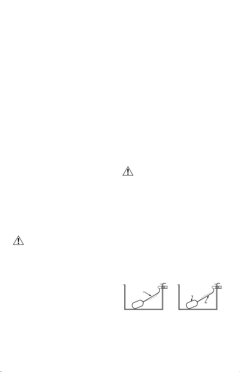
3. Adjust the water level in small increments. Raise
the water level by pushing down on the center of
the float arm. Lower the water level by pressing the
float down with one hand and pulling up on the center of the float arm with the other hand. See Fig. 5.
4. Verify the water level by removing enough water to
allow the float valve to automatically fill and shut off
the water.
TO RAISE WATER LEVEL
PUSH
DOWN
Fig. 5. Adjusting the water level.
TO LOWER WATER LEVEL
HOLD
DOWN
PUSH
UP
M10581
369-1108—2
 Loading...