

Page 1
+($%
3RZHUHG)ORZ7KURXJK+XPLGLILHU
)($785(6
• Capable of humidifying the largest areaup to 4200
sq ft (390 sq m)of any Honeywell flow-through
humidifier.
• Includes the PerfectFlo™ water distribution tray for
optimal efficiency and water usage.
• Proven technology used for high performance
humidification.
• Narrower footprint than popular compatible model
while maintaining a common humidifier pad and
comparable humidification performance.
• Interior components designed for quick maintenance
and service.
HE360
M12807
$33/,&$7,21
The HE360A,B Powered Flow-Through Humidifiers work with
the warm air furnace blower to provide humidification for the
whole house. The HE360A,B works with virtually any
Honeywell humidity control, and can be integrated to the
temperature control in the home, when controlled by the
Honeywell Perfect Climate Comfort Center™ control.
• HE360A Humidifier includes a convertible humidity
control that mounts on the wall or duct for more
flexibility.
• HE360B Humidifier includes the Automatic Humidity
Control with HumidCalc+™ that automatically adjusts
humidity level and eliminates moisture build-up.
• Perfect Climate Comfort Center™ control can be
installed to replace both the thermostat and humidity
control for improved aesthetics and convenience.
• Continuous flushing reduces the maintenance
frequency.
&RQWHQWV
Application........................................................................... 1
Features.............................................................................. 1
Specifications...................................................................... 2
Installation........................................................................... 3
Wiring Humidifier................................................................. 4
Checking Installation........................................................... 6
Operating Humidifier........................................................... 6
Operation ............................................................................ 6
Maintenance........................................................................ 7
Checkout Procedure ........................................................... 8
Troubleshooting .................................................................. 8
Replacement Parts.............................................................. 9
®U.S. Registered Trademark
Copyright © 1999 Honeywell Inc. • All Ri ghts Reserved
68- 0194- 2
Page 2
HE360A,B POWERED FLOW-THROUGH HUMIDIFIER
63(&,),&$7,216
IMPORTANT
The specifications given in this publication do not
include normal manufacturing tolerances. Therefore,
this unit may not exactly match the listed
specifications. Also, this product is tested and
calibrated under closely controlled conditions and
some minor differences in performance can be
expected if those conditions are changed.
TRADELINE® Models Available:
HE360A: Includes humidifier, humidifier pad, mounting
template, self-piercing saddle valve and H908 Convertible
Humidity Control.
HE360B: Includes humidifier, humidifier pad, mounting
template, self-piercing saddle valve and H1008 Automatic
Humidity Control.
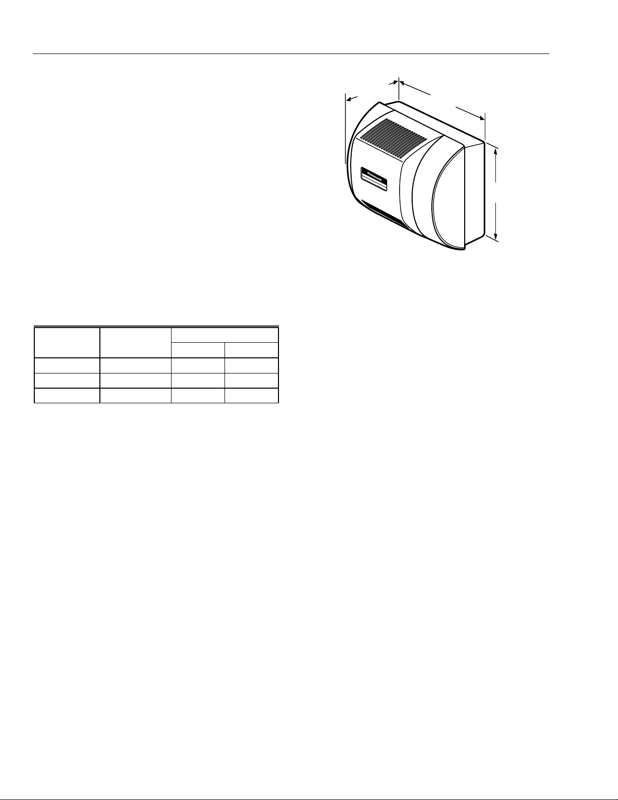
10-1/4 (260)
14 (356)
15-1/4
M12811
(387)
Capacity:
At 120°F (49°C) plenum temperature and 0.20 static
pressure drop across supply and return: 18 gallons per day
(gpd), 68 liters per day (lpd).
Humidified Area:
House Air Changes
Description Per Hour
Area (Up To)
Sq ft Sq m
Loose Two 1,900 175
Average One 2,700 248
Tight One-half 4,200 386
Electrical Ratings:
120 Vac, 60 Hz, 0.7A.
Humidifier Pad Dimensions (height x width x depth):
13 in. x 10 in. x 1-1/2 in. (330 mm x 254 mm x 38 mm).
Plenum Opening Dimensions (height x width):
14-1/16 in. x 13-1/2 in. (357 mm x 343 mm).
Drain Connection:
1/2 in. (13 mm) I.D. plastic hose connected directly to drain
fitting on unit.
Dimensions:
Refer to Fig. 1.
Fig. 1. HE360A,B dimensions in in. (mm).
Approvals:
Underwriters Laboratories Inc.: Listing Pending.
Canadian Underwriters laboratories Inc.: Listing Pending.
Standards:
Air Conditioning and Refrigeration Institute Tested:
Standard 610.
Accessories:
C7089H Outdoor Temperature Sensor.
H908A Convertible Humidity Control.
H1008A Automatic Humidity Control.
HC26A Humidifier Pad.
PC8900 Perfect Climate Comfort Center™ Control.
S688A Sail Switch.
Current Sensing Relay, part no. 32001754-001.
25'(5,1*,1)250$7,21
When purchasing replacement and modernization products from your TRADELINE® wholesaler or distributor, refer to the
TRADELINE® Catalog or price sheets for complete ordering number.
If you have additional questions, need further information, or would like to comment on our products or services, please write
or phone:
1. Your local Home and Building Control Sales Office (check white pages of your phone directory).
2. Home and Building Control Customer Logistics
Honeywell Inc., 1885 Douglas Drive North
Minneapolis, Minnesota 55422-4386 (612) 951-1000
In Canada—Honeywell Limited/Honeywell Limitée, 155 Gordon Baker Road, North York Ontario M2H 3N7.
International Sales and Service Offices in all principal cityies of the world. Manufacturing in Australia, Canada, Finland, France,
Germany, Japan, Mexico, Netherlands, Spain, Taiwan, United Kingdom, U.S.A.
68-0194—2 2
Page 3
,167$//$7,21
:KHQ,QVWDOOLQJWKLV3URGXFW
1. Read these instructions carefully. Failure to follow
them could damage the product or cause a
hazardous condition.
2. Check the ratings given in the instructions and on
the product to make sure the product is suitable for
your application.
3. Installer must be a trained, experienced service
technician.
4. After installation is complete, check out product
operation as provided in these instructions.
CAUTION
Personal Injury or Equipment Hazard.
Improper drilling can cause equipment damage
or personal injury.
Do not cut or drill into any air conditioning or
electrical accessory.
CAUTION
Property or Equipment Hazard.
Can cause property or equipment damage.
• Locate the humidifier where the ambient
temperature is between 32°F (0°C) and 160°F
(71°C).
• Do not install where freezing temperatures could
occur.
• Be sure supply plenum static pressure is no
greater than 0.4 in. wc and water pressure is no
greater than 125 psi.
/RFDWLRQDQG0RXQWLQJ
IMPORTANT
Mount the humidifier at least 3 in. (76 mm) above
the furnace jacket to allow adequate space for the
drain line. Check that there is adequate space
above the humidifier to remove and install the
humidifier cover. Do not install on a furnace
jacket.
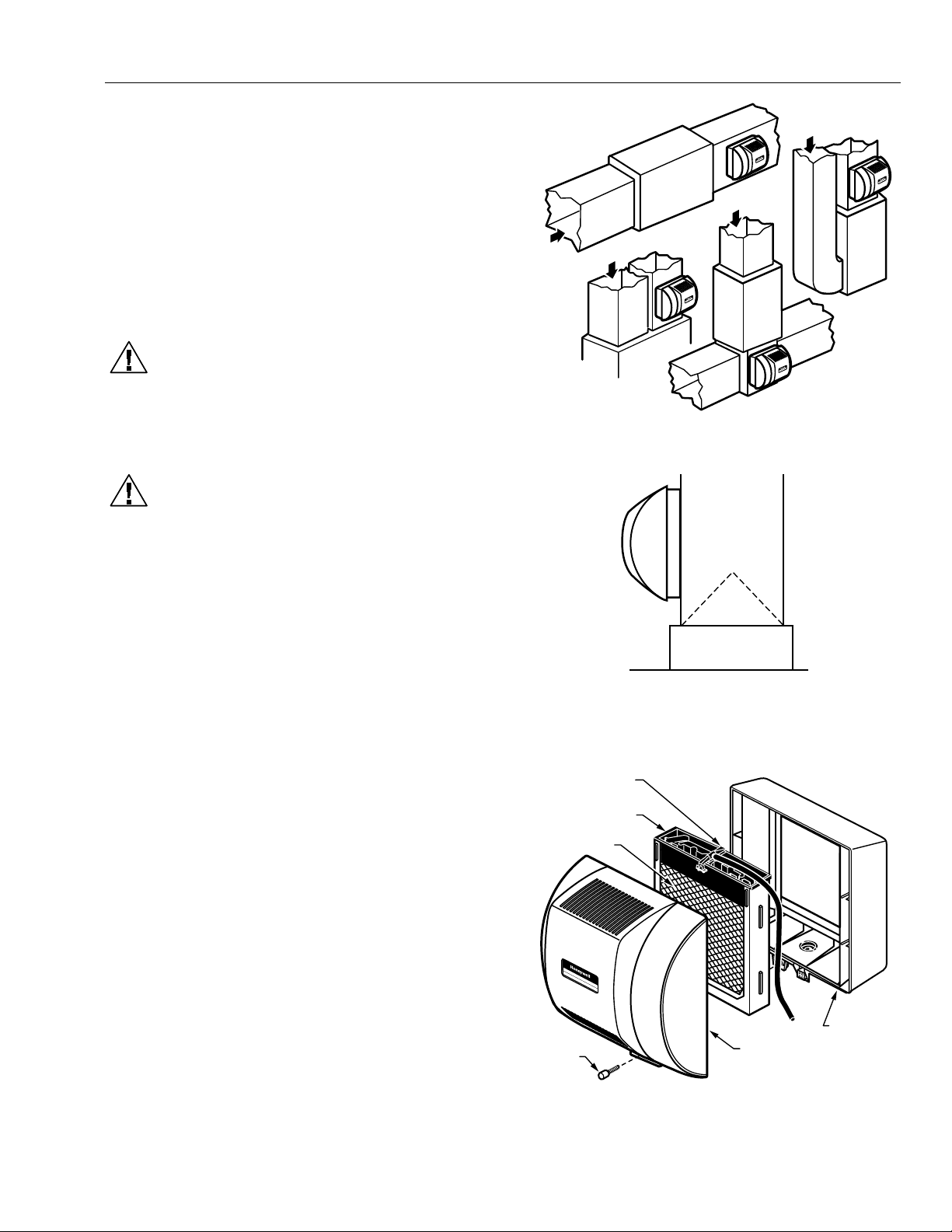
1. Determine the best location for the humidifier and
draw a level line on the plenum. See Fig. 2 and 3.
HE360A,B POWERED FLOW-THROUGH HUMIDIFIER
RETURN
HORIZONTAL
RETURN
RETURN
RETURN
LOWBOY
DOWN
FLO
Fig. 2. Typical humidifier installation locations.
M12812
Fig. 3. HE360 Humidifier location in relation to air
conditioning cooling coils.
FEED TUBE NOZZLE
WATER
DISTRIBUTION TRAY
HUMIDIFIER
PAD ASSEMBLY
HIGHBOY
M12808
IMPORTANT
Be sure the template is level before marking to
assure optimal product performance.
2. Tape the template in position and trace around the
template.
3. Remove the template and carefully cut the
rectangular opening.
4. Loosen the thumbscrew on the bottom of the
humidifier and remove the cover.
5. Remove the humidifier pad assembly by grasping
the top of the tray and pulling the assembly out of
the housing. See Fig. 4.
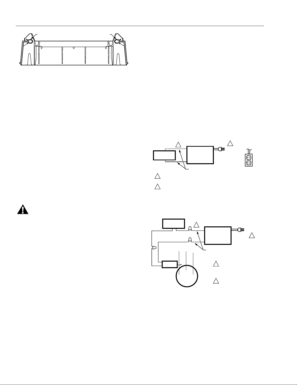
6. Position the securing clips as shown in Fig. 5.
completely seat them.
Do not
HUMIDIFIER
THUMB
SCREW
COVER
ASSEMBLY
HOUSING
M12809
Fig. 4. Humidifier components.
3 68-0194—2
Page 4
HE360A,B POWERED FLOW-THROUGH HUMIDIFIER
CLIP
CLIP
Fig. 5. Position securing clips.
7.
Position the humidifier housing in the hole (be sure it
is level), so the locking tabs are in place on the
upper and lower sheet metal edges of the hole.
8.
Push in the securing clips until completely seated.
9.
Drill holes and install the three sheet metal screws at
the top of the humidifier housing. Secure the housing
with the three remaining screws at the bottom of the
housing.
10.
Reinstall the humidifier pad assembly in the
humidifier housing.
IMPORTANT
For proper operation, be sure the mark on the
end of the humidifier pad is facing up. Check that
the water feed tube is placed in the guide slots of
the humidifier housing.
11.
Hook the top of the cover to the housing and secure
with the thumbscrew located at the bottom of the
cover.
M12813
1. Wire the current sensing relay or sail switch.
2. Connect only the two yellow wires to the humidity
control (red wire connections are not used for
mechanical humidity control). See the typical wiring
diagrams in Fig. 6 through 8.
For additional mounting and wiring information, refer to the
humidity control installation instructions.
)RU+$XWRPDWLF+XPLGLW\&RQWURO:LULQJ
&RQQHFWLRQV
IMPORTANT
For additional mounting and wiring information, refer to the
humidity control installation instructions.
Current sensing relay or sail switch is not needed
with the Automatic Humidity Control.
1. Connect the two red and two yellow wires to the
electronic humidity control as shown in Fig. 9.
TO BLOWER
MOTOR
2
MECHANICAL
HUMIDISTAT
1
POWER SUPPLY. PROVIDE DISCONNECT MEANS AND
OVERLOAD PROTECTION AS REQUIRED.
24V WIRING.
2
HUMIDIFIER
YELLOW WIRES
1
120 VAC
IGNITION BOX
M12686
:,5,1*+80,',),(5
WARNING
Serious Personal Injury or Equipment Hazard.
Moving parts can cause electrical shock and
injury.
• Disconnect power supply before installation or
servicing.
• This device contains a moving fan blade; do not
operate the humidifier without the cover
All wiring must comply with applicable local codes,
ordinances and regulations.
)RU++XPLGLVWDW+&RQYHUWLEOH+XPLGLW\
&RQWURO:LULQJ&RQQHFWLRQV
IMPORTANT
securely attached.
• Select models of fan centers include humidifer
taps so the current sensing relay or sail switch is
not needed.
• If not using a current sensing relay or sail switch,
the 120V humidifier plug must be energized
during blower motor cycles for proper operation.
Fig. 6. Typical wiring diagram for humidifier using fan
control to cycle blower motor fan and humidifier
simultaneously.
MECHANICAL
HUMIDISTAT
CURRENT
SENSING
RELAY
BLOWER
MOTOR
C
LO
2
HUMIDIFIER
YELLOW WIRES
1
POWER SUPPLY.
PROVIDE DISCONNECT
MEANS AND OVERLOAD
HI
PROTECTION AS REQUIRED.
2
24V WIRING.
120 VAC
1
M12684
Fig. 7. Typical wiring diagram of current sensing relay
with humidifier.
68-0194—2 4
Page 5

HE360A,B POWERED FLOW-THROUGH HUMIDIFIER
Fig. 8. Typical wiring diagram of sail switch with humidifier.
120
VAC
1
HUMIDIFIER
1
POWER SUPPLY. PROVIDE DISCONNECT MEANS
AND OVERLOAD PROTECTION AS REQUIRED.
2
24V WIRING.
2
CONNECTOR
YELLOW
YELLOW
BLACK
BLACK
1
RED
RED
SOLENOID
MECHANICAL
HUMIDISTAT
SAIL
SWITCH
2
HUMIDIFIER
YELLOW WIRES
1
POWER SUPPLY. PROVIDE DISCONNECT
MEANS AND OVERLOAD PROTECTION
AS REQUIRED.
2
24V WIRING.
DEHUM
DEHUM
HUM
K1
HUM
HOT
COM
24VAC
ELECTRONIC HUMIDISTAT
3
HEAT ONLY APPLICATIOIN SHOWN. SIMILAR WIRING
REQUIRED IN HEAT AND COOL SYSTEM WITH ONE
OR TWO TRANSFORMERS.
OUT
OUT
G
CG
CW
W
120 VAC
1
M12685
FROST FACTOR
SETPOINT DIAL
ROOM THERMOSTAT
G
FAN
RELAY
W
HEAT
RELAY
R
3
FURNACE
TRANSFORMER
M12820A
L1
(HOT)
L2
1
Fig. 9. Typical wiring diagram for humidifier using H1008 Automatic Humidity Control.
)RU3HUIHFW&OLPDWH&RPIRUW&HQWHU&RQWURO
&RQQHFWLRQV
1.
Connect only the two yellow wires to the W8900 (red
wire connections are not used). See the typical
wiring diagram in Fig. 10.
For additional mounting and wiring information, refer to the
Perfect Climate Comfort Center installation instructions.
3OXPELQJ6DGGOH9DOYH
Hot or cold water, either hard or softened, can be used in
the humidifier.
1. Use the self-piercing saddle valve included to tap
into the water supply line at an appropriate location.
CAUTION
Equipment Hazard.
Improper installation can cause equipment
damage.
Do not use any line connected to an air
conditioner.
PC8900
1
2
3
4
HE360
HUMIDIFIER
RED
RED
3
YELLOW
YELLOW
2
120
VAC
1
1
POWER SUPPLY. PROVIDE DISCONNECT MEANS AND OVERLOAD
PROTECTION AS REQUIRED.
2
OPTIMAL CONTROL ACHIEVED WHEN USING OUTDOOR AIR SENSOR.
W8900B
2
OPTIONAL
OUTDOOR
AIR SENSOR
M12819
Fig. 10. Typical wiring diagram for humidifier using
PC8900/W8900.
5 68-0194—2
Page 6

HE360A,B POWERED FLOW-THROUGH HUMIDIFIER
IMPORTANT
• The saddle valve is not designed to regulate
water flow; the valve is either open or closed.
• Be sure to install the saddle valve handle pointing
toward the ceiling to prevent debris from clogging
the solenoid in-line filter.
NOTE: Lightly clean the copper tubing ends with
2.
Use 1/4 in. O.D. copper tubing and connect the
saddle valve to the inlet side of the solenoid valve.
NOTE: Do not over-tighten the compression nut.
3.
Connect a 1/2 in. hose to the humidifier drain fitting
and run it to a suitable drain.
NOTE: Slope the hose downward for correct
fine sandpaper before making any
connections.
a. Place the brass compression nut over the
copper tubing.
b. Slide the brass ferrule over the tubing.
Moderate tightness prevents leaking.
c. Insert the tubing into the solenoid valve fitting
and support the valve while tightening the
compression nut.
drainage.
&+(&.,1*,167$//$7,21
1. Open the saddle valve.
NOTE: The furnace blower must be operating for
2. Set the thermostat setpoint 10°F (12°C) above the
room temperature.
3. Set the humidity control to a high humidity setting, or
place the humidity control in the test position.
4. Observe the water running out of the drain line to be
sure the humidifier is working correctly.
5. Check for leaks.
6. Reset the thermostat and humidity control to
comfortable settings.
the humidifier to work.
23(5$7,1*+80,',),(5
The Honeywell HE360A Humidifier is controlled by the
H908 Convertible Humidity Control. The convertible
humidity control is installed either on an interior wall in the
living area, or on the return air duct. Choose the humidity
control setting using the combination relative
humidity/outdoor temperature setting scale on the humidity
control dial. Match the dial setting to the outdoor
temperature for optimizing the humidity level to reduce the
moisture condensation on your windows. The table below
can also be used to adjust the humidity control to the
recommended setting.
NOTE: As outside temperature drops, the recommended
humidity control setting is lowered to
accommodate the effects of dewpoint. These
settings should reduce the accumulation of
moisture and ice on the windows and in other
areas of the house.
Some indoor activities such as cooking, showering and
clothes drying can cause excessive levels of humidity and
start the accumulation of moisture on the windows. If this
condition persists for more than a few hours, set the
humidistat to the lowest setting to turn off the humidifier. If
the condition does not improve, ventilate the house to
remove the moisture.
The Honeywell HE360B Humidifier is controlled by the
Honeywell H1008 Automatic Humidity Control with
HumidCalc+. The automatic humidity control is mounted
in the return air duct where it can be exposed to the air
stream of the return air. The HumidCalc+software inside
the automatic humidity control is designed to measure or
infer the outdoor temperature and automatically adjust the
humidity based on the frost factor. The frost factor is set by
the homeowner and allows for variances in furnace size,
window type and insulation. The Automatic Humidity
Control with HumidCalc+ requires initial adjustment when
first installing the HE360B. Set the frost factor dial to 5 and
use Table 2 to adjust the frost factor, one setting at a time,
increasing the dial setting for more humidity, or reducing
the setting if moisture starts to build up on the inside of
your windows. Allow two days between adjustments to
determine if further adjustment is necessary. Once the
frost factor has been set, no further adjustment is needed.
23(5$7,21
The HE360A,B Humidifiers use the principle that vapor
(evaporated water) is created when warm dry air blows
over a water-soaked area. As the vapor circulates, the
relative humidity rises.
The humidity control monitors the relative humidity and
activates the humidifier accordingly. The humidifier has a
water supply that disburses water over a humidifier pad.
The warm dry air from the furnace passes over the
humidifier pad, collects moisture, and circulates it through
the house.
Since humidified air feels warmer and more comfortable,
the homeowner may decide to lower the thermostat
setpoint, thus saving money on heating bills. The end
result is that the humidifier provides a more comfortable
environment that is also energy efficient.
Table 1. Recommended Humidity Control Settings.
Outside Temperature Recommended Setting Outside Temperature Recommended Setting
-20°F (-29°C) 15 +10°F (-12°C) 30
-10°F (-23°C) 20 +20°F (-7°C) 35
0°F (-18°C) 25 +20°F (-7°C) 40
68-0194—2 6
Page 7

HE360A,B POWERED FLOW-THROUGH HUMIDIFIER
Table 2. Recommended Frost Factor Adjustment.
Humidity Level Recommended Setting
Insufficient humidity Increase the frost factor dial be one setting
Condensation on windows Reduce the frost factor dial by one setting.
0$,17(1$1&(
A regular maintenance program prolongs the life of the
humidifier and provides a more comfortable environment.
Frequency of cleanings depends on water conditions.
Either hard or soft water can be used in the humidifier, but
hard water mineral deposits are more difficult to clean then
soft water deposits.
Use the following procedure to clean the humidifier.
CAUTION
Personal Injury or Equipment Hazard.
Power Supply can cause electrical shock or
equipment damage.
Disconnect power supply before performing
humidifier maintenance.
IMPORTANT
(YHU\7R0RQWKV
'HSHQGLQJRQ:DWHU4XDOLW\
Never oil any part of the humidifier.
1. Disconnect the power and turn off the humidifier
water supply.
2. Remove the humidifier cover. See Fig. 11.
FEED TUBE NOZZLE
WATER
DISTRIBUTION TRAY
HUMIDIFIER
PAD ASSEMBLY
3. Remove the humidifier pad assembly from the
humidifier by grasping the tray and pulling it toward
you.
4. Pull one side of the humidifier pad assembly frame
toward you and remove the tray from the frame.
5. Gently pinch the water nozzle catches inward until
the water nozzle can be lifted off the tray.
6. Slide the humidifier pad out of the frame.
7. Carefully scrape any mineral deposits from the tray
and frame. Be sure the frame drain hole has nothing
blocking it.
8. Check the humidifier pad and if excessive mineral
deposits are present, replace with a new pad.
9. Disconnect the drain hose from the drain fitting on
the bottom of the humidifier housing.
10. Clean the drain fitting, if necessary.
11. Bend the drain hose to loosen any mineral deposits.
12. Flush the drain hose with pressurized water (a
running tap) to clean the hose.
13. Reattach the drain hose to the drain fitting.
14. Slide the humidifier pad back into the frame.
IMPORTANT
Be sure the marked end of the humidifier pad is
facing up for proper performance.
15. Reattach the tray to the frame.
16. Snap the water nozzle back on the tray.
17. Place the humidifier pad assembly in the humidifier
housing and press until the assembly is seated.
18. Be sure the water feed tube is placed in the guide
slots of the humidifier housing.
19. Replace the humidifier cover.
20. Verify the humidifier operation by following the steps
in the Checkout Procedure section.
THUMB
SCREW
COVER
ASSEMBLY
Fig. 11. Location of humidifier parts.
HUMIDIFIER
HOUSING
M12809
(QGRI+XPLGLILFDWLRQ6HDVRQ
The humidifier needs to be cleaned and shut off at the end
of the heating season. Follow steps 1 through 19 from the
Every 1 To 3 Months section.
IMPORTANT
Be sure the humidifier power is off.
%HJLQQLQJRI+XPLGLILFDWLRQ6HDVRQ
Refer to the Checkout Procedure section for complete
humidifier startup instructions.
7 68-0194—2
Page 8

HE360A,B POWERED FLOW-THROUGH HUMIDIFIER
1.
9DFDWLRQ
Turn off the humidifier water supply and the humidity
control while on vacation. When you return, turn on the
humidifier water supply and reset the humidity control to
restart the humidifier.
&+(&.287352&('85(
After winter startup or servicing, use the following steps to
check the humidifier operation.
Turn on the humidifier power and water supply.
2.
Turn the humidity control to its highest setting and
set the thermostat to 10°F (12°C) above the room
temperature.
3.
Observe that water is flowing out of the drain hose.
NOTE: The furnace blower must be operating for
4.
Reset the thermostat and humidity control to a
comfortable setting for automatic operation.
the humidifier to work.
7528%/(6+227,1*
Refer to Table 3 for troubleshooting procedures.
Table 3. Troubleshooting Procedures.
Problem What To Look For What To Do
Low humidity Furnace blower not operating. • Reset circuit breaker or check for blown fuse.
Rapid air changes. Drafts (cold air is dry and is an
added load to the humidifier).
High humidity Condensation on walls. • Turn off humidity control and water until condensation
Heavy condensation on windows. • Turn humidity control down low enough to eliminate
• Check that the furnace power is on.
• Check all external wiring connections.
• Check the humidity control setting.
• Call a professional heating contractor.
• Keep doors and windows closed.
• Close fireplace damper when not in use.
• Keep exhaust fan running time to a minimum.
• Seal around doors and windows.
is completely evaporated.
condensation caused by moisture from bathing,
mopping, cooking, etc. If moisture persists, more
ventilation is needed.
68-0194—2 8
Page 9

HE360A,B POWERED FLOW-THROUGH HUMIDIFIER
5(3/$&(0(173$576
Refer to Fig. 12 and Table 4 when ordering replacement parts.
Table 4. List of Replacement Parts for HE360.
1 Feed Tube Nozzle 32000408-001
2 Water Distribution Tray 32001630-001
3 Solenoid Valve Assembly (Includes water feed tube) 32001876-001
4 Humidifier Pad HC26A1008
5 PWB Assembly 32001676-001
6Frame 32001632-001
7 Base/Insert Assembly 32001660-001
8 Fan Blade 32000429-001
9 Motor Mount 32001670-001
10 Fan Shroud 32001664-001
11 Fan Motor 32000416-001
12 Bag Assembly, Saddle Valve 32001616-001
13 Convertible Humidity Control H808B1186
14 Automatic Humidity Control H1008A1008
15 Relay 32001754-001
16 Cover/Screw Assembly 32001663-001
17 Power Cord 32000423-001
18 Drain Fitting 32001615-001
Not
shown
Hardware Kit for Solenoid Assembly (same as Solenoid Valve Assembly without the
solenoid valve)
H908A1003
32001752-001
9 68-0194—2
Page 10

HE360A,B POWERED FLOW-THROUGH HUMIDIFIER
4
6
13
1
14
2
15
7
1
2
18
10
16
8
9
11
12
17
5
3
THE HE360A INCLUDES THE H908A CONVERTIBLE HUMIDITY CONTROL.
1
2
THE HE360B INCLUDES THE H1008A AUTOMATIC HUMIDITY CONTROL.
Fig. 12. Exploded view of humidifier parts.
68-0194—2 10
M16416
Page 11

Home and Building Control Home and Building Control Honeywell Asia Pacific Inc.
Honeywell Inc. Honeywell Limited-Honeywell Limitee Room 3213-3225
Honeywell Plaza 155 Gordon Baker Road Sun Hung Kai Centre
P.O. Box 524 North York, Ontario No. 30 Harbour Road
Minneapolis, MN 55408-0524 M2H 3N7 Wanchai
Hong Kong
Honeywell Latin American Region Honeywell Europe S.A.
480 Sawgrass Corporate Parkway 3 Avenue du Bourget
Suite 200 1140 Brussels
Sunrise, FL 33325 Belgium
Printed in U.S.A. on recycled
paper containing at least 10%
68-0194—2 G.H. Rev. 4-99
post-consumer paper fibers.
www.honeywell.com
 Loading...