

Page 1
Hometronic
Manager
HCM 200d
Operation
Page 2

Page 3
Hometronic – An Overview
Operating elements
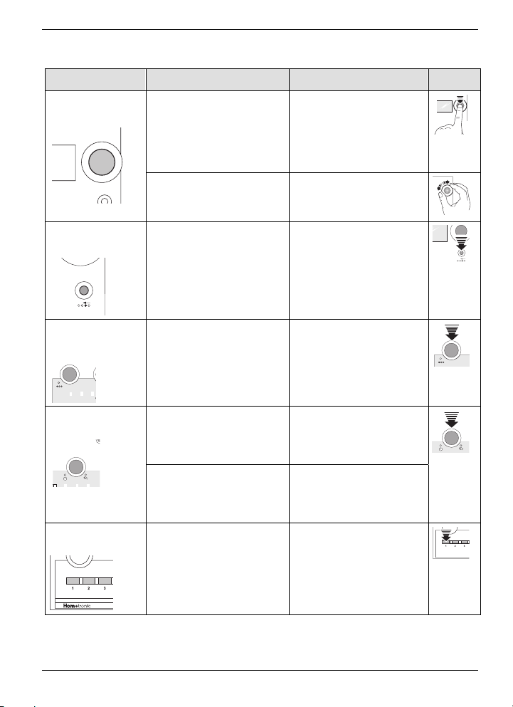
With ... You can: ... To do so you must:
►
... the
Dial button
• change to the main
menu
... press the Dial
button!
• call up submenus
and values
• confirm inputs
►
... turn the Dial
button (to the left or
right)!
►
... press the Back
button!
... the
Back button
• navigate through
menus
• change values
• move up one menu
level
• reject changes
(which you have
not confirmed)
... the
eco button
• change between
normal and econ-
►
... press the eco
button!
omy temperature
►
... the Auto/
Manual button
• change between
automatic and
manual mode
• deactivate an ac-
tive lifestyle
... press the
Auto/Manual but-
ton!
►
... press the
Auto/Manual but-
ton 2x!
... the Lifestyle
buttons
• activate a lifestyle
►
... press the Life-
style button!
Page 4

Hometronic – An Overview
Information on these instructions
Information on these instructions
Congratulations! With the Hometronic you have chosen a modern, comfortable home automation system.
Comfort, economy and security simply by pressing a button –
Hometronic ensures your well-being by simple means.
This brochure is intended to familiarize you with handling your
system, but can also be of use if any questions arise later.
Please keep it in a safe place!
Getting started
Fold out the left-hand cover, where the operating and display
elements are explained. Leave the cover folded out while reading
further.
The Section "Getting started" from Page 23 onwards familiarizes
you with the basic operation.
Specific search
You are already familiar with your Hometronic, but wish to look
up a specific topic?
• Technical terms are identified by an * and are explained in
the glossary from Page 116.
• Help on any problems can be found from Page 111 onwards.
Symbols used
In addition to the symbols for operating the Hometronic Manager
the following symbols are also used:
Information (depending on the configuration of your Hometronic)
Hint
For your information
Page 5
Hometronic – An Overview
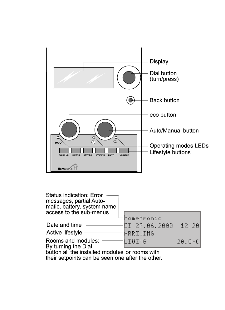
Display and operating elements
Display and operating elements
Display: The standard display
Page 6

Page 7

Contents
Contents
Information on these instructions II
Getting started II
Specific search II
Symbols used II
Display and operating elements III
Display: The standard display III
Hometronic – An Overview 6
Safety note 6
Software version 6
Hometronic: Living comfort with a system 7
Comfort: The home automation system 8
Cosiness: Heating and shading 8
Overview: Consumption metering 8
Safety: Presence simulation and wind protection 8
Important information on: Operating modes and
functions 9
Automatic mode 9
Lifestyle mode 10
eco mode (economy mode) 11
Partial automatic mode 12
Manual mode 12
Functions 12
Temperature control with HCM 200d and storey
controller 20
Boiler feedback 21
1
Page 8

Hometronic – An Overview
Display and operating elements
Operation 23
Getting started 23
Changing batteries 23
Setting date and time 24
Reading and noting the version number 25
Selecting operating modes 27
Activating Automatic mode 27
Activating Lifestyle mode 27
Activating eco mode (economy mode) 32
Activating partial Automatic mode 32
Activating Manual mode 33
Activating functions 34
Activating presence simulation 34
Activating sun protection function 35
Activating automatic brightness control 36
Activating wind protection 37
Disabling Hometronic Manager 37
Setting room parameters 37
Reading system values 39
Changing to "Display" submenu 39
Reading sensor values 40
Reading room temperature 40
Reading heating consumption 41
Reading consumption of a metering unit 42
Status display 43
Radiator controller HR 50 44
Setting radiator controller HR 50 44
Setting up remote access to HR 50 45
Remote access to radiator controller HR 50 45
2
Page 9

Contents
Room temperature sensor HCF 22 and setpoint adjuster
HCW 22 47
Installing HCW 22 or HCF 22 and assigning it to a
room 47
Removing assignment to a room 48
Thermostat control with boiler feedback 50
Installing collection relay 50
Uninstalling collection relay 51
Installing boiler relay 52
Deinstalling boiler relay 53
Adaptation 54
Saving and getting system settings 54
Changing to the "Settings" submenu 54
Saving system settings 55
Getting system setting 56
Adapting time programs 57
Changing to the "Time programs" submenu 57
Changing an entry 58
Deleting an entry 59
Deleting all entries 61
Inserting entries 62
Copying entries 64
Copying all entries 65
Adapting lifestyles 67
Changing to the "Lifestyles" submenu 67
Changing setpoints of a module or room 68
Deleting a module or a room from a lifestyle 69
Assigning a module or a room to a lifestyle 70
Assigning values to a free lifestyle 72
3
Page 10

Hometronic – An Overview
Display and operating elements
Adapting sun protection function of a shutter 73
Assigning a shutter to a sensor 73
Adapting opening width of a shutter 75
Adapting slat inclination 77
Setting temperature-dependent sun protection
(shading) of a shutter 78
Setting response delay of shutters 80
Adapting automatic brightness control 83
Assigning lamps to a brightness sensor 83
Changing brightness values (threshold values) 84
Adapting lamp brightness to brightness values 85
Adapting wind protection 87
Adapting thermostat control 88
Installing stages of thermostat control 88
Setting stages of thermostat control 90
De-installing stages of thermostat control 91
Temperature control via sensor/contact switch 93
Assigning room to a sensor 93
Adapting setpoint of a sensor 95
Reading setpoint of a sensor 96
Adapting daylight saving time 97
Adapting basic system settings (parameters) 99
Changing to the "Parameters" submenu 99
Adapting a parameter 100
Changing names 101
Changing to the "Change name" submenu 101
Renaming lifestyles, modules and rooms 101
4
Page 11

Contents
Appendix 103
Factory settings 103
Lifestyles 103
Time programs (entries) 104
Basic system settings (parameters) 104
Sun protection (shading) function 106
Wind function 107
Possible metering unit types and corresponding units 107
Settings and ranges 108
Temperatures 108
Illumination 108
Shutter 108
Devices 108
Tables with your configuration 109
Lifestyles 109
Time programs 110
Help with problems 111
Error messages in display 111
Faults 113
Service mode (for installers only) 114
Glossary 116
Overview of Hometronic modules 119
Index 121
Notes 126
5
Page 12
Hometronic – An Overview
HOMETRONIC – AN OVERVIEW
Safety note
Moisture in the Hometronic Manager!
Moisture which seeps into the device can cause permanent
Caution!
Software version
damage.
►
Install the Hometronic Manager in dry, closed rooms only.
To make use of the functions described in these instructions, you
will require software version 6.00 or greater for the HCM 200d.
If you are currently using a lower version in the HCM 200d,
please contact your installer regarding an update or device replacement.
For further information please refer to Chapter "Reading and
noting the version number" from Page 25 onwards.
6
Page 13
Hometronic – An Overview
Hometronic: Living comfort with a system
Hometronic: Living comfort with a system
6
5
4
3
2
1
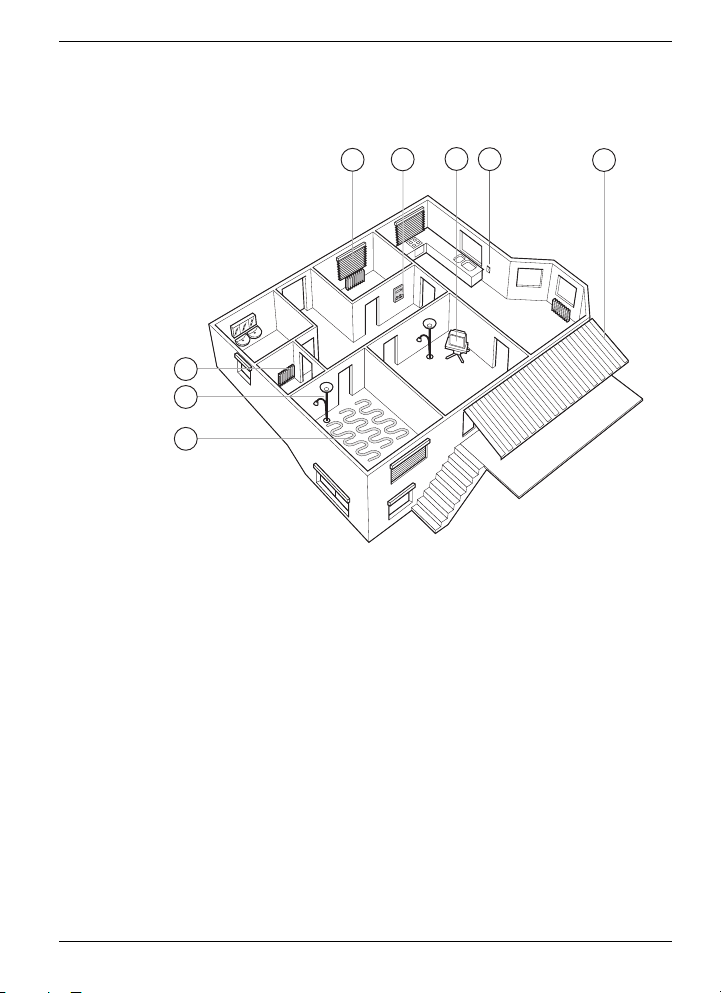
Hometronic is the name of the modular home automation system
from Honeywell. The Hometronic consists of a number of individual components*:
• The Hometronic Manager, installed at a central position (5)
in your home.
• The Hometronic modules, connected wirelessly to the
Hometronic Manager, are used to dim lamps (2), control
shutters, blinds (4) or awnings (8), switch devices (6) etc.
• The heating system with controllers for radiator valves (3)
or floor heating (1), temperature sensors or controllers (7) for
specific controlling of the room temperature in different
rooms.
• Additional sensors for measuring the consumption.
7
8
7
Page 14

Hometronic – An Overview
Hometronic: Living comfort with a system
Comfort: The home automation system
Hometronic modules offer a multitude of automatic control possibilities. You can ...
• Dim and switch lights
• Open or close shutters or blinds
• Switch electrical devices on and off.
You can also carry out every function manually.
Cosiness: Heating and shading
You can control the room temperature at the Hometronic Manager and heat individual areas of the home individually.
The sun protection function controls shutters and awnings and
protects your furnishings against strong sun irradiation. Shutters
may be controlled on a light or temperature basis.
Overview: Consumption metering
Hometronic detects and saves the consumption of heat and cold
and hot water. The consumption values are displayed at the
Hometronic Manager.
Safety: Presence simulation and wind protection
Lamps and devices repeat the switching processes of the past
days. Your home appears to be occupied even when you are
away.
Wind sensors automatically protect awnings and shutters at high
wind forces.
8
Page 15

Hometronic – An Overview
Important information on: Operating modes and functions
Important information on: Operating modes and
functions
How is an operating mode displayed? How do you activate an
operating mode? Read Chapter "Selecting operating modes"
from Page 27 onwards.
Operating possibilities
Irrespective of the active operating mode you can always ...
• ... directly operate a device, shutter or heating manually
• ... change a setpoint manually by using the Hometronic
Manager.
Automatic mode
Automatic mode is the standard operating mode of the Hometronic Manager. In automatic mode the heating, shutters and
lamps/devices are controlled via time programs.
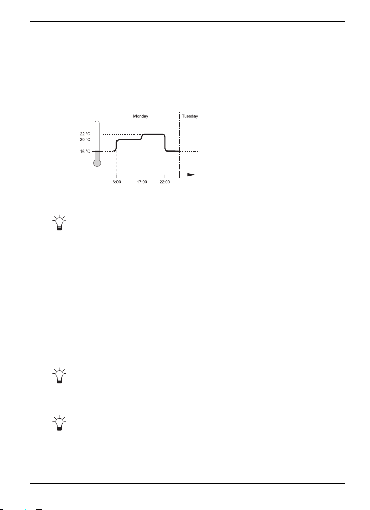
A time program...
... consists of a sequence of setpoints and corresponding switching points. You specify a time program for every module or every
room.
A setpoint...
... is a value which stipulates a specification, e.g. which temperature is to rule in a room. If the setpoint temperature is e.g. specified as 21 °C, the Hometronic regulates the room temperature to
this value.
Setpoints can be changed manually at any time. This change is
in effect until the next switching point.
Additional setpoints are, e.g.
• Brightness of a lamp
• Opening width and slat inclination of a shutter.
9
Page 16
Hometronic – An Overview
Important information on: Operating modes and functions
A switching point...
... is a moment at which a device is to be controlled by the
Hometronic Manager. If, for example, a shutter is to be opened at
7 a.m., 7:00 is the switching point.
Example: The time program of a heating
Switching point Setpoint
at 6:00 a.m. 20 °C
at 5:00 p.m. 22 °C
at 10:00 a.m. 16 °C
Factory settings
The Hometronic Manager is already equipped with time programs from the factory. The appendix contains a table of these
time programs from Page 104 onwards.
Lifestyle mode
Lifestyles contain an individually adaptable number of setpoints,
which control various devices and modules at a specified time.
When you activate a lifestyle, these setpoints become active.
Example: You go on holiday and activate the "Vacation" lifestyle.
• The room temperature of your home is regulated to 15 °C.
• Shutters are controlled by the sun protection function*.
• Lamps are controlled in the presence simulation.
The lifestyles can be reset by pressing the Auto/Manual button
twice.
Predefined lifestyles
6 lifestyles are preset in our factory (refer to the appendix
Page 103). Up to 16 lifestyles are possible.
10
Page 17
Hometronic – An Overview
Important information on: Operating modes and functions
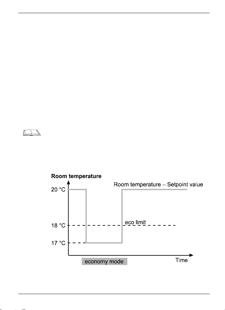
eco mode (economy mode)
In eco mode* the setpoint temperature is lowered to a specified
value (eco lowering value) in all the rooms.
Room temperature setpoint, eco lowering value and eco limit
If the setpoint temperature of a room (room temperature setpoint)
is above the eco limit, it is lowered by the eco lowering value.
If the setpoint temperature is below the eco limit, it remains outside eco mode.
Values for the eco lowering value and eco limit are set in the
basic system settings in the factory, and room temperature setpoints are specified in the time programs (see appendix, from
Page 104 onwards).
For information on changing the basic system settings, refer to
Chapter "Adapting basic system settings (parameters)" from
Page 99 onwards. For information on creating, deleting or changing the time programs, read the Chapter "Adapting time programs" from Page 57 onwards.
Example:
11
Page 18

Hometronic – An Overview
Important information on: Operating modes and functions
The following values are set:
• Room temperature setpoint 20 °C
• eco lowering value 3 °C
• eco limit 18 °C
In eco mode, the room temperature is lowered from 20 °C to
17 °C.
If the eco limit is set to 21 °C for example, the room temperature
does not change with the same setpoint of 20 °C in eco mode.
Partial automatic mode
You can specify individually for the heating/cooling (H), shutters
(R) and lamps/devices (L) whether they are to be operated
manually or automatically.
Manual mode
In manual mode* all the automatic functions (time programs, sun
protection function, presence simulation, automatic brightness
control and others) are deactivated. The setpoints valid when the
operating mode was changed remain valid.
Functions
12
Presence simulation
Light and device switches simulate the switching processes of
the last 7 days. This function remains valid until a setpoint overwrites the presence simulation.
Recording for the simulation is carried out automatically.
Wind protection
This function remains active as long as a wind sensor measures
high wind speeds in order to protect shutters or awnings against
damage through storms. These shutters or awnings cannot be
operated manually during this function.
Page 19
Hometronic – An Overview
Important information on: Operating modes and functions
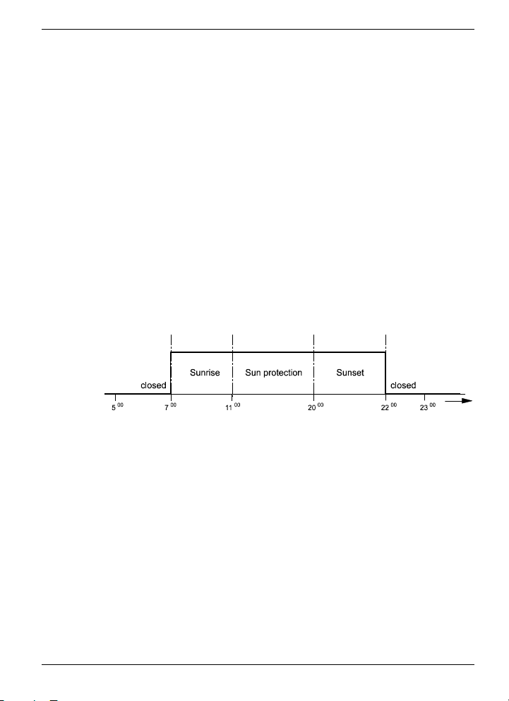
Sunrise, sunset, shading
A brightness sensor controls the position of shutters or awnings
within a specified time window (e.g. from switching time sunrise
to switch time shading), regardless of the measured brightness
level.
The functions sunrise, sunset and sun protection are activated
manually, via time programs or lifestyles and are controlled by 3
values:
• Brightness value
• Switching time
• Setpoint position
The response time of the shutters can be delayed (see "Setting
response delay of shutters" on Page 80).
The sun protection function can also be controlled by the outside
or inside temperature (see "Sun protection function (SP)" on
Page 14).
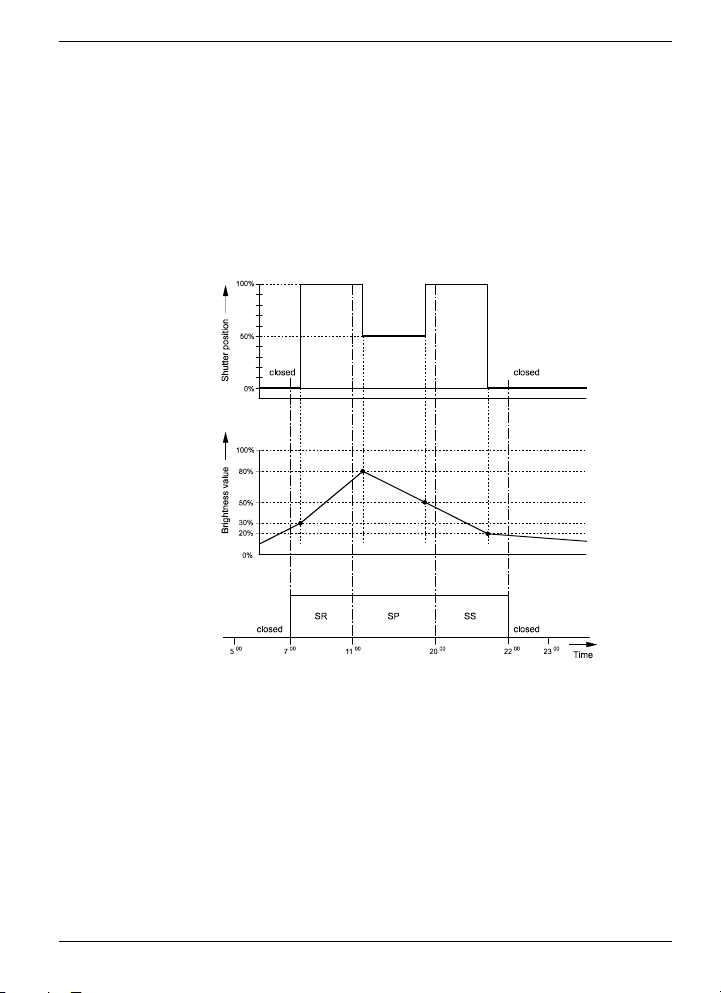
Sunrise function (SR)
Shutters are moved to the setpoint position when the switching
time and brightness value are reached.
Example:
Shutters are opened up to 80 % in the morning starting at
7.00 a.m. if 30 % of the brightness value is reached.
The shutters remain closed if the brightness value is not reached.
They are opened to 80 % when the brightness level is reached. If
the shutters are already above the setpoint (e.g. due to manual
setting to 90 % on the previous evening), they are not moved.
Sunset function (SS)
Shutters are moved to the setpoint position when the switching
time and brightness value are reached. If the shutters are already below the setpoint position, they are not moved.
13
Page 20

Hometronic – An Overview
Important information on: Operating modes and functions
Sun protection function (SP)
The position of the shutters depends on the measured brightness
level. The sun protection function is activated via time programs,
lifestyles or manually. Shutters move to the setpoint position if
sun protection is active and the brighness value is reached. The
sun protection function can also be activated/deactivated on a
temperature basis (see the next page).
The following values are required:
• Switching point for start of shading, e.g. 11:00 a.m.
• Two brightness values for start and end of shading,
e.g. 80 % and 50 %
• Setpoint position of shutters for shading, e.g. 50 %
14
Page 21
Hometronic – An Overview
Important information on: Operating modes and functions
Example:
The shutters are in the OPEN position. Sun protection is to be
activated from 11:00 a.m. on, i.e. if 80 % of the brightness value
has been reached, the shutters move to the setpoint position of
50 %. If the brightness value of 50 % is not reached, the shutters
move to the starting position (OPEN) again. If the brightness
value rises above 80 % again, sun protection is reactivated.
15
Page 22
Hometronic – An Overview
Important information on: Operating modes and functions
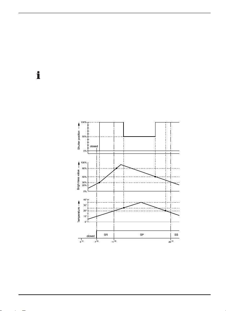
Temperature-dependent sun protection function
The sun protection function is activated and deactivated depending on the inside or outside temperature. If the sun protection
function is active, shutters are moved to the setpoint position
when the switching time and brightness level are reached.
The temperature-dependent control of shutters occurs solely
during shading, and not during sunrise or sunset.
The following values are also required for temperaturedependent shading:
• Inside temperature for sun protection activation, e.g. 25 °C
• Inside temperature for sun protection deactivation, e.g. 20 °C
16
Example:
Sun protection is to be activated from 11:00 a.m. If 80 % of the
brightness level has been reached, the inside temperature is still
under 25 °C. Sun protection is not activated and the shutters
remain open.
Page 23

Hometronic – An Overview
Important information on: Operating modes and functions
If the temperature reaches 25 °C, the sun protection function is
reached and the shutters close to 50 %. If the brightness value
undershoots 50 %, the shutters move to the starting position
(OPEN) again.
If the outside temperature drops below 20 °C, sun protection is
deactivated, regardless of the brightness value. The shutters
then remain in their current position.
For information on adapting the setpoint for the functions described above, please read the Chapter entitled "Setting temperature-dependent sun protection (shading) of a shutter" from
Page 78 onwards.
If outside and inside temperature sensors are installed for this
function, sun protection is deactivated if the inside and outside
temperatures are below the threshold values. Sun protection is
activated as soon as one of the 2 temperatures exceeds the
corresponding threshold value.
Remote access to radiator controller HR 50
To control the radiator controller HR 50 via a setpoint adjuster
HCW 22 or a temperature sensor HCF 22, the devices must be
assigned to the same room at the Hometronic Manager
HCM 200d.
The HCM 200d displays the room temperature of the HCW 22
here. The temperature offset is displayed by an arrow in the
menu:
• Arrow up = plus
• Arrow down = minus
• No arrow = offset 0
If a temperature sensor HCF 22 is installed, only the room temperature without the offset is sent to the Hometronic Manager.
For information on setting the radiator controller HR 50, please
read the Chapter entitled "Activating Manual mode " from Page
33 onwards.
17
Page 24
Hometronic – An Overview
Important information on: Operating modes and functions
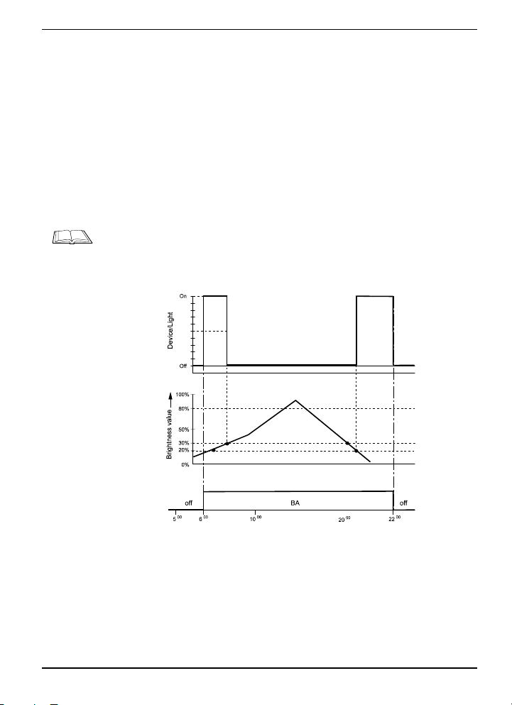
Automatic brightness control (BA)
You control the light in the building or in the outside area via a
brightness sensor. The following values are required for this:
• Lower automatic threshold value, e.g. 20 %
• Upper automatic threshold value, e.g. 30 %
• Lower illumination value, e.g. ON
• Upper illumination value, e.g. OFF
For information on adapting the setpoint for the function described above, please read the Chapter entitled "Adapting automatic brightness control" from Page 83 onwards.
18
Example:
From 6:00 a.m. on, the light (device) is to be switched on and off
automatically. If the brightness value is under 20 %, the light
(device) switches on. The light (device) switches off if the brightness value reaches 30 %.
Page 25
Hometronic – An Overview
Important information on: Operating modes and functions
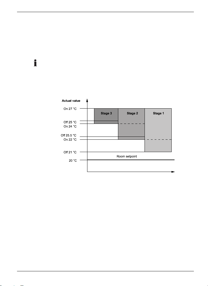
Thermostat control
You cool and heat a room depending on the room temperature
via the thermostat control function. You can activate any actuator
(electric heater, zone control, fan etc.).
The temperature difference (offset) between the stages is to be
at least 2 °C. The setting ranges of the offset are +/–10 °C.
The following values are also required for thermostat control:
• Room setpoint, including offset, e.g. 20 °C
• Temperature offsets of the individual stages
Example:
A room is to be cooled with a fan (with 3 stages). The room set-
point is 20 °C. Stage 1 is activated when the room temperature is
22 °C. If the room temperature of 21 °C is exceeded, Stage 1 is
deactivated. If the room temperature rises above 27 °C, stages 1,
2 and 3 are activated.
Disable function (child-proofing)
You can disable the Hometronic Manager or radiator controllers.
Manual changes cannot be carried out during the disable function. Setpoints of the time program or values entered at the
Hometronic Manager continue to be transferred.
19
Page 26
Hometronic – An Overview
Important information on: Operating modes and functions
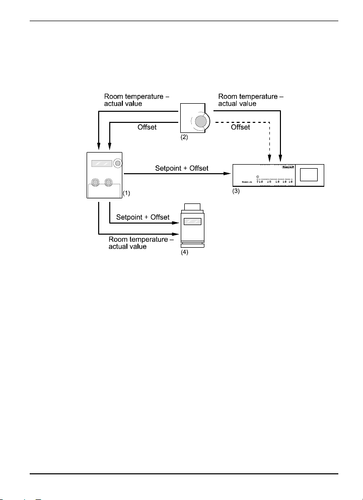
Temperature control with HCM 200d and storey controller
A setpoint adjuster HCW 22 is assigned to the HCM 200d and to
a storey controller HCE for the same room.
(1) Hometronic Manager HCM 200d
(2) Setpoint adjuster HCW 22
(3) Storey controller HCE 60
(4) Radiator controller HR 50
Example:
1. A setpoint of 20 °C is specified in the HCM 200d. The setpoint adjuster measures a current temperature of 18 °C. Furthermore, an offset of +3 °C is set at the adjustment dial.
2. The setpoint adjuster transmits the current temperature
(18 °C) and the offset (+3 °C) to the storey controller and the
HCM 200d.
3. The HCM 200d transmits...
• the current temperature (18 °C) and the sum of the set-
point and the offset (23 °C) to the radiator controller,
• the current temperature (18 °C) and the sum of the set-
point and the offset (23 °C) to the radiator controller.
20
Page 27

Hometronic – An Overview
Important information on: Operating modes and functions
In order that the offset is not taken into account twice, the storey
controller ignores the offset from the setpoint adjuster (dotted
line).
Storey controller and radiator controller regulate the temperature
to 23 °C.
Boiler feedback
Boiler feedback can occur via a setpoint or as needed via the
valve position of all installed HR 80s.
Boiler feedback set HK 10 (room setpoint-based)
The boiler feedback set HK 10 can be used for feedback to the
heat generation. The boiler feedback set consists of the room
temperature sensor HCF 22 and the device switch HS 20/30 (as
a collection relay).
The Hometronic Manager sends a request signal to the collection
relay HS 20/30 at a set boiler setpoint. The selectable boiler
setpoint (18 °C is preset) is specified in the Parameters menu
item of the HCM 200d. The boiler setpoint is constantly compared with the room setpoint temperatures of the installed zones.
The collection relay HS 20/30 is switched on as soon as the room
setpoint temperature of a zone exceeds the boiler setpoint. The
collection relay is deactivated again if all of the room setpoint
temperatures are below the boiler setpoint.
The room temperature sensor HCF 22 is used for the anti-freeze
function. The anti-freeze temperature can also be set via the
Parameters menu item.
See also Chapter "Installing collection relay" on Page 50.
Thermostat control with boiler feedback via HS 20/30
A device switch HS 20/30 can be used (as a collection relay) for
feedback of the heat generation with thermostat control. The
collection relay switches the boiler on as soon as a relay in a
zone under thermostat control is activated.
For information on installing and setting the thermostat controller,
read from Page 88 onwards.
21
Page 28
Hometronic – An Overview
Important information on: Operating modes and functions
Installation of the collection relay (HS 20/30) has no effect on the
maximum number of devices at the Hometronic Manager HCM
200d.
Thermostat control with boiler feedback via HR 80 and
HC60NG (valve position-based)
With need-based boiler feedback, all HR 80s send information on
their valve position to the Hometronic Manager. When necessary,
the Hometronic Manager sends the boiler request to relay
HC60NG, which switches the boiler on.
See also Chapter "Installing boiler relay" on Page 52.
Analog output (TW)
The Hometronic Manager can be connected to a Honeywell
controller (MCR 35/40/200 or Panter) and regulate the heat generator as needed. The connection diagram can be found in the
installation instructions of the Hometronic Manager.
Regulation of the heat generator occurs depending on either the
room setpoints or the valve position.
The following parameters must be set for this:
Analog output (TW) Setpoint
Dependent on valve position
(only with HR 80)
Dependent on room setpoint ON
OFF (default setting)
22
Page 29
Operation
Getting started
OPERATION
Getting started
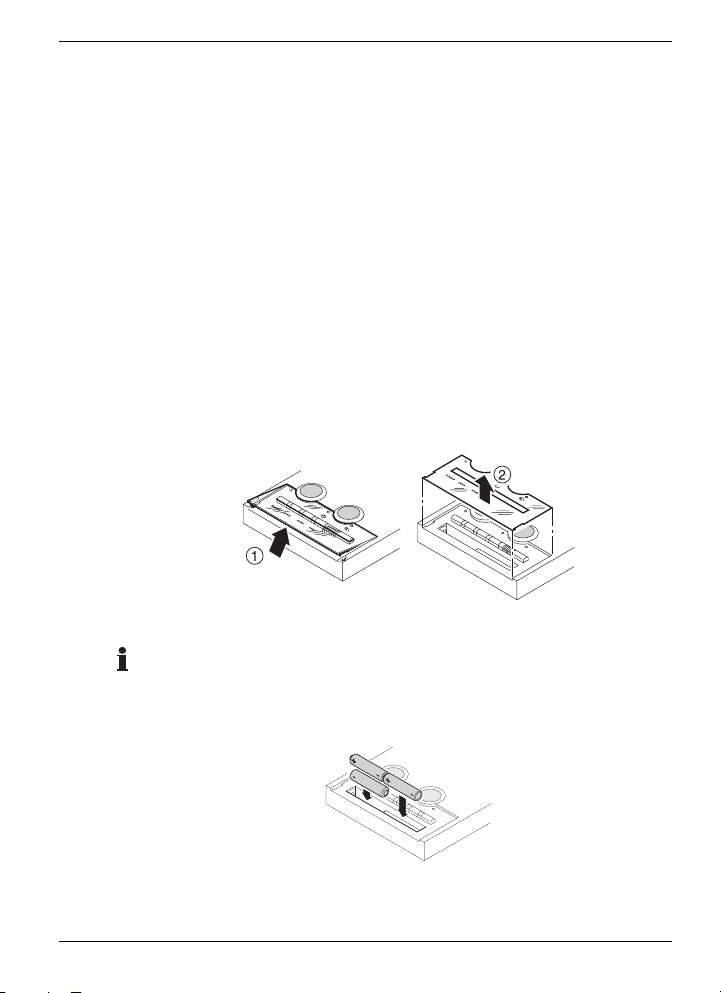
Changing batteries
The batteries must be changed as soon as the ! symbol appears
in the display and the Hometronic Manager is displayed with the
battery symbol in the status display (see Chapter "Status display"
on Page 43).
Only use the following button batteries*:
• Alkali manganese LR03 (lifespan approx. 2 years) or
• 1.5 V rechargeable: LR03 (lifespan approx. 3/4 year)
►
Remove the transparent plastic cover (1) over the Lifestyle
buttons and the white lifestyle foil (2).
►
Use a small screwdriver to remove the old batteries.
Always replace all 3 batteries at the same time. Ensure that the
polarity is correct!
►
Insert the new batteries.
►
Replace the white lifestyle foil and the plastic cover again.
The Hometronic Manager is ready to operate.
23
Page 30
Operation
Getting started
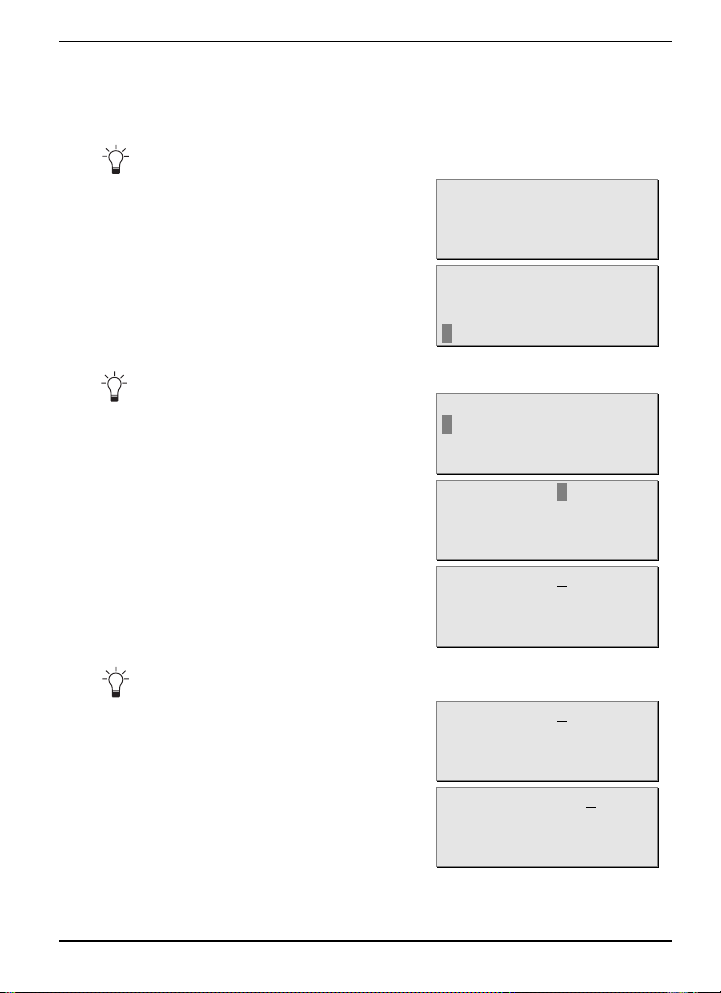
Setting date and time
You can abort the settings any time by pressing the Back button.
►
Press the Back button repeatedly until the standard display
is shown, for example:
►
Press the Dial button.
A flashing rectangle is displayed on the bottom line:
If the cursor flashes over a value, it is selected.
►
Turn the Dial button until "Set
date/time" is selected.
►
Press the Dial button.
The following text is displayed:
►
Press the Dial button again.
The following text is displayed:
An underlined value can be changed by turning the Dial button.
►
Turn the Dial button until the
current date is displayed, for
example:
►
Press the Dial button twice.
The following text is displayed:
Hometronic
Please check time
No Lifestyle active
LIVING 20.0 C
MENU
SET DATE/TIME
ACTIVATE LIFESTYLE
LIVING 20.0 C
MENU
SET DATE/TIME
ACTIVATE LIFESTYLE
LIVING 20.0 C
Date: 29.10.2001
Time: 11:15
Date: 29.10.2001
Time: 11:15
Date: 04.10.2001
Time: 11:15
Date: 04.10.2001
Time: 11:15
24
Page 31

Operation
Getting started
►
Turn the Dial button until the
current month is displayed, for
example:
►
Press the Dial button twice.
The following text is displayed:
►
Turn the Dial button until the
current year is displayed, for
example:
►
Change the hour and minutes by the same method.
►
When the current date and the right time are displayed, press
Date: 04.11.2001
Time: 11:15
Date: 04.11.2001
Time: 11:15
Date: 04.11.2003
Time: 11:15
the Dial button in order to save the date and the time.
►
Press the Back button.
The standard display is displayed.
Hometronic
SU 04.11.2003 12:16
No Lifestyle active
LIVING 20.0 C
The date and time are set.
Reading and noting the version number
The display shows the standard
display, for example:
►
Press the Dial button.
The cursor flashes on the bottom line.
►
Turn the Dial button to the right
until the cursor flashes on the
highest line.
Hometronic
SU 04.11.2001 12:16
No Lifestyle active
LIVING 20.0 C
MENU
SET DATE/TIME
ACTIVATE LIFESTYLE
LIVING 20.0 C
MENU
SET DATE/TIME
ACTIVATE LIFESTYLE
LIVING 20.0 C
25
Page 32

Operation
Getting started
►
►
►
These data are required for servicing.
►
Version number table
►
Press the Dial button.
The following text is displayed:
LIFESTYLES
TIME PROGRAMS
DISPLAY
SETTINGS
Turn the Dial button to the left
until "Version" is selected:
TIME PROGRAMS
DISPLAY
SETTINGS
VERSION
Press the Dial button.
The following text, for example,
is displayed:
HCM200d P2 V6.00 UK
04.Aug.2004 13:00
433 V 13 868 V A1
Device No. 01-003290
Note the data shown in the display in the table below.
Press the Back button in order to leave the submenu.
26
Page 33

Operation
Selecting operating modes
Selecting operating modes
Activating Automatic mode
►
Press the Auto/Manual button as often as required until
the LED
The Hometronic is in automatic mode.
For information on adapting the time programs to your requirements, read the Chapter "Adapting time programs" from Page 57
onwards.
Activating Lifestyle mode
You can activate or program a lifestyle at any time irrespective of
the current operating mode. The method for selecting the lifestyle
depends on whether or not it is assigned to a Lifestyle button.
The "Vacation" lifestyle is selected in the following examples.
Proceed in a similar manner in order to select another lifestyle.
After a lifestyle has been selected, it can be started immediately
or with a timer or be programmed to start in the future.
Selecting the "Vacation" lifestyle with the Lifestyle button
►
Press the "Vacation" Lifestyle
button.
The following text is displayed:
The "Vacation" lifestyle is selected and can be activated or programmed.
►
For additional information, see "Activating a lifestyle".
Selecting a lifestyle via the menu
The display shows the standard
display, for example:
►
Press the Dial button.
The following text is displayed:
lights up.
VACATION
From active immediat
To
OK
Hometronic
WE 29.09.2002 11:15
No Lifestyle active
HEATING/COOLING AUTO
MENU
SET DATE/TIME
ACTIVATE LIFESTYLE
HEATING/COOLING AUTO
27
Page 34

Operation
Selecting operating modes
►
Turn the Dial button to the right
until "Activate lifestyle" is selected.
►
Press the Dial button.
The names of the lifestyles are
displayed.
►
Turn the Dial button until the
desired lifestyle is selected, for
example:
►
Press the Dial button.
The following text is displayed:
MENU
SET DATE/TIME
ACTIVATE LIFESTYLE
HEATING/COOLING AUTO
ACTIVATE LIFESTYLE
WAKE UP
LEAVING
ARRIVING
ACTIVATE LIFESTYLE
VACATION
LIFESTYLE 7
LIFESTYLE 8
VACATION
From active immediat
To
OK
The "Vacation" lifestyle is selected and can be activated or programmed.
Activating a lifestyle
If you activate a lifestyle immediately without a time limit, its setpoints only remain valid until they are overwritten by the time
program.
►
Select the "Vacation" lifestyle as described on Page 27.
The following text is displayed:
VACATION
From active immediat
To
►
Press the Dial button.
The following text, for example,
is displayed:
OK
Hometronic
WE 29.09.2002 11:15
VACATION
HEATING/COOLING AUTO
The "Vacation" lifestyle is active without timer function.
28
Page 35

Operation
Selecting operating modes
Activating lifestyle with timer immediately
►
Select the "Vacation" lifestyle as described on Page 27.
The following text is displayed:
VACATION
From active immediat
To
►
Turn the Dial button to the right
until "To" is selected.
OK
VACATION
From active immediat
To
►
Press the Dial button.
The current date appears in the
display:
►
Turn the Dial button to the right
until the day is selected on the
"To" line.
►
Press the Dial button.
The following text is displayed:
OK
VACATION
From 17.01.2002 15:22
To 17.01.2002 15:22
DELETE OK
VACATION
From 17.01.2002 15:22
To 17.01.2002 15:22
DELETE OK
VACATION
From 17.01.2002 15:22
To 17.01.2002 15:22
DELETE OK
►
Turn the Dial button until the desired day is displayed.
►
Adapt the month, year and time in a similar manner.
►
Turn the Dial button until "OK"
is selected.
►
Press the Dial button.
The following text is displayed:
The "Vacation" lifestyle is active with timer function.
VACATION
From 17.01.2002 15:22
To 27.01.2002 17:50
DELETE OK
Hometronic
WE 17.01.2002 15:23
VACATION
HEATING/COOLING AUTO
29
Page 36

Operation
Selecting operating modes
Programming lifestyle to start in the future
►
Select the "Vacation" lifestyle as described on Page 27.
The following text is displayed:
►
Turn the Dial button to the right
until "From" is selected.
►
Press the Dial button.
The current date appears in the
display:
►
Press the Dial button again.
The following text is displayed:
►
Turn the Dial button until the
desired day is displayed.
►
Press the Dial button.
The following text is displayed:
►
Adapt the month, year and time in a similar manner.
►
Change the date and time for the end time under "To".
►
Turn the Dial button until "OK"
is selected.
►
Press the Dial button.
The following text is displayed:
VACATION
From active immediat
To
OK
VACATION
From active immediat
To
OK
VACATION
From 17.01.2002 15:22
To 17.01.2002 15:22
DELETE OK
VACATION
From 17.01.2002 15:22
To 17.01.2002 15:22
DELETE OK
VACATION
From 18.01.2002 15:22
To 17.01.2002 15:22
DELETE OK
VACATION
From 18.01.2002 15:22
To 17.01.2002 15:22
DELETE OK
VACATION
From 18.01.2002 07:30
To 25.01.2002 17:30
DELETE OK
TH 17.01.2002 15:23
No Lifestyle active
HEATING/COOLING AUTO
30
Page 37

Operation
Selecting operating modes
The "Vacation" lifestyle is programmed and then activated and deactivated
again at the programmed times with the timer function.
Only one lifestyle is active, even if several lifestyles are programmed. With a sequence of several lifestyles, the last started
lifestyle is always active.
Deleting timer parameters for Lifestyle mode
The display shows the standard
display, with activated timer function for example:
►
Select the "Vacation" lifestyle
as described on Page 27.
The lifestyle is identified by a
clock in the display:
►
Press the Dial button.
The following text is displayed:
►
Turn the Dial button until "Delete" is selected.
TH 17.01.2002 15:23
No Lifestyle active
HEATING/COOLING AUTO
ACTIVATE LIFESTYLE
EVENING
PARTY
VACATION
VACATION
From 18.01.2002 07:30
To 25.01.2002 17:30
DELETE OK
VACATION
From 18.01.2002 07:30
To 25.01.2002 17:30
►
Press the Dial button.
The following text is displayed:
DELETE OK
Hometronic
TH 17.01.2002 15:23
No Lifestyle active
HEATING/COOLING AUTO
The timer parameters for the "Vacation" lifestyle are deleted.
Deactivating lifestyle
►
Press the Auto/Manual button
twice.
The following text is displayed:
Hometronic
WE 29.09.2002 11:15
No Lifestyle active
HEATING/COOLING AUTO
The lifestyle is deactivated.
31
Page 38

Operation
Selecting operating modes
Activating eco mode (economy mode)
►
Press the eco button.
The eco LED lights up green. Hometronic is in eco mode.
Deactivating eco mode
►
Press the eco button again.
The eco LED is extinguished. The eco mode is deactivated.
Activating partial Automatic mode
Example: Changing the devices/lights area to manual mode.
The display shows the standard
display, for example:
►
Turn the Dial button to the left
until "Devices/lights" is displayed on the bottom line.
►
Press the Dial button twice.
The following text is displayed:
►
Turn the Dial button until
"Manu" is displayed.
►
Press the Dial button twice.
The following text is displayed:
The devices/light area is changed over to manual mode. The heating and
shutters continue to be controlled in automatic mode.
Hometronic
WE 29.09.2002 11:15
No Lifestyle active
LIVING 20.0 C
Hometronic
WE 29.09.2002 11:15
No Lifestyle active
DEVICES/LIGHTS AUTO
Change value:
DEVICES/LIGHTS AUTO
OK
Change value:
DEVICES/LIGHTS MANU
OK
MANU- L
WE 29.09.2002 11:15
No Lifestyle active
DEVICES/LIGHTS MANU
32
Page 39

Operation
Selecting operating modes
Activating Manual mode
►
Press the Auto/Manual button as often as required until the
LED lights up red.
"MANU-HSL" is displayed in the
top right of the display.
The Hometronic is in Manual mode.
All the current setpoints, whether set manually or of the active
time program are retained.
Changing setpoints
Example: Changing the living room lamp brightness.
The display shows the standard
display, for example:
►
Turn the Dial button until the
desired module is displayed, for
example:
►
Press the Dial button twice.
The following text is displayed:
►
Turn the Dial button until the
desired value is displayed, for
example:
►
Press the Dial button twice.
The following text is displayed:
The brightness of the living room lamp has been changed.
MANU-HSL
WE 29.09.2002 11:15
No Lifestyle active
LIVING 20.0 C
MANU-HSL
WE 29.10.2000 11:15
No Lifestyle active
SHUTT LIV 10%
MANU-HSL
WE 29.10.2000 11:15
No Lifestyle active
LIVING LAMP 70%
Change value:
LIVING LAMP 70%
OK
Change value:
LIVING LAMP 50%
OK
MANU-HSL
WE 29.10.2000 11:15
No Lifestyle active
LIVING LAMP 50%
33
Page 40

Operation
Activating functions
Activating functions
Activating presence simulation
Example: Activating the presence simulation at the living room
lamp.
The display shows the standard
display, for example:
►
Turn the Dial button until the
desired module is displayed on
the bottom line, for example:
►
Press the Dial button twice.
The following text is displayed:
►
Turn the Dial button to the left
until "PS" is displayed:
►
Press the Dial button twice.
The following text is displayed:
The living room lamp repeats the switching processes of the last 7 days.
Hometronic
WE 29.09.2002 11:15
No Lifestyle active
LIVING 20.0 C
Hometronic
WE 29.09.2002 11:15
No Lifestyle active
LIVING LAMP1 60%
Change value:
LIVING LAMP1 60%
OK
Change value:
LIVING LAMP1 PS
OK
Hometronic
WE 29.09.2002 11:15
No Lifestyle active
LIVING LAMP1 PS
34
For information on how to combine several modules for presence
simulation to a lifestyle, read the Chapter "Adapting lifestyles"
from Page 67.
Page 41

Operation
Activating functions
Activating sun protection function
Example: Activating the sun protection function of the living room
shutters.
The display shows the standard
display, for example:
►
Turn the Dial button until the
desired shutters are displayed
on the bottom line, for example:
►
Press the Dial button twice.
The following text is displayed:
►
Turn the Dial button to the left
until "SP" is displayed:
►
Press the Dial button twice.
The following text is displayed:
If a brightness sensor is installed and assigned to the living room shutters, it
is controlled according to the setpoints and switching points of the sun
protection function.
Hometronic
WE 29.09.2002 11:15
No Lifestyle active
LIVING 20.0 C
Hometronic
WE 29.09.2002 11:15
No Lifestyle active
SHUTT LIV OPEN
Change value:
SHUTT LIV OPEN
OK
Change value:
SHUTT LIV SP
OK
Hometronic
WE 29.09.2002 11:15
No Lifestyle active
SHUTT LIV SP
For information on assigning a sensor (brightness or temperature) to shutters and changing setpoints for the sun protection
function, please read in the Chapter "Adapting sun protection
function of a shutter" from Page 73 onwards.
You can activate/deactivate the sun protection function based on
temperature (see Chapter "Setting temperature-dependent sun
protection (shading) of a shutter" on Page 78).
35
Page 42

Operation
Activating functions
Activating automatic brightness control
The display shows the standard
display, for example:
Hometronic
WE 29.09.2002 11:15
No Lifestyle active
►
Turn the Dial button until the
desired brightness sensor is
displayed on the bottom line,
for example:
►
Press the Dial button twice.
The following text is displayed:
►
Turn the Dial button to the left
until "BA" is displayed.
►
Press the Dial button twice.
The following text is displayed:
LIVING 20.0 C
Hometronic
WE 29.09.2002 11:15
No Lifestyle active
BRIGHT SOUTH OFF
Change value:
BRIGHT SOUTH OFF
OK
Change value:
BRIGHT SOUTH BA
OK
Hometronic
WE 29.09.2002 11:15
No Lifestyle active
BRIGHT SOUTH BA
If a brightness sensor is installed and assigned to lights/devices, these
lights/devices are controlled according to the setpoints and switching points
of the automatic brightness control.
For information on assigning lamps to a sensor and on changing
setpoints for the automatic brightness control, please read the
Chapter entitled "Adapting automatic brightness control" from
Page 83 onwards.
36
Page 43

Operation
Activating functions
Activating wind protection
If a wind sensor is installed and assigned to the shutter, the wind
protection is activated automatically as soon as the wind speed
exceeds the set wind threshold.
For information on how to adapt this threshold, read the Chapter
"Adapting wind protection" on Page 87.
Disabling Hometronic Manager
►
Keep the Back button pressed
and press the Dial button
briefly simultaneously.
A key symbol is displayed in
the standard display.
The Hometronic Manager is in disabled mode.
Reversing disabling at the Hometronic Manager
►
Keep the Back button pressed and press the Dial button
briefly simultaneously.
The key symbol disappears. Disabling is reversed.
Setting room parameters
With the room parameters, you can disable radiator controllers,
activate the window function, activate the optimization function
and limit the setpoint range. The functions can be reversed here
as well. The parameters can be changed for all rooms or individual rooms. With the HR 50, only the disable function for all rooms
is available.
The values of the room parameters are found in Chapter "Basic
system settings (parameters)" on Page 104.
Example: Limit setpoint range for radiator controller HR 80.
37
Page 44

Operation
Activating functions
►
Switch to the "Settings" submenu as described on Page 54.
►
Turn the Dial button to the left
until "Room parameters" is selected.
►
Press the Dial button.
The following text is displayed:
►
Turn the Dial button to the left
until the room, whose parameter is to be set, is selected.
►
Press the Dial button.
The following text is displayed:
►
Turn the Dial button until the
parameter is selected.
The following text is displayed:
►
Press the Dial button.
The following text is displayed:
►
Turn the Dial button until the
desired value is displayed, for
example:
►
Press the Dial button.
The parameter has been changed.
ALARM PARAMETERS
CHANGE NAMES
CONFIGURATION
ROOM PARAMETERS
CHANGE ALL ROOM PAR.
LIVING
KITCHEN
SLEEPING
CHANGE ALL ROOM PAR.
LIVING
KITCHEN
SLEEPING
KITCHEN
Local oper. lock OFF
Optimization OFF
Window function ON
KITCHEN
Window function ON
Setpoint Min 5.0 C
Setpoint Max 30.0 C
KITCHEN
Window function ON
Setpoint Min 5.0 C
Setpoint Max 30.0 C
KITCHEN
Window function ON
Setpoint Min 5.0 C
Setpoint Max 27.5 C
KITCHEN
Window function ON
Setpoint Min 5.0 C
Setpoint Max 27.5 C
38
Press the Back button to leave the submenu.
Page 45

Operation
Reading system values
To set the room temperature for all rooms, select "Change all
room par." in the display. To save the values for all rooms, select
"Save all room param." and press the Dial button.
Reading system values
Changing to "Display" submenu
The display shows the standard
display, for example:
►
Press the Dial button.
The cursor flashes on the bottom line.
►
Turn the Dial button to the right
until the cursor flashes on the
highest line.
►
Press the Dial button.
The following text is displayed:
►
Turn the Dial button to the left
until "Display" is selected:
►
Press the Dial button.
The following text is displayed:
You are in the "Display" submenu.
Hometronic
WE 29.10.2001 11:15
No Lifestyle active
LIVING 20.0 C
MENU
SET DATE/TIME
ACTIVATE LIFESTYLE
LIVING 20.0 C
MENU
SET DATE/TIME
ACTIVATE LIFESTYLE
LIVING 20.0 C
LIFESTYLES
TIME PROGRAMS
DISPLAY
SETTINGS
LIFESTYLES
TIME PROGRAMS
DISPLAY
SETTINGS
STATUS
SENSOR VALUES
ROOM TEMPERATURES
CONSUMPTION COUNTERS
39
Page 46

Operation
Reading system values
Reading sensor values
►
Change to the "Display" submenu as described on Page 39.
The following text is displayed:
►
Turn the Dial button to the left
until "Sensor values" is selected:
►
Press the Dial button.
The current values of the installed sensors are displayed,
for example:
►
Press the Back button in order to leave the submenu.
Reading room temperature
Change to the "Display" submenu as described on Page 39.
►
Press the Dial button.
The following text is displayed:
►
Turn the Dial button to the left
until "Room temperatures" is
selected.
►
Press the Dial button.
The current values of the installed temperature sensors are
displayed, for example:
►
Press the Back button in order to leave the submenu.
STATUS
SENSOR VALUES
ROOM TEMPERATURES
CONSUMPTION COUNTERS
STATUS
SENSOR VALUES
ROOM TEMPERATURES
CONSUMPTION COUNTERS
SENSOR SOUTH 70%
SENSOR WEST 55%
WIND SENSOR 23km/h
STATUS
SENSOR VALUES
ROOM TEMPERATURES
CONSUMPTION COUNTERS
STATUS
SENSOR VALUES
ROOM TEMPERATURES
CONSUMPTION COUNTERS
LIVING 20.8 C
SLEEPING 16.2 C
HALL 17.4 C
40
Page 47

Operation
Reading system values
Reading heating consumption
The consumption trend is not displayed until 3 months after the
consumption metering unit has been commissioned.
►
Change to the "Display" submenu as described on Page 39.
The following text is displayed:
STATUS
SENSOR VALUES
ROOM TEMPERATURES
►
Turn the Dial button to the left
until "Meter readings" is selected:
►
Press the Dial button.
The installed metering units are
displayed for example:
►
Press the Dial button.
The heating cost allocator is selected. The following text is displayed:
►
Press the Dial button.
The consumption of all the installed heating cost allocators is
displayed.
CONSUMPTION COUNTERS
STATUS
SENSOR VALUES
ROOM TEMPERATURES
CONSUMPTION COUNTERS
HEAT. COST DISTRIB.
HEAT. COUNTERS
HOT WATER COUNTERS
COLD WATER COUNTERS
TOTAL
INDIVIDUAL VALUES
HEAT. COST DISTRIB
01.01.00 54321 AE
30.03.00 18765 AE
Consumption trend →
The first line shows the consumption until the last critical date (in
this case, change of year) and under it the current date and the
consumption since the last critical date.
A table of the possible metering unit types and corresponding
units can be found in the appendix on Page 107.
41
Page 48

Operation
Reading system values
The arrow after the "consumption trend" means:
Trend Consumption (compared to previous month)
Consumption is constant (+/–10 %).
→
Consumption has sunken by 10 % – 25 %.
↓
Consumption has sunken by more than 25 %.
↓↓
Consumption has risen by 10 % – 25 %.
↑
Consumption has risen by more than 25 %.
↑↑
Reading consumption of a metering unit
►
Repeat the steps from the previous Chapter until the following
is displayed:
►
Turn the Dial button until "Individual values" is selected.
►
Press the Dial button.
The heating cost allocators with
their identification numbers are
shown in the display:
►
Turn the Dial button until the
desired heating cost allocator is
selected, for example:
►
Press the Dial button.
The standard display is displayed.
►
Press the Back button in order to leave the submenu.
TOTAL
INDIVIDUAL VALUES
TOTAL
INDIVIDUAL VALUES
HEAT. COST DISTRIB
12345678 Device1
12345679 Device2
HEAT. COST DISTRIB
12345678 Device1
12345679 Device2
12345678 Device1
01.01.00 12345 AE
30.03.00 8765 AE
Consumption trend →
42
Page 49

Operation
Reading system values
Status display
If the symbol "!" is displayed in the standard display, the Hometronic Manager can show you the Hometronic module at which
the problem occurs.
►
Change to the "Display" submenu as described on Page 39.
The following text is displayed:
►
Press the Dial button.
The modules with which a problem occurred are displayed with
the cause of the error, for example:
The symbol indicates weak batteries, and the "!" symbol indicates communication errors or an invalid value.
The status display for the radiator controller HR 80 is displayed
via the room names. If several HR 80s are installed in a room, a
note for the room may appear several times, i.e. for each device
signaling an error.
►
Eliminate the problem as described in the respective operating
instructions.
►
Press the Back button in order to leave the submenu.
STATUS
SENSOR VALUES
ROOM TEMPERATURES
CONSUMPTION COUNTERS
Hometronic Manager
SENSOR SOUTH
LIVING
Extern. temper. !
43
Page 50

Operation
Radiator controller HR 50
Radiator controller HR 50
Setting radiator controller HR 50
Example: An HR 50 and an HCW 22 are assigned to the "living"
room. In this room, the setpoint of the temperature is to be
changed.
The display shows the standard
display, for example:
►
Turn the Dial button until "Living" is selected.
►
Press the Dial button twice.
The following text is displayed:
►
Turn the Dial button until the
desired value is displayed, for
example:
The "Temp. selector" entry indicates that a setpoint adjuster is
installed for the "living" room. The arrow after the entry indicates
the offset (see Page 17).
►
Press the Dial button twice.
The following text is displayed:
The setpoint of the temperature in the living room is changed.
Hometronic
WE 29.09.2002 11:15
No Lifestyle active
LIVING 21.5 C
Change value:
Temp. selector ¾
LIVING 21.5 C
OK
Change setpoint:
Temp. selector ¾
LIVING 22.0 C
OK
Hometronic
WE 29.09.2002 11:15
No Lifestyle active
LIVING 22.0 C
44
Page 51

Operation
Radiator controller HR 50
Setting up remote access to HR 50
This chapter explains how to regulate the radiator controller
HR 50 via the setpoint adjuster HCW 22 or the temperature sensor HCF 22.
If you would like to regulate a radiator controller via a setpoint
adjuster, both devices must be assigned to the same room.
Example: Set up remote access of an HR 50 via a setpoint adjuster HCW 22 in the living room.
►
Assign the radiator controller HR 50 to the "living" room at the
Hometronic Manager as described in the Chapter entitled
"Binding" of the operating instructions of the HR 50.
►
Assign the setpoint adjuster HCW 22 to the "living" room at
the Hometronic Manager as described in the Chapter entitled
"Binding" of the operating instructions of the HCW 22.
For information on regulating the radiator controller HR 50 via the
Hometronic Manager, read Chapter "Activating Manual mode
from Page 33.
Remote access to radiator controller HR 50
The radiator controller HR 50 only receives data from the Hometronic Manager HCM 200d. To regulate the radiator controller
HR 50 via a setpoint adjuster HCW 22 or a temperature sensor
HCF 22, the devices must be assigned to the same room at the
Hometronic Manager HCM 200d.
With setpoint adjuster HCW 22
The setpoint adjuster HCW 22 transmits the room temperature
and offset to the Hometronic Manager. The HCM 200d displays
the room temperature and offset (in the form of an arrow).
The HCM 200d transmits the resulting setpoint (setpoint plus its
own offset plus offset of setpoint adjuster) to the radiator controller.
45
Page 52

Operation
Radiator controller HR 50
With temperature sensor HCF 22
The temperature sensor HCF 22 transmits the room temperature
to the Hometronic Manager. The HCM 200d displays the room
temperature.
The Hometronic Manager transmits the resulting setpoint (setpoint plus its own offset) to the radiator controller.
A detailed example on this is found in Chapter "Temperature
control with HCM 200d and storey controller" from Page 20.
46
Page 53

Operation
Room temperature sensor HCF 22 and setpoint adjuster HCW 22
Room temperature sensor HCF 22 and setpoint
adjuster HCW 22
Installing HCW 22 or HCF 22 and assigning it to a room
Example: Install the room temperature sensor HCF 22 and assign it to the "Dining" room.
►
Change to the "Settings" submenu as described on Page 54.
►
Turn the Dial button until "Installation" is selected.
►
Press the Dial button.
The following text is displayed:
►
Turn the Dial button to the left
until "Setpoint adjuster" is selected.
►
Press the Dial button.
The following text is displayed:
►
Turn the Dial button to the left
until the desired room, for example "Dining", is selected.
►
Press the Dial button.
The cursor flashes next to the
room name and the Hometronic
Manager is ready to receive
data from the sensor.
►
Activate binding at the room
temperature sensor within 4
minutes by pressing the Send
button.
HEATING/COOLING
SHUTTER
DEVICES/LIGHTS
SENSOR
SHUTTER
DEVICES/LIGHTS
SENSOR
SETPOINT ADJUSTER
LIVING
DINING
KITCHEN
SLEEPING
LIVING
DINING
KITCHEN
SLEEPING
LIVING
DINING _
KITCHEN
SLEEPING
DINING
TEMP. SENSOR *
TEMP. SELECTOR
47
Page 54

Operation
Room temperature sensor HCF 22 and setpoint adjuster HCW 22
After a successful binding, an * appears after the entry Temp.
sensor in the display of the Hometronic Manager:
If you assign the setpoint adjuster HCW 22 to your Hometronic
Manager HCM 200d, an * appears after the "Temp. sensor" and
"Temp. selector" entries.
►
Press the Back button.
An * appears after the room
name in the display:
LIVING
DINING *
KITCHEN
SLEEPING
The room temperature sensor is installed and assigned to the "Dining"
room.
Removing assignment to a room
►
Change to the "Settings" submenu as described on Page 54.
►
Turn the Dial button until "De-installation" is selected.
►
Press the Dial button.
The following text is displayed:
►
Turn the Dial button to the left
until "Setpoint adjuster" is selected.
►
Press the Dial button.
Rooms which have been assigned setpoint adjusters appear in the display.
►
Turn the Dial button until the
desired room name is selected,
"Dining" for example.
►
Press the Dial button.
The assigned devices are displayed:
HEATING/COOLING
SHUTTER
DEVICES/LIGHTS
SENSOR
SHUTTER
DEVICES/LIGHTS
SENSOR
SETPOINT ADJUSTER
LIVING *
DINING *
SLEEPING *
LIVING *
DINING *
SLEEPING *
DINING
TEMP. SENSOR *
TEMP. SELECTOR
48
Page 55

Operation
Room temperature sensor HCF 22 and setpoint adjuster HCW 22
►
Press the Dial button again.
The following text is displayed:
LIVING *
SLEEPING *
The "Dining" room name is removed from the list. The assignment of the device to the "Dining" room is cancelled.
49
Page 56

Operation
Thermostat control with boiler feedback
Thermostat control with boiler feedback
Basic information is found in Chapter "Boiler feedback" on
Page 21.
Installing collection relay
Installation of the collection relay (HS 20 or HS 30) has no effect
on the maximum number of devices at the Hometronic Manager
HCM 200d.
Example: Installing device switch HS 30 as a collection relay.
►
Activate binding at the HS 30 as described in the operating
instructions of the HS 30.
►
Change to the "Settings" submenu as described on Page 54.
►
Turn the Dial button until "Installation" is selected.
►
Press the Dial button.
The following text is displayed:
►
Turn the Dial button to the left
until "Boiler request" is selected.
►
Press the Dial button.
The following text is displayed:
►
Turn the Dial button to the left
until "Thermostat" is selected.
►
Press the Dial button.
An "*" appears after the "Thermostat" entry.
The device switch HS 30 is installed as a collection relay.
HEATING/COOLING
SHUTTER
DEVICES/LIGHTS
SENSOR
SENSOR
SETPOINT ADJUSTER
ROOM CONTROL
BOILER REQUEST
SWITCHING MODULE
ANTI-FREEZE SENSOR
THERMOSTAT
SWITCHING MODULE
ANTI-FREEZE SENSOR
THERMOSTAT
BOILER RELAY
SWITCHING MODULE
ANTI-FREEZE SENSOR
THERMOSTAT *
BOILER RELAY
50
Page 57

Operation
Thermostat control with boiler feedback
Uninstalling collection relay
►
Change to the "Settings" submenu as described on Page 54.
►
Turn the Dial button until "De-installation" is selected.
►
Press the Dial button.
The following text is displayed:
►
Turn the Dial button to the left
until "Boiler request" is selected.
►
Press the Dial button.
The following text is displayed:
►
Turn the Dial button to the left
until "Thermostat" is selected.
►
Press the Dial button.
The "*" after the "Thermostat"
entry disappears.
The collection relay is uninstalled.
HEATING/COOLING
SHUTTER
DEVICES/LIGHTS
SENSOR
SENSOR
SETPOINT ADJUSTER
ROOM CONTROL
BOILER REQUEST
SWITCHING MODULE
ANTI-FREEZE SENSOR
THERMOSTAT *
BOILER RELAY
SWITCHING MODULE
ANTI-FREEZE SENSOR
THERMOSTAT *
BOILER RELAY
SWITCHING MODULE
ANTI-FREEZE SENSOR
THERMOSTAT
BOILER RELAY
51
Page 58

Operation
Thermostat control with boiler feedback
Installing boiler relay
Example: Install HC60NG as boiler relay.
►
Activate binding at the HC60NG as described in the operating
instructions of the HC60NG.
►
Switch to the "Settings" submenu as described on Page 54.
►
Turn the Dial button until "Installation" is selected.
►
Press the Dial button.
The following text is displayed:
►
Turn the Dial button to the left
until "Boiler demand" is selected.
►
Press the Dial button.
The following text is displayed:
►
Turn the Dial button to the left
until "Boiler relay" is selected.
►
Press the Dial button.
An "*" appears after the "Boiler
relay" entry.
The HC60NG is installed as a boiler relay.
HEATING/COOLING
SHUTTER
DEVICES/LIGHTS
SENSOR
SENSOR
ROOM SENSOR/SELECTOR
ROOM CONTROL
BOILER DEMAND
SWITCHING MODULE
FROST PROTEC. SENSOR
THERMOSTAT
BOILER RELAY
SWITCHING MODULE
FROST PROTEC. SENSOR
THERMOSTAT
BOILER RELAY
SWITCHING MODULE
FROST PROTEC. SENSOR
THERMOSTAT
BOILER RELAY *
52
Page 59

Operation
Thermostat control with boiler feedback
Deinstalling boiler relay
►
Switch to the "Settings" submenu as described on Page 54.
►
Turn the Dial button until "De-installation" is selected.
►
Press the Dial button.
The following text is displayed:
►
Turn the Dial button to the left
until "Boiler demand" is selected.
►
Press the Dial button.
The following text is displayed:
►
Turn the Dial button to the left
until "Boiler relay" is selected.
►
Press the Dial button.
The "*" after the "Boiler relay"
entry disappears.
The boiler relay is deinstalled.
HEATING/COOLING
SHUTTER
DEVICES/LIGHTS
SENSOR
SENSOR
ROOM SENSOR/SELECTOR
ROOM CONTROL
BOILER DEMAND
SWITCHING MODULE
FROST PROTEC. SENSOR
THERMOSTAT
BOILER RELAY *
SWITCHING MODULE
FROST PROTEC. SENSOR
THERMOSTAT
BOILER RELAY *
SWITCHING MODULE
FROST PROTEC. SENSOR
THERMOSTAT
BOILER RELAY
53
Page 60

Adaptation
ADAPTATION
Saving and getting system settings
Why save settings?
Always save your settings after you have carried out changes.
This ensures that settings are not lost, even when power fails or
when batteries are flat.
Changing to the "Settings" submenu
The Hometronic Manager is in automatic mode.
The display of the Hometronic
Manager shows the standard
display, for example:
►
Press the Dial button.
The cursor flashes on the bottom line.
►
Turn the Dial button to the right
until the cursor flashes on the
highest line.
►
Press the Dial button.
The following text is displayed:
►
Turn the Dial button to the left
until "Settings" is selected.
►
Press the Dial button.
The following text is displayed:
Hometronic
WE 29.10.1999 11:15
No Lifestyle active
LIVING 20.0 C
MENU
SET DATE/TIME
ACTIVATE LIFESTYLE
LIVING 20.0 C
MENU
SET DATE/TIME
ACTIVATE LIFESTYLE
LIVING 20.0 C
LIFESTYLES
TIME PROGRAMS
DISPLAY
SETTINGS
LIFESTYLES
TIME PROGRAMS
DISPLAY
SETTINGS
INSTALLATION
DE-INSTALLATION
FUNCTION EXPANSION
SENSOR FUNCTION
54
Page 61

Adaptation
Saving and getting system settings
You are in the "Settings" submenu.
►
Turn the Dial button to the left
in order to make additional
menu points visible.
INTERNET PARAMETERS
CHANGE NAMES
CONFIGURATION
LOCAL OPERATION LOCK
Saving system settings
Every saving of the settings overwrites the previously saved
settings!
►
Change to the "Settings" submenu as described on Page 54.
The display shows the menu
items of the "Settings" submenu:
►
Turn the Dial button to the left
until "Configuration" is selected:
►
Press the Dial button.
The following text is displayed:
►
Press the Dial button.
The following text is displayed
after saving:
►
Press the Back button in order to leave the submenu.
The current settings are saved.
INSTALLATION
DE-INSTALLATION
FUNCTION EXPANSION
SENSOR FUNCTION
INTERNET PARAMETERS
CHANGE NAMES
CONFIGURATION
LOCAL OPERATION LOCK
SAVE CONFIGURATION
Previous configurat.
will be deleted!
NO YES
SAVE CONFIGURATION
!! FINISHED!!
The "Factory settings" function is only intended for the new installation of your Hometronic Manager. Refer to the mounting instructions on how to restore them.
55
Page 62

Adaptation
Saving and getting system settings
Getting system setting
If you try to access the saved settings, the changes made since
the last saving are discarded!
►
Change to the "Settings" submenu as described on Page 54.
The display shows the menu
items of the "Settings" submenu:
►
Turn the Dial button to the left
until "Configuration" is selected:
INSTALLATION
DE-INSTALLATION
FUNCTION EXPANSION
SENSOR FUNCTION
INTERNET PARAMETERS
CHANGE NAMES
CONFIGURATION
►
Press the Dial button.
The following text is displayed:
►
Turn the Dial button until "Load
configuration" is selected.
LOCAL OPERATION LOCK
SAVE CONFIGURATION
GET CONFIGURATION
FACTORY SETUP
SAVE CONFIGURATION
LOAD CONFIGURATION
FACTORY SETUP
►
Press the Dial button.
The following text is displayed:
►
Press the Dial button
The following text is displayed:
LOAD CONFIGURATION
Actual configuration
will be deleted!
NO YES
LOAD CONFIGURATION
!! PLEASE WAIT!!
The settings saved beforehand are restored.
After the values last saved have been restored, the standard display is
displayed again.
56
Page 63

Adaptation
Adapting time programs
Adapting time programs
This chapter shows you how to:
• Changing to the "Time programs" submenu
• Changing an entry
• Deleting an entry
• Deleting all entries
• Inserting entries
• Copying entries
• Copying all entries
Changing to the "Time programs" submenu
The display shows the standard
display, for example:
►
Press the Dial button.
►
Turn the Dial button to the right
until the cursor is positioned on
the highest line.
►
Press the Dial button.
The following text is displayed:
►
Turn the Dial button until "Time
programs" is selected.
►
Press the Dial button.
The following text is displayed:
You are in the "Time programs" submenu.
Hometronic
MO 29.10.2001 11:15
No Lifestyle active
LIVING 20.0 C
MENU
SET DATE/TIME
ACTIVATE LIFESTYLE
LIVING 20.0 C
MENU
SET DATE/TIME
ACTIVATE LIFESTYLE
LIVING 20.0 C
LIFESTYLES
TIME PROGRAMS
DISPLAY
SETTINGS
LIFESTYLES
TIME PROGRAMS
DISPLAY
SETTINGS
Avail. Setpts: 1530
HEATING/COOLING
SHUTTER
DEVICES/LIGHTS
57
Page 64

Adaptation
Adapting time programs
Changing an entry
The menu use for entries is the same for modules (devices/light,
shutters) and rooms.
Example: Changing the entry for the living room on Sunday.
►
Change to the "Time programs" submenu as described on
Page 57.
►
Turn the Dial button until the
desired area is selected, for
example:
The first line displays the number of free switching points*.
►
Press the Dial button.
The rooms or modules assigned to the area are displayed.
►
Turn the Dial button until "Living" is selected.
►
Press the Dial button.
The following text is displayed:
►
Turn the Dial button until the
desired entry is selected, for
example:
►
Press the Dial button twice.
The current entry is displayed.
►
Turn the Dial button until the
value to be changed is selected, for example:
Avail. Setpts: 1530
HEATING/COOLING
SHUTTER
DEVICES/LIGHTS
TIME PROGRAMS
LIVING
DINING
KITCHEN
TIME PROGRAMS
LIVING
DINING
KITCHEN
LIVING
MO 06:00 20.0 C
TU 12:00 21.0 C
SU 18:00 22.0 C
LIVING
MO 06:00 20.0 C
TU 12:00 21.0 C
SU 18:00 22.0 C
LIVING
SU 18:00 22.0 C
OK
LIVING
SU 18:00 22.0 C
OK
58
Page 65

Adaptation
Adapting time programs
►
Press the Dial button.
The selected value is underlined:
►
Turn the Dial button until the
desired value is displayed, for
example:
►
Press the Dial button.
The cursor selects the next
value which can be changed:
►
After you have changed all the
desired values by this method,
turn the Dial button until "OK" is
selected.
►
Press the Dial button.
The following text is displayed:
LIVING
SU 18:00 22.0 C
OK
LIVING
SU 17:00 22.0 C
OK
LIVING
SU 17:00 22.0 C
OK
LIVING
SU 17:00 22.0 C
OK
LIVING
MO 06:00 20.0 C
TU 12:00 21.0 C
SU 17:00 22.0 C
The entry for the living room on Sunday is changed.
►
Press the Back button in order to leave the submenu.
Deleting an entry
Example: Deleting the entry for the living room on Sunday.
►
Change to the "Time programs" submenu as described on
Page 57.
►
Turn the Dial button until the
desired area is selected, for
example:
►
Press the Dial button.
The assigned modules and
rooms are displayed:
59
Avail. Setpts: 1530
HEATING/COOLING
SHUTTER
DEVICES/LIGHTS
TIME PROGRAMS
LIVING
DINING
KITCHEN
Page 66

Adaptation
Adapting time programs
►
Turn the Dial button until "Living" is selected.
TIME PROGRAMS
LIVING
DINING
►
Press the Dial button.
The entries of the time program
are displayed, for example:
►
Turn the Dial button until the
entry to be deleted is selected,
for example:
►
Press the Dial button.
The following text is displayed:
►
Turn the Dial button until "Delete entry" is selected.
KITCHEN
LIVING
MO 06:00 20.0 C
TU 12:00 21.0 C
SU 18:00 22.0 C
LIVING
MO 06:00 20.0 C
TU 12:00 21.0 C
SU 18:00 22.0 C
CHANGE
DELETE ENTRY
DELETE ALL
INSERT
CHANGE
DELETE ENTRY
DELETE ALL
►
Press the Dial button.
The following text is displayed:
►
Press the Dial button.
The following text is displayed:
INSERT
LIVING
Do you really want to
delete the entry?
NO YES
LIVING
MO 06:00 20.0 C
TU 12:00 21.0 C
The entry for the living room on Sunday is deleted.
►
Press the Back button in order to leave the submenu.
60
Page 67

Adaptation
Adapting time programs
Deleting all entries
Example: Deleting all the entries for the living room.
►
Change to the "Time programs" submenu as described on
Page 57.
►
Turn the Dial button until the
desired area is selected, for
example:
►
Press the Dial button.
The assigned modules and
rooms are displayed.
►
Turn the Dial button until "Living" is selected.
►
Press the Dial button twice.
The following text is displayed:
►
Turn the Dial button until "Delete all" is selected.
►
Press the Dial button.
The following text is displayed:
►
Press the Dial button.
The following text is displayed:
All the entries of the living room are deleted.
►
Press the Back button in order to leave the submenu.
Avail. Setpts: 1530
HEATING/COOLING
SHUTTER
DEVICES/LIGHTS
TIME PROGRAMS
LIVING
DINING
KITCHEN
TIME PROGRAMS
LIVING
DINING
KITCHEN
CHANGE
DELETE ENTRY
DELETE ALL
INSERT
CHANGE
DELETE ENTRY
DELETE ALL
INSERT
LIVING
Do you really want to
del. all entries?
NO YES
TIME PROGRAMS
LIVING
DINING
KITCHEN
61
Page 68

Adaptation
Adapting time programs
Inserting entries
Example: Inserting the entries for the living room on Tuesday.
►
Change to the "Time programs" submenu as described on
Page 57.
►
Turn the Dial button until "Heating/cooling" is selected.
►
Press the Dial button.
The assigned rooms are displayed:
►
Turn the Dial button until "Living" is selected.
►
Press the Dial button.
The entries of the living room
are displayed:
►
Turn the Dial button until the
entry which you want to edit for
inserting is selected, for example:
►
Press the Dial button.
The following text is displayed:
►
Turn the Dial button until "Insert" is selected.
►
Press the Dial button.
The entry selected beforehand
is displayed:
Avail. Setpts: 1530
HEATING/COOLING
SHUTTER
DEVICES/LIGHTS
TIME PROGRAMS
LIVING
DINING
KITCHEN
TIME PROGRAMS
LIVING
DINING
KITCHEN
LIVING
MO 06:00 20.0 C
TU 09:00 21.0 C
TU 12:00 22.0 C
LIVING
MO 06:00 20.0 C
TU 09:00 21.0 C
TU 12:00 22.0 C
CHANGE
DELETE ENTRY
DELETE ALL
INSERT
CHANGE
DELETE ENTRY
DELETE ALL
INSERT
LIVING
TU 12:00 22.0 C
MORE OK
62
Page 69

Adaptation
Adapting time programs
►
Turn the Dial button until the
value to be changed is selected, for example:
►
Press the Dial button.
The value to be changed is underlined.
►
Turn the Dial button until the
desired value is displayed, for
example:
►
Press the Dial button.
The cursor selects the next
value which can be changed:
►
Change the other values until the entry corresponds to your
LIVING
TU 12:00 22.0 C
MORE OK
LIVING
TU 12:00 22.0 C
MORE OK
LIVING
TU 17:00 22.0 C
MORE OK
LIVING
TU 17:00 22.0 C
MORE OK
requirements.
►
If you want to insert a further
entry, turn the Dial button until
"More" is selected.
►
Press the Dial button.
LIVING
TU 17:00 23.0 C
MORE OK
The entry last inserted is displayed as a template.
►
Change this entry as described above.
►
When you do not want to insert
any further entries, turn the Dial
button until "OK" is selected.
►
Press the Dial button.
The following text is displayed:
LIVING
TU 17:00 23.0 C
MORE OK
LIVING
TU 09:00 21.0 C
TU 12:00 22.0 C
TU 17:00 23.0 C
The entries for the living room on Tuesday are inserted.
►
Press the Back button in order to leave the submenu.
63
Page 70

Adaptation
Adapting time programs
Copying entries
Example: Copying the entries of Wednesday to Tuesday.
►
Change to the "Time programs" submenu as described on
Page 57.
►
Turn the Dial button until "Heating/cooling" is selected.
►
Press the Dial button.
The assigned rooms are displayed.
►
Turn the Dial button until "Living" is selected.
►
Press the Dial button.
The following text, for example,
is displayed:
►
Turn the Dial button until the
day is selected which you want
to copy, for example:
►
Press the Dial button.
The following text is displayed:
►
Turn the Dial button until "Copy
day" is selected.
►
Press the Dial button.
Two asterisks are positioned
under the weekday whose entries you want to copy.
Avail. Setpts: 1530
HEATING/COOLING
SHUTTER
DEVICES/LIGHTS
TIME PROGRAMS
LIVING
DINING
KITCHEN
TIME PROGRAMS
LIVING
DINING
KITCHEN
LIVING
MO 06:00 20.0 C
TU 09:00 21.0 C
WE 12:00 22.0 C
LIVING
MO 06:00 20.0 C
TU 09:00 21.0 C
WE 12:00 22.0 C
CHANGE
DELETE ENTRY
DELETE ALL
INSERT
DELETE ENTRY
DELETE ALL
INSERT
COPY DAY
COPY WE
MO TU WE TH FR SA SU
-- -- ** -- -- -- - OK
64
Page 71

Adaptation
Adapting time programs
►
Turn the Dial button until the
cursor is positioned under the
weekday into which you want to
copy the entries, for example:
►
Press the Dial button.
Two asterisks are also positioned under the desired weekday.
►
Repeat the last 2 steps for all the weekdays into which you
COPY WE
MO TU WE TH FR SA SU
-- -- ** -- -- -- - OK
COPY WE
MO TU WE TH FR SA SU
-- ** ** -- -- -- - OK
want to copy the entries.
►
Turn the Dial button until "OK"
is selected.
COPY WE
MO TU WE TH FR SA SU
-- ** ** -- -- -- --
►
Press the Dial button.
The following text is displayed:
OK
LIVING
MO 06:00 20.0 C
TU 12:00 22.0 C
WE 12:00 22.0 C
The entries of Wednesday are copied to Tuesday.
►
Press the Back button in order to leave the submenu.
Copying all entries
You can only copy entries within an area. Thus you can, for example, copy the entries of a room into another room, but not into
a device switch.
Example: Copying all the entries of the living room into the
kitchen.
►
Change to the "Time programs" submenu as described on
Page 57.
►
Turn the Dial button until "Heating/cooling" is selected.
Avail. Setpts: 1530
HEATING/COOLING
SHUTTER
DEVICES/LIGHTS
65
Page 72

Adaptation
Adapting time programs
►
Press the Dial button.
The assigned rooms are displayed.
►
Turn the Dial button until "Living" is selected.
TIME PROGRAMS
LIVING
DINING
KITCHEN
TIME PROGRAMS
LIVING
DINING
►
Press the Dial button twice.
The following text is displayed:
►
Turn the Dial button until "Copy
room" is selected.
KITCHEN
CHANGE
DELETE ENTRY
DELETE ALL
INSERT
DELETE ALL
INSERT
COPY DAY
COPY ROOM
If you have selected modules from another area, "Copy shutters"
or "Copy devices/light" is displayed.
►
Press the Dial button.
The rooms are displayed.
►
Turn the Dial button until
"Kitchen" is selected.
LIVING
COPY TO
DINING
KITCHEN
LIVING
COPY TO
DINING
►
Press the Dial button.
The following text is displayed:
KITCHEN
TIME PROGRAMS
LIVING
DINING
KITCHEN
All the entries of the living room are copied to the kitchen.
►
Press the Back button in order to leave the submenu.
66
Page 73

Adaptation
Adapting lifestyles
Adapting lifestyles
The Hometronic Manager offers various possibilities of adapting
lifestyles. This chapter shows you how to:
• Changing to the "Lifestyles" submenu
• Changing setpoints of a module or room
• Deleting a module or a room from a lifestyle
• Assigning a module or a room to a lifestyle
• Assigning values to a free lifestyle
Changing to the "Lifestyles" submenu
The display shows the standard
display, for example:
►
Press the Dial button.
The cursor flashes on the bottom line.
►
Turn the Dial button to the right
until the cursor is positioned on
the highest line.
►
Press the Dial button.
The following text is displayed:
►
Press the Dial button again.
The following text is displayed:
You are in the "Lifestyles" submenu.
►
Turn the Dial button to the left
to have further lifestyles displayed.
Hometronic
MO 29.10.2001 11:15
No Lifestyle active
LIVING 20.0 C
MENU
SET DATE/TIME
ACTIVATE LIFESTYLE
LIVING 20.0 C
MENU
SET DATE/TIME
ACTIVATE LIFESTYLE
LIVING 20.0 C
LIFESTYLES
TIME PROGRAMS
DISPLAY
SETTINGS
Avail. actions: 350
WAKE UP
ARRIVING
LEAVING
LIFESTYLE 13
LIFESTYLE 14
LIFESTYLE 15
LIFESTYLE 16
67
Page 74

Adaptation
Adapting lifestyles
Changing setpoints of a module or room
The menu use for lifestyles is the same for modules (devices/light, shutters) and rooms.
Example: Changing the living room temperature in the "Party" lifestyle.
►
Change to the "Lifestyles" submenu as described on Page 67.
►
Turn the Dial button until the
desired lifestyle is selected, for
example:
The first line displays the number of free actions*.
►
Press the Dial button.
The assigned modules and
rooms are displayed.
For information on assigning modules and rooms, read the Chapter entitled "Assigning a module or a room to a lifestyle" from
Page 70 onwards.
►
Turn the Dial button until "Living" is selected.
►
Press the Dial button.
The following text is displayed:
►
Press the Dial button twice.
The setpoint is underlined.
►
Turn the Dial button until the
desired setpoint is selected, for
example:
Avail. actions 536
LEAVING
PARTY
VACATION
PARTY
LIVING 21.0 C
SHUTTERS-1 50%
LIGHT-1 ON
PARTY
LIVING 21.0 C
SHUTTERS-1 50%
LIGHT-1 ON
CHANGE
DELETE
INSERT
PARTY
LIVING 21.0 C
OK
PARTY
LIVING 20.5 C
OK
68
Page 75

Adaptation
Adapting lifestyles
►
Press the Dial button twice.
The changed value is displayed.
PARTY
LIVING 20.5 C
SHUTTERS-1 50%
LIGHT-1 ON
The setpoint of the living room temperature is changed in the "Party"
lifestyle.
►
Press the Back button in order to leave the submenu.
Deleting a module or a room from a lifestyle
Example: Deleting the heating of the living room from the "Party"
lifestyle".
►
Change to the "Lifestyles" submenu as described on Page 67.
►
Turn the Dial button until the
desired lifestyle is selected, for
example:
►
Press the Dial button.
The assigned modules and
rooms are displayed, for example:
►
Turn the Dial button until "Living" is selected.
►
Press the Dial button.
The following text is displayed:
►
Turn the Dial button until "Delete" is selected.
►
Press the Dial button.
The following text is displayed:
Avail. actions 536
LEAVING
PARTY
VACATION
PARTY
LIVING 21.0 C
SHUTTERS-1 50%
LIGHT-1 ON
PARTY
LIVING 21.0 C
SHUTTERS-1 50%
LIGHT-1 ON
CHANGE
DELETE
INSERT
CHANGE
DELETE
INSERT
PARTY
Do you really want to
delete the entry?
NO YES
69
Page 76

Adaptation
Adapting lifestyles
►
Press the Dial button.
The following text is displayed:
PARTY
SHUTTERS-1 50%
LIGHT-1 ON
DIMMER-1 20%
The heating of the living room is deleted from the "Party" lifestyle".
►
Press the Back button in order to leave the submenu.
Assigning a module or a room to a lifestyle
Example: Assigning the heating from the kitchen to the "Party"
lifestyle.
►
Change to the "Lifestyles" submenu as described on Page 67.
►
Turn the Dial button until the
desired lifestyle is selected, for
example:
►
Press the Dial button twice.
The following text is displayed:
►
Turn the Dial button until "Insert" is selected.
►
Press the Dial button.
The following text is displayed:
►
Turn the Dial button until the
desired area is selected, for
example:
►
Press the Dial button twice.
A room is underlined.
Avail. actions 536
LEAVING
PARTY
VACATION
CHANGE
DELETE
INSERT
CHANGE
DELETE
INSERT
HEATING/COOLING
SHUTTER
DEVICES/LIGHTS
HEATING/COOLING
SHUTTER
DEVICES/LIGHTS
PARTY
LIVING 21.0 C
MORE OK
70
Page 77

Adaptation
Adapting lifestyles
►
Turn the Dial button until
"Kitchen" is displayed.
PARTY
KITCHEN 20.0 C
►
Press the Dial button twice.
The setpoint is underlined.
►
Turn the Dial button until the
desired value is displayed, for
example:
►
Press the Dial button.
The following text is displayed:
MORE OK
PARTY
KITCHEN 20.0 C
MORE OK
PARTY
KITCHEN 22.0 C
MORE OK
PARTY
KITCHEN 22.0 C
MORE OK
►
If you want to assign an additional room, press the Dial button
and repeat the above operating steps until all the desired rooms
have been assigned.
►
Turn the Dial button until "OK"
is selected.
►
Press the Dial button.
The following text is displayed:
The heating from the kitchen is assigned to the "Party" lifestyle.
►
Press the Back button in order to leave the submenu.
PARTY
KITCHEN 22.0 C
MORE OK
PARTY
KITCHEN 22.0 C
SHUTTERS-1 50%
LIGHT-1 ON
71
Page 78

Adaptation
Adapting lifestyles
Assigning values to a free lifestyle
Example: Assigning values to lifestyle 7.
►
Change to the "Lifestyles" submenu as described on Page 67.
►
Turn the Dial button until a free
lifestyle is selected, for example:
►
Press the Dial button.
The following text is displayed:
►
Press the Dial button.
The following text is displayed:
►
Add the desired modules or rooms and adapt the setpoint
values if necessary as described in Chapter "Assigning a
module or a room to a lifestyle" on Page 70.
The modules and rooms which
you have assigned to the lifestyle are displayed.
The values are assigned to lifestyle 7.
►
Press the Back button in order to leave the submenu.
Avail. actions 536
PARTY
VACATION
LIFESTYLE 7
LIFESTYLE 7
No entries available!
Insert?
NO YES
HEATING/COOLING
SHUTTER
DEVICES/LIGHTS
LIFESTYLE 7
LIVING 20.5 C
KITCHEN 18.0 C
LIGHT-1 ON
72
For information on how to rename a lifestyle, read the Chapter
"Renaming lifestyles, modules and rooms" on Page 101.
Page 79

Adaptation
Adapting sun protection function of a shutter
Adapting sun protection function of a shutter
This chapter shows you how to:
• Assigning a shutter to a sensor
• Adapting opening width of a shutter
• Adapting slat inclination
• Setting temperature-dependent sun protection (shading) of a
shutter
• Setting response delay of shutters
Assigning a shutter to a sensor
Sensor (brightness sensor or temperature sensor) and shutter
must be connected correctly and registered with the Hometronic
Manager.
When you assign a shutter to a sensor, the old sensor assignment is overwritten.
Example: Assigning the shutters of the living room and the bedroom to the brightness sensor south.
►
Change to the "Settings" submenu as described on Page 54.
The display shows the menu
items of the "Settings" submenu.
►
Turn the Dial button until "Sensor function" is selected.
►
Press the Dial button.
A list of sensors appears in the
display:
INSTALLATION
DE-INSTALLATION
FUNCTION EXPANSION
SENSOR FUNCTION
INSTALLATION
DE-INSTALLATION
FUNCTION EXPANSION
SENSOR FUNCTION
SELECT SENSOR
SENSOR SOUTH
SENSOR WEST
WIND SENSOR
73
Page 80

Adaptation
Adapting sun protection function of a shutter
►
Turn the Dial button until the
desired sensor is selected, for
example:
►
Press the Dial button again.
The following text is displayed:
SELECT SENSOR
SENSOR SOUTH
SENSOR WEST
WIND SENSOR
SENSOR ASSIGNMENT
FUNCTION PARAMETERS
Brightness sensor south is selected.
►
Press the Dial button again.
The installed shutters are displayed, for example:
►
Turn the Dial button until the
shutter which you want to assign to the sensor is selected,
for example:
►
Press the Dial button again.
An * is displayed next to the selected shutter.
SENSOR SOUTH
Assign module
SHUTT LIV
SHUTT BED
SENSOR SOUTH
Assign module
SHUTT LIV
SHUTT BED
SENSOR SOUTH
Assign module
SHUTT LIV *
SHUTT BED
The living room shutter is assigned to the bright(ness) sensor south.
In order to assign further shutters to the sensor:
►
Turn the Dial button until a
further shutter is selected.
►
Press the Dial button
An * is displayed next to the selected shutter.
The shutters of the living room and of the bedroom are assigned to the
bright(ness) sensor south.
SENSOR SOUTH
Assign module
SHUTT LIV *
SHUTT BED
SENSOR SOUTH
Assign module
SHUTT LIV *
SHUTT BED *
74
Page 81

Adaptation
Adapting sun protection function of a shutter
In order to reverse the assignment press the Dial button again.
The * disappears. You can assign up to 16 shutter modules to a
sensor.
►
Press the Back button in order to leave the submenu.
To control the shutters with the temperature-dependent sun protection function, you must install a temperature sensor.
Assigning outside temperature sensor
►
Select the corresponding sensor in the "Selecting a sensor"
menu and then assign the shutters to it.
Assigning internal temperature sensor
►
Select the corresponding room in the "Selecting a sensor"
menu and then assign the shutters to it.
Adapting opening width of a shutter
Example: Adapting the opening width of the living room shutter.
►
Change to the "Settings" submenu as described on Page 54.
The display shows the menu items
of the "Settings" submenu, for
example:
►
Turn the Dial button until "Sensor function" is selected.
►
Press the Dial button.
The following text is displayed:
►
Turn the Dial button until the
sensor to which you want to
assign the sensor is selected,
for example:
INSTALLATION
DE-INSTALLATION
FUNCTION EXPANSION
SENSOR FUNCTION
INSTALLATION
DE-INSTALLATION
SENSOR FUNCTION
DAYLIGHT SAVING TIME
SELECT SENSOR
SENSOR SOUTH
SENSOR WEST
WIND SENSOR
SELECT SENSOR
SENSOR SOUTH
SENSOR WEST
WIND SENSOR
75
Page 82

Adaptation
Adapting sun protection function of a shutter
►
Press the Dial button.
The following text is displayed:
►
Turn the Dial button until "Function parameters" is selected.
The following text is displayed:
►
Press the Dial button.
The parameters of the sensor,
followed by the assigned shutters, are displayed, for example:
►
Turn the Dial button until the
desired shutter is selected, for
example:
►
Press the Dial button.
The sun protection parameters
of the selected shutter are displayed, for example:
►
Turn the Dial button to make
additional menu entries visible.
►
Turn the Dial button until "Sunrise" is selected.
►
Press the Dial button.
The following text is displayed:
"OPEN" (corresponding to 100 %) is underlined. The value can
be changed in steps of 5 %.
SENSOR ASSIGNMENT
FUNCTION PARAMETER
SENSOR ASSIGNMENT
FUNCTION PARAMETER
SENSOR SOUTH
Sunrise 30%
Sunset 50%
Sun protect. on 80%
SENSOR SOUTH
Threshold low 20%
Threshold high 30%
SHUTT LIV
SHUTT LIV
Sunrise OPEN
Sunset CLOSE
Sun prot. on 50%--
SHUTT LIV
Sunset CLOSE
Sun prot. on 50%--
Sun prot. off OPEN
SHUTT LIV
Sunrise OPEN
Sunset CLOSE
Sun prot. on 50%--
SHUTT LIV
Sunrise OPEN
OK
76
Page 83

Adaptation
Adapting sun protection function of a shutter
►
Turn the Dial button until the
desired value is displayed.
The following text, for example,
is displayed:
►
Press the Dial button.
The following text is displayed:
►
Turn the Dial button until "OK"
is selected.
SHUTT LIV
Sunrise 90%--
OK
SHUTT LIV
Sunrise 90%--
OK
SHUTT LIV
Sunrise 90%--
►
Press the Dial button.
The following text is displayed:
OK
SHUTT LIV
Sunrise 90%--
Sunset CLOSE
Sum prot. on 50%--
The living room shutter opens to 90 % at sunrise.
►
Press the Back button in order to leave the submenu.
Adapting slat inclination
In case of blinds you can specify the angle of inclination of the
slats by means of the coasting time of the shutter motor in addition to the opening width.
First determine the desired value by adjusting the slat inclination
manually at the Hometronic Manager. For information on adjusting a setpoint manually, read the Chapter "Activating Manual
mode" from Page 33.
Example: Adapting the slat inclination of the living room blinds.
►
Repeat the steps in Chapter
"Adapting opening width of a
shutter" until the following
appears in the display:
SHUTT LIV
Sunrise 90%--
OK
77
Page 84

Adaptation
Adapting sun protection function of a shutter
►
Press the Dial button.
The following text is displayed:
SHUTT LIV
Sunrise 90%--
OK
"--" (corresponds to 0-second runtime) is underlined. The value
can be changed in steps of 1/10 of a second.
►
Turn the Dial button until the
desired value is displayed.
The following text, for example,
is displayed:
►
Press the Dial button.
The following text is displayed:
►
Press the Dial button.
The following text is displayed:
SHUTT LIV
Sunrise 90%20
OK
SHUTT LIV
Sunrise 90%20
OK
SENSOR SOUTH
Sunrise 90%20
Sunset CLOSE
Sun prot. on 50%--
The living room shutter opens to 90 % at sunrise. The slats incline within
2 seconds.
►
Proceed analogously in order to adapt the values for the sunset and the sun protection function.
►
Press the Back button in order to leave the submenu.
Setting temperature-dependent sun protection (shading) of a
shutter
In addition to the listed options, you can also control sun
protection of a shutter based on temperature. You specify
whether the shutters are controlled via the outside or inside
temperature (see Chapter "Functions" from Page 12).
The shutter must be assigned to a temperature sensor (see
Chapter "Assigning a shutter to a sensor" on Page 73).
78
Page 85

Adaptation
Adapting sun protection function of a shutter
Example: Controlling living room shutters based on the outside
temperature.
►
Change to the "Settings" submenu as described on Page 54.
The display shows the menu items
of the "Settings" submenu, for
example:
►
Turn the Dial button until "Sensor function" is selected.
INSTALLATION
DE-INSTALLATION
FUNCTION EXPANSION
SENSOR FUNCTION
INSTALLATION
DE-INSTALLATION
FUNCTION EXPANSION
►
Press the Dial button.
The list of sensors appears in
the display.
►
Turn the Dial button until the
outside temperature sensor is
selected.
►
Press the Dial button.
The following text is displayed:
►
Turn the Dial button until "Function parameters" is selected.
SENSOR FUNCTION
SELECT SENSOR
SENSOR SOUTH
SENSOR WEST
OUTSIDE TEMP
SELECT SENSOR
SENSOR SOUTH
SENSOR WEST
OUTSIDE TEMP
SENSOR ASSIGNMENT
FUNCTION PARAMETERS
SENSOR ASSIGNMENT
FUNCTION PARAMETERS
►
Press the Dial button.
The temperature threshold values of the sensor appear in the
display, for example:
►
Press the Dial button to change
the temperature threshold values for sun protection activation.
OUTSIDE TEMP
Sun prot. on 15.0 C
Sun prot. off 10.0 C
OUTSIDE TEMP
Sun prot. on 15.0 C
Sun prot. off 10.0 C
79
Page 86

Adaptation
Adapting sun protection function of a shutter
►
Turn the Dial button until the
desired temperature value is
selected, for example:
►
Press the Dial button.
The following text is displayed:
OUTSIDE TEMP
Sun prot. on 18.0 C
Sun prot. off 10.0 C
OUTSIDE TEMP
Sun prot. on 18.0 C
Sun prot. off 10.0 C
►
To change the temperature threshold value for sun protection
deactivation, proceed in a similar manner.
Sun protection is activated for the shutter of the living room from 18 °C and
deactivated again under 10 °C. The parameters set previously are valid for
shading.
►
Press the Back button in order to leave the submenu.
To control the sun protection function of the shutter based on the
room temperature, select the corresponding room in the "Select
sensor" menu. Then carry out the steps in Chapter "Setting temperature-dependent sun protection (shading) of a shutter".
Setting response delay of shutters
To prevent shutters from opening and closing too often while the
sun protection function is active (e.g. when clouds pass overhead), you can set a delay time.
You can set the following delay values:
Value Delay
0 off
1 short
2 average
3 long
The delay applies for shading, sunrise and sunset and can be set
separately for rising and falling brightness values.
The longer the delay time, the slower the sun protection function
reacts to the changing brightness values.
80
Page 87

Adaptation
Adapting sun protection function of a shutter
Example: Adjusting response delay for brightness sensor south.
This affects the shutters assigned to the brightness sensor south.
►
Change to the "Settings" submenu as described on Page 54.
The display shows the menu items
of the "Settings" submenu, for
example:
►
Turn the Dial button until "Sensor function" is selected.
INSTALLATION
DE-INSTALLATION
FUNCTION EXPANSION
SENSOR FUNCTION
INSTALLATION
DE-INSTALLATION
FUNCTION EXPANSION
►
Press the Dial button.
The following text is displayed:
►
Turn the Dial button until
brightness sensor south is selected:
►
Press the Dial button.
The following text is displayed:
►
Turn the Dial button until "Function parameters" is selected.
The following text is displayed:
►
Press the Dial button.
The first parameters of the sensor appear in the display, for
example:
►
Turn the Dial button to make
additional menu entries visible.
SENSOR FUNCTION
SELECT SENSOR
BENSOR SOUTH
SENSOR WEST
WIND SENSOR
SELECT SENSOR
SENSOR SOUTH
SENSOR WEST
WIND SENSOR
SENSOR ASSIGNMENT
FUNCTION PARAMETERS
SENSOR ASSIGNMENT
FUNCTION PARAMETERS
SENSOR SOUTH
Sunrise 30%
Sunset 50%
Sun protect. on 80%
SENSOR SOUTH
Sun protect. off 50%
Delay rising 0
Delay falling 0
81
Page 88

Adaptation
Adapting sun protection function of a shutter
►
Turn the Dial button until "Delay
rising" is selected.
SENSOR SOUTH
Sun protect. off 50%
Delay rising 0
►
Press the Dial button.
The following text is displayed:
►
Turn the Dial button until the
desired value is displayed.
The following text, for example,
is displayed:
►
Press the Dial button.
The following text is displayed:
Delay falling 0
SENSOR SOUTH
Sun protect. off 50%
Delay rising 0
Delay falling 0
SENSOR SOUTH
Sun protect. off 50%
Delay rising 3
Delay falling 0
SENSOR SOUTH
Sun protect. off 50%
Delay rising 3
Delay falling 0
All shutters assigned to the brightness sensor south open/close with a long
delay when the brightness values increase and with no delay when the
brightness values decrease.
►
Press the Back button in order to leave the submenu.
82
Page 89

Adaptation
Adapting automatic brightness control
Adapting automatic brightness control
This chapter shows you how to:
• Assigning lamps to a brightness sensor
• Changing brightness values (threshold values)
• Adapting lamp brightness to brightness values
Assigning lamps to a brightness sensor
Sensors must be connected correctly and registered with the
Hometronic Manager.
Example: Assigning the lamps in the living room to the brightness
sensor 'bright sensor south'.
►
Change to the "Settings" submenu as described on Page 54.
The display shows the menu items
of the "Settings" submenu, for
example:
►
Turn the Dial button until "Sensor function" is selected.
►
Press the Dial button.
The list with all installed sensors appears in the display.
►
Press the Dial button.
The following text is displayed:
►
Press the Dial button.
The following text is displayed:
INSTALLATION
DE-INSTALLATION
FUNCTION EXPANSION
SENSOR FUNCTION
INSTALLATION
DE-INSTALLATION
FUNCTION EXPANSION
SENSOR FUNCTION
SELECT SENSOR:
SENSOR SOUTH
SENSOR WEST
WIND SENSOR
SENSOR ASSIGNMENT
FUNCTION PARAMETERS
SENSOR SOUTH
Assign module
SHUTT LIV
LIGHT LIV
83
Page 90

Adaptation
Adapting automatic brightness control
►
Turn the Dial button until the
name of the desired lamp is selected.
The following text is displayed:
►
Press the Dial button.
An * appears after the lamp
name.
SENSOR SOUTH
Assign module
SHUTT LIV
LIGHT LIV
SENSOR SOUTH
Assign module
SHUTT LIV
LIGHT LIV *
The light in the living room is allocated to the brightness sensor.
►
Press the Back button in order to leave the submenu.
Changing brightness values (threshold values)
Example: Changing the threshold values (brightness) of the
brightness sensor 'bright sensor south' for the switch-on and
switch-off points.
►
Select a brightness sensor as described in Chapter "Assigning
lamps to a brightness sensor" on Page 83.
►
Press the Dial button.
The following text is displayed:
►
Turn the Dial button until "Function parameters" is selected.
The following text is displayed:
►
Press the Dial button.
The following text is displayed:
►
Turn the Dial button until
"Threshold low" is selected.
The following text is displayed:
SENSOR ASSIGNMENT
FUNCTION PARAMETERS
SENSOR ASSIGNMENT
FUNCTION PARAMETERS
SENSOR SOUTH
Sunrise 30%
Sunset 10%
Sun protect. on 80%
SENSOR SOUTH
Sun protect. off 50%
Threshold low 20%
Threshold high 30%
84
Page 91

Adaptation
Adapting automatic brightness control
►
Press the Dial button.
The following text is displayed:
►
Turn the Dial button until the
desired value is displayed, for
example:
►
Press the Dial button.
The following text is displayed:
SENSOR SOUTH
Sun protect. off 50%
Threshold low 20%
Threshold high 30%
SENSOR SOUTH
Sun protect. off 50%
Threshold low 25%
Threshold high 30%
SENSOR SOUTH
Sun protect. off 50%
Threshold low 25%
Threshold high 35%
►
To change the upper threshold value of the brightness sensor,
proceed in a similar manner.
The threshold values for the brightness sensor are changed.
►
Press the Back button in order to leave the submenu.
Adapting lamp brightness to brightness values
Example: The living room light is to be switched off when the
brightness value at the 'bright sensor south' brightness sensor is
exceeded and switched on when the brightness value drops to
50 %.
►
Select a brightness sensor as described in Chapter "Assigning
lamps to a brightness sensor" on Page 83.
►
Press the Dial button.
The following text is displayed:
►
Turn the Dial button until "Function parameters" is selected.
The following text is displayed:
►
Press the Dial button.
The parameters and the modules assigned to the sensor appear in the display.
SENSOR ASSIGNMENT
FUNCTION PARAMETERS
SENSOR ASSIGNMENT
FUNCTION PARAMETERS
SENSOR SOUTH
Sunrise 30%
Sunset 10%
Sun protect. on 80%
85
Page 92

Adaptation
Adapting automatic brightness control
►
Turn the Dial button to the left
until the desired lamp is selected, for example:
►
Press the Dial button twice.
The following text is displayed:
►
Turn the Dial button until the
desired value is displayed, for
example:
►
To change the "upper value", proceed in a similar manner.
SENSOR SOUTH
SHUTT LIV
SHUTT BEDROOM
LIGHT LIV
LIGHT LIV
Low value ON
High value OFF
LIGHT LIV
Low value 50%
High value OFF
The living room lamps are controlled via the brightness sensor south.
►
Press the Back button in order to leave the submenu.
86
Page 93

Adaptation
Adapting wind protection
Adapting wind protection
►
Select a wind sensor as described in Chapter "Adapting sun
protection function of a shutter" from Page 73 onwards.
►
Press the Dial button.
The following text is displayed:
►
Turn the Dial button until "Function parameters" is selected.
The following text is displayed:
►
Press the Dial button twice.
The following text is displayed:
You can specify values between 10 km/h and 60 km/h.
►
Turn the Dial button until the
desired threshold is displayed,
for example:
►
Press the Dial button.
The following text is displayed:
The threshold for the wind protection has been changed.
►
Press the Back button in order to leave the submenu.
SENSOR ASSIGNMENT
FUNCTION PARAMETERS
SENSOR ASSIGNMENT
FUNCTION PARAMETERS
WIND SENSOR
Wind threshold 25km/h
WIND SENSOR
Wind threshold 35km/h
WIND SENSOR
Wind threshold 35km/h
87
Page 94

Adaptation
Adapting thermostat control
Adapting thermostat control
This chapter explains how to control the actuator of a room via
the Hometronic Manager. Thermostat control is used to heat or
cool a single room:
• Installing stages of thermostat control
• Setting stages of thermostat control
• De-installing stages of thermostat control
The actuator of a room must be controlled via the device switch
HS 30 or HS 20.
A device switch HS 30 can be used (as a collection relay) for
feedback of the heat generation. The collection relay switches
the boiler on as soon as a relay in a zone under thermostat control is activated.
Installing stages of thermostat control
The setpoint adjuster HCW 22 or temperature sensor HCF 22
must be assigned to the same room in the HCM 200d. Otherwise
you cannot install the device switches HS 20/30 (more detailed
information on assigning is found in the operating instructions of
the HCW 22 or HCF 22).
Example: Installing thermostat control with two stages in the
living room (see Chapter "Functions" on Page 12).
Installation of the device switch HS 20/30 for thermostat control
has no effect on the maximum number of devices on the Hometronic Manager HCM 200d.
►
Change to the "Settings" submenu as described on Page 54.
►
Turn the Dial button until "Installation" is selected.
The following text is displayed:
►
Press the Dial button.
The following text is displayed:
INSTALLATION
DE-INSTALLATION
FUNCTION EXPANSION
SENSOR FUNCTION
HEATING/COOLING
SHUTTER
DEVICES/LIGHTS
SENSOR
88
Page 95

Adaptation
Adapting thermostat control
►
Turn the Dial button until "Room
control" is selected.
The following text is displayed:
►
Press the Dial button.
The list of room names to which
the HCW 22 or HCF 22 is assigned appears in the display.
►
Turn the Dial button until "living"
room is selected.
►
Press the Dial button.
The following text is displayed:
►
Press the Dial button.
An * appears after the "Stage 1"
entry. Stage 1 is installed.
►
Press the Back button.
The following text is displayed:
►
Activate binding at the HS 20/30 as described in the device's
operating instructions.
►
Turn the Dial button to the left
until Stage 2 is selected.
►
Press the Dial button.
An * appears after the "Stage 2"
entry. Stage 2 is installed.
►
Press the Back button twice.
An * appears after the room
name.
DEVICES/LIGHTS
SENSOR
SETPOINT ADJUSTER
ROOM CONTROL
LIVING
DINING
KITCHEN
SLEEPING
LIVING
HS30 Stage 1
HS30 Stage 2
HS30 Stage 3
LIVING
HS30 Stage 1 *
HS30 Stage 2
HS30 Stage 3
LIVING
HS30 Stage 1 *
HS30 Stage 2
HS30 Stage 3
LIVING
HS30 Stage 1 *
HS30 Stage 2 *
HS30 Stage 3
LIVING *
DINING
KITCHEN
SLEEPING
The thermostat control with two stages is installed in the living room.
►
Press the Back button in order to leave the submenu.
89
Page 96

Adaptation
Adapting thermostat control
Setting stages of thermostat control
You specify the offset between the actual temperature and the
room setpoint for the switching points of the thermostat control.
You can set the offset from –10 °C to +10 °C.
Example: To cool the living room, Stage 1 of the thermostat control is to be switched off with a deviation of –3 °C and switched
on with a deviation of +1.5 °C.
►
Change to the "Settings" submenu as described on Page 54.
►
Turn the Dial button until
"Room control Parameters" is
selected.
►
Press the Dial button.
The list of all room names appears in the display:
►
Press the Dial button.
The offset temperatures of the
individual stages appear in the
display.
►
Turn the Dial button until the
switch-off offset of Stage 1 is
selected.
►
Press the Dial button.
►
Turn the Dial button until the
desired offset is displayed.
►
Press the Dial button.
The following text is displayed:
SENSOR FUNCTION
SUMMER TIME
PARAMETERS
ROOM CONTROL PARAM
LIVING
DINING
KITCHEN
SLEEPING
LIVING
Stage 1 OFF -1.0 C
Stage 1 ON 0.0 C
Stage 2 OFF 1.0 C
LIVING
Stage 1 OFF -1.0 C
Stage 1 ON 0.0 C
Stage 2 OFF 1.0 C
LIVING
Stage 1 OFF -3.0 C
Stage 1 ON 0.0 C
Stage 2 OFF 1.0 C
LIVING
Stage 1 OFF -3.0 C
Stage 1 ON 0.0 C
Stage 2 OFF 1.0 C
90
Page 97

Adaptation
Adapting thermostat control
►
Turn the Dial button until the
next entry is selected and then
press the Dial button.
►
Turn the Dial button until the
desired offset is displayed.
LIVING
Stage 1 OFF -3.0 C
Stage 1 ON 0.0 C
Stage 2 OFF 1.0 C
LIVING
Stage 1 OFF -3.0 C
Stage 1 ON 1.5 C
►
Press the Dial button.
The following text is displayed:
Stage 2 OFF 1.0 C
LIVING
Stage 1 OFF -3.0 C
Stage 1 ON 1.5 C
Stage 2 OFF 1.0 C
Stage 1 of the thermostat control of the living room is changed.
►
Press the Back button in order to leave the submenu.
De-installing stages of thermostat control
►
Change to the "Settings" submenu as described on Page 54.
►
Turn the Dial button until "Deinstallation" is selected.
The following text is displayed:
►
Press the Dial button.
The following text is displayed:
►
Turn the Dial button until "Room
control" is selected.
The following text is displayed:
►
Press the Dial button.
The list of room names, for
which temperature control is installed, appears in the display:
INSTALLATION
DE-INSTALLATION
FUNCTION EXPANSION
SENSOR FUNCTION
HEATING/COOLING
SHUTTER
DEVICES/LIGHTS
SENSOR
DEVICES/LIGHTS
SENSOR
SETPOINT ADJUSTER
ROOM CONTROL
LIVING *
KITCHEN *
91
Page 98

Adaptation
Adapting thermostat control
►
Press the Dial button.
The following text is displayed:
►
Press the Dial button.
The * after the "Stage 1" entry
disappears. Stage 1 is deinstalled.
►
Turn the Dial button to the left
until Stage 2 is selected.
►
Press the Dial button.
The following text is displayed:
LIVING
Stage 1 *
Stage 2 *
Stage 3
LIVING
Stage 1
Stage 2 *
Stage 3
KITCHEN *
Thermostat control for the living room is de-installed.
►
Press the Back button in order to leave the submenu.
92
Page 99

Adaptation
Temperature control via sensor/contact switch
Temperature control via sensor/contact switch
This chapter describes how to set the temperature of rooms to a
constant value via a digital sensor:
• Assigning room to a sensor
• Adapting setpoint of a sensor
• Reading setpoint of a sensor
Assigning room to a sensor
The sensor/contact switch (any sensor with potential-free contact) must be connected to an HCW 80 and must be known to the
Hometronic Manager.
Example: Assign the living room and kitchen to the "Sensor window" sensor contact.
►
Switch to the "Settings" submenu as described on Page 54.
The display shows the menu
items of the "Settings" submenu.
►
Turn the Dial button until "Sensor function" is selected.
►
Press the Dial button.
A list of sensors appears in the
display:
►
Turn the Dial button until the
desired sensor is selected, for
example:
►
Press the Dial button again.
The following text is displayed:
INSTALLATION
DE-INSTALLATION
SENSOR FUNCTION
DAYLIGHT SAVING TIME
INSTALLATION
DE-INSTALLATION
SENSOR FUNCTION
DAYLIGHT SAVING TIME
SELECT SENSOR:
SENSOR SOUTH
SENSOR WEST
SENSOR WINDOW
SELECT SENSOR:
SENSOR SOUTH
SENSOR WEST
SENSOR WINDOW
SENSOR ASSIGNMENT
FUNCTION PARAMETER
93
Page 100

Adaptation
Temperature control via sensor/contact switch
The "Sensor window" sensor is selected.
►
Press the Dial button again.
The installed rooms are displayed, for example:
►
Turn the Dial button until the
room which you want to assign
to the sensor is selected, for
example:
►
Press the Dial button.
An * is displayed next to the selected room,
SENSOR WINDOW
Assign module
LIVING
KITCHEN
SENSOR WINDOW
Assign module
LIVING
KITCHEN
SENSOR WINDOW
Assign module
LIVING *
KITCHEN
The living room is assigned to the "Sensor window" sensor.
To assign further rooms to the sensor:
►
Turn the Dial button until another room is selected.
►
Press the Dial button
An * is displayed next to the selected room.
The living room and the kitchen are assigned to the "Sensor window"
sensor.
SENSOR WINDOW
Assign module
LIVING *
KITCHEN
SENSOR WINDOW
Assign module
LIVING *
KITCHEN *
94
To reverse the assignment press the Dial button again. The *
disappears. You can assign up to 16 rooms to a sensor.
►
Press the Back button to leave the submenu.
 Loading...