

Page 1
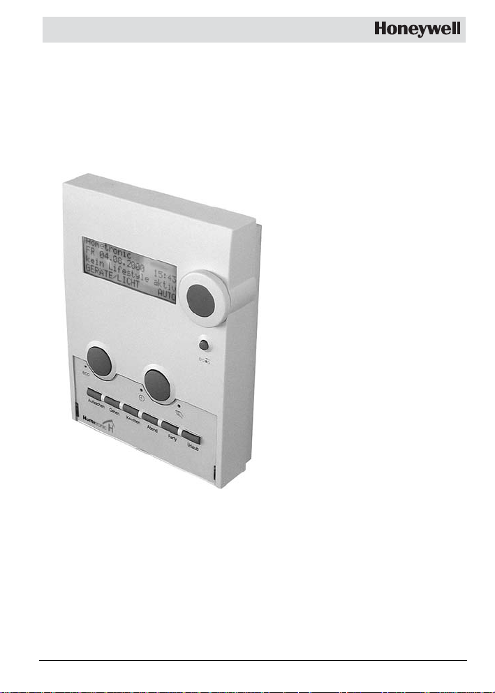
Hometronic
Manager
HCM 200
HCM 200D
Mounting and
Configuration
Page 2

Content
Content
Information on these instructions 2
Scope of supply 2
Power supply 3
Cable types 3
Voltage supply 4
Connection diagram 4
Boiler control 5
Boiler demand 5
Frost protection 5
Boiler regression 6
Mounting 7
Dismantling the Hometronic Manager 7
Selecting the mounting site 8
Wiring the plug-in connection 9
Flush mounting 9
Surface mounting 10
Fastening the operating unit 12
Activating the power supply 12
Inserting batteries 13
Assigning modules and rooms 14
Changing to the "Installation" submenu 14
Assigning a module or room 16
De-installing the module or room 20
Saving and getting system settings 21
Restoring the works settings 21
Appendix 23
Information for the fitter 23
Technical data 24
Help with problems 26
Glossary 28
1
Page 3
Overview
Information on these instructions
• Technical terms are identified by an * and are explained in
the glossary (from Page 28).
• Help for problems can be found from Page 26 on.
Symbols used
Warning
Caution!
Important information
Hint
For your information
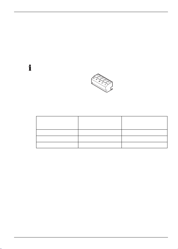
Scope of supply
The Hometronic Manager is supplied in four parts:
• 1 Mounting panel
• 1 Operating unit
• 1 Screw
• 1 Plug-in connection
3 Micro batteries each 1.5 V (type LR03) are additionally required.
Do not insert the batteries until the device is connected to the
voltage supply.
2
Page 4
Power supply
Cable types
POWER SUPPLY
Cable types
Only use the plug-in connection supplied.
All the cables to be connected must reach at least 15 cm out of
the wall.
The maximum length of the various cable types is specified in the
table below.
Cable type
JE-Y(St)Y 2×2×0.8
JE-LiYCY 2×2×0.8
NYM 1.5 mm2 120 m 150 m
Maximum length
voltage supply
40 m 100 m
40 m 100 m
Maximum length
boiler regression
3
Page 5
Power supply
Connection diagram
Voltage supply
• The Hometronic Manager can be supplied with voltage by
means of a plug-in power supply unit or a transformer.
• Use the Honeywell transformer HTU 10, HTS 10 or the plugin power supply unit HN 10.
• The device of an external supplier has to fulfill the following
requirements:
Input
voltage
230 V AC
1
Transformer voltage at 300 mA
Open-circuit
voltage
16 V AC or
17 V DC
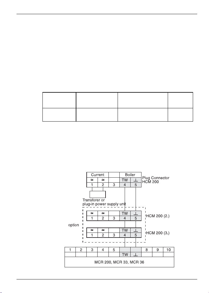
Connection diagram
The following connection diagram shows the wiring of a Hometronic Manager for the boiler regression* as well as the connection of a second or third Hometronic Manager (optional).
1
Output
voltage
12 V AC or DC 350 mA
Current
4
Page 6
Boiler control
Technical Data
BOILER CONTROL
Boiler demand
If the boiler control is carried out with external controllers, the
boiler demand* function can be activated with the HS 30 device
switch.
For information on how to assign the HS 30 device switch for the
boiler demand function please refer to Page 17.
For information on how to adapt the threshold value for the boiler
demand function, please refer to the operating instructions of the
Hometronic Manager in the chapter "Adapting basic system settings* (parameters*)".
Frost protection
The frost protection HK 10 consists of the device switch HS 30
and the room temperature sensor HCF 22.
A boiler demand function as described above has to be ensured
for the frost protection. Together with the room temperature sensor HCF 22 the Hometronic Manager triggers a boiler demand
function as soon as the value drops below the lower threshold for
frost protection.
For information on how to assign the room temperature sensor
HCF 22 as a frost protection sensor please refer to Page 18.
5
Page 7
Boiler control
Boiler regression
Boiler regression
The Hometronic Manager can be connected to a Honeywell
heating controller (MCR 35, MCR 36, MCR 40 or MCR 200) and
thus control the boiler directly.
► Prepare the cables in accordance with the table on Page 3.
► Lay the cable between the heating control and the Hometronic
Manager.
► Wire the plug-in connection of the Hometronic Manager to the
heating controller in accordance with the following figure.
If you connect several Hometronic Managers to a heating controller:
► Loop the connections through in accordance with the connec-
tion diagram on Page 4.
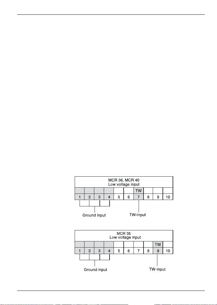
At the MCR 200 controller the temperature selection and ground
input lie at different terminals, depending on the respective design.
At the controllers MCR 35, MCR 36 and MCR 40 the temperature
selection and ground input lie at the following terminals:
6
Page 8
Mounting
g
Technical Data
MOUNTING
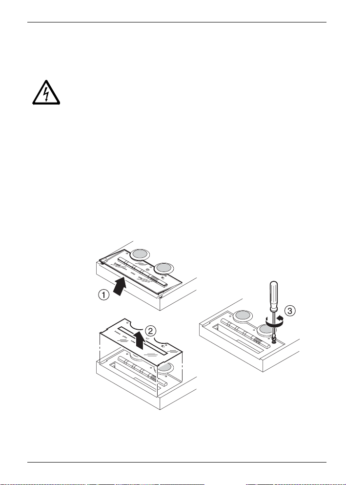
Danger to life through electric shock!
When transformers are cabled live contacts may lie free. Touch-
er!
Dan
Dismantling the Hometronic Manager
ing a live contact causes critical injuries.
► All work may only be carried out by authorized specialized
personnel.
► De-energize power supply.
► Lift the Plexiglas cover up at the edges with your fingers and
lift off the cover (1).
► Remove the inserted Lifestyle label (2).
► Unscrew the screw (3).
7
Page 9
Mounting
Selecting the mounting site
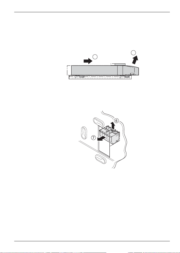
Separating the operating unit from the mounting panel
► Slide the unit upwards against the mounting panel (4).
► Lift the operating unit obliquely upwards (5).
4
5
Removing the plug-in connection
► Press the tongue of the retainer basket upwards (6).:
► Remove the plug-in connection from the retainer basket (7).
Selecting the mounting site
The Hometronic Manager communicates by radio with the
Hometronic components. When selecting the operation site ensure that there is sufficient distance to metallic objects such as
metal cabinets and doors, concrete ceilings with iron lattices and
radio devices such as radio headphones, etc. Select a central
site which is easily accessible.
8
Page 10

Mounting
Technical Data
The Hometronic Manager can be mounted:
• Via a flush-mounted box with the transformer HTU 10 (flush
mounting) or
• At a suitable point on the wall with the transformer HTS 10 for
switching cabinet mounting or with the plug-in power supply
unit HN 10 (surface mounting).
For dimensions of the Honeywell transformers, please refer to
the appendix from Page 23 on.
Wiring the plug-in connection
► Lay the cable from the plug-in power supply unit or trans-
former to the mounting site.
► Wire the plug-in connection.
Flush mounting
► Lay the cable directly from the
flush-mounted box to the retainer
basket of the mounting panel.
► Hold the plug-in connection as
shown in the adjacent figure (the
numbers 1 to 5 stand on their
head).
► Latch the plug-in connection into
the retainer basket.
9
Page 11

Mounting
Surface mounting
► Turn two screws half
into the flush-mounted
box (do not tighten
yet).
► Place the mounting
panel on the screws
and align it vertically.
► Tighten the screws.
For further information read "Fastening the operating unit".
Surface mounting
► Mark the drill-
ing holes.
► Drill the holes
and dowel
them.
10
Page 12

Mounting
Technical Data
► Break the recess out of
the mounting panel at one
of the two points marked
in the adjacent drawing.
► Lay the cable under the
retainer basket of the
mounting panel.
► Hold the plug-in connec-
tion as shown in the adjacent figure (the numbers
1 to 5 stand on their
head).
► Latch the plug-in connec-
tion into the retainer basket.
► Place the mounting panel
on the screws and align it
vertically.
► Tighten the screws.
11
Page 13

Mounting
Activating the power supply
Fastening the operating unit
► Place the operating unit slightly obliquely against the mounting
panel (1).
► Slide the operating unit upwards until the fastening hooks
touch the top.
► Press the operating unit flush against the mounting panel (2).
► Slide the operating unit down until its bottom projects over the
mounting panel (3).
► Insert and tighten the screw (4). If the screw does not find any
hold, slide the operating unit further downwards.
3
4
The operating unit is connected firmly to the mounting panel.
Activating the power supply
Depending on whether a plug-in power supply unit or a transformer is used:
► Plug in the plug-in power supply unit or
► Activate the fuse.
12
Page 14

Mounting
Technical Data
Inserting batteries
Only use the following micro batteries*:
• Alkali manganese LR03 (durability approx. 2 years) or
• 1.5 V rechargeable: LR03 (durability approx. 3/4 year)
► If necessary, use a small screwdriver to remove the old batter-
ies.
► Insert the batteries. Ensure
that the polarity is correct.
► When changing the battery:
Always replace all 3 batteries
simultaneously.
Inserting the Lifestyle label
► Insert the Lifestyle label (1).
► Place the plastic cover obliquely against the operating unit (2).
► Press the side latches of the plastic cover into the recesses in
the operating unit (3).
► Re-apply the Lifestyle foil and the plastic cover.
Mounting has been completed.
13
Page 15

Assigning modules and rooms
Changing to the "Installation" submenu
ASSIGNING MODULES AND ROOMS
First familiarize yourself with the operation of the Hometronic
Manager.
Changing to the "Installation" submenu
The rooms and modules* are assigned by means of the "Installation" submenu*.
The display shows the standard
display*, for example:
► Press the Dial button.
The cursor flashes in the lowest
line, the following text is displayed:
► Turn the Dial button to the right
until the cursor flashes in the
highest line.
► Press the Dial button.
The following text is displayed:
► Turn the Dial button to the left
until "Settings" is selected.
Hometronic
WE 29.10.1999 11:15
No lifestyle active
LIVING 20.0 C
MENU
SET DATE/TIME
ACTIVATE LIFESTYLE
LIVING 20.0 C
MENU
SET DATE/TIME
ACTIVATE LIFESTYLE
LIVING 20.0 C
LIFESTYLES
TIME PROGRAMS
DISPLAY
SETTINGS
LIFESTYLES
TIME PROGRAMS
DISPLAY
SETTINGS
14
Page 16

Assigning modules and rooms
Technical Data
► Press the Dial button.
The following text is displayed:
► Press the dial button again.
The following text is displayed:
► Turn the Dial button to the left
until further areas* are displayed for which an assignment
is possible:
Use the "Lifestyle" menu item to assign Lifestyles* to the HRD 20
remote control.
Use the "Tele interface" menu item to establish a remote connection to the Hometronic Manager, e.g. via phone or the Internet.
You require the software upgrade HCM200t to this purpose.
For further information please contact your Hometronic Partner.
Works settings of the menu items
Heating Shutters DEVICES/LIGHTS
LIVING HALL MODULE-1 MODULE-1
DINING STUDY MODULE-2 MODULE-2
KITCHEN HOBBY MODULE-3 MODULE-3
BEDROOM PARTY ... ...
BATH LIVING2 MODULE-32 MODULE-32
WC BEDROOM2
CHILD CHILD3
CHILD2 BATH2
INSTALLATION
DE-INSTALLATION
FUNCTION EXPANSION
SENSOR FUNCTION
HEATING
SHUTTERS
DEVICES/LIGHTS
SENSOR
SENSOR
BOILER DEMAND
LIFESTYLE
TELE INTERFACE
15
Page 17

Assigning modules and rooms
Assigning a module or room
Sensor Lifestyles Boiler demand
SENSOR-1 WAKE UP Switching module
SENSOR-2 ARRIVING Frost protec. sensor
SENSOR-3 LEAVING
... EVENING
SENSOR-16 PARTY
HOLIDAY
LIFESTYLE -7
...
LIFESTYLE -16
For information on changing the module or room name please
refer to the operating instructions of the Hometronic Manager in
the section "Changing names".
Assigning a module or room
Example: Assigning a shutter module.
► Activate the teach-in at the shutter module as described in the
mounting instructions of the module.
► Change to the "Installation" submenu at the Hometronic Man-
ager as described on Page 14.
The following text is displayed:
► Turn the Dial button until "Shut-
ters" is selected.
► Press the Dial button.
The following text is displayed,
for example:
HEATING
SHUTTERS
DEVICES/LIGHTS
SENSOR
HEATING
SHUTTERS
DEVICES/LIGHTS
SENSOR
MODULE-2 *
MODULE-3
MODULE-4
MODULE-5
16
Page 18

Assigning modules and rooms
Technical Data
An * is displayed next to the modules already assigned.
► Turn the Dial button until the
desired module is selected, e.g.
MODULE-2 *
MODULE-3
MODULE-4
► Press the Dial button.
An * is displayed next to the selected module.
MODULE-5
MODULE-2 *
MODULE-3 *
MODULE-4
MODULE-5
The module is assigned.
Assigning an HS 30 device switch for the boiler demand
► Wire the device switch to the boiler demand as described from
Page 3 on.
► Activate the teach-in at the device switch as described in the
mounting instructions of the module.
► Change to the "Installation" submenu at the Hometronic Man-
ager as described on Page 14.
The following text is displayed:
► Turn the Dial button until "Boiler
demand" is selected.
► Press the Dial button.
The following text is displayed:
HEATING
SHUTTERS
DEVICES/LIGHTS
SENSOR
SHUTTERS
DEVICES/LIGHTS
SENSOR
BOILER DEMAND
SWITCHING MODULE
FROST PROTEC.
SENSOR
17
Page 19

Assigning modules and rooms
Assigning a module or room
► Press the Dial button again
An asterisk is displayed next to
"Switching module".
SWITCHING MODULE
*
FROST PROTEC.
SENSOR
The HS 30 device switch is assigned to the Hometronic Manager for the
boiler demand.
Assigning the room temperature sensor HCF 22 for the
frost protection
► Wire the room temperature sensor to the boiler demand as
described from Page 3 on.
► Change to the "Installation" submenu at the Hometronic Man-
ager as described on Page 14.
The following text is displayed:
► Turn the Dial button until "Boiler
demand" is selected.
► Press the Dial button.
The following text is displayed:
► Turn the Dial button until "Frost
protec. sensor" is selected.
► Press the Dial button again.
The cursor flashes next to the "Frost protec. sensor".
SHUTTERS
DEVICES/LIGHTS
SENSOR
BOILER DEMAND
SHUTTERS
DEVICES/LIGHTS
SENSOR
BOILER DEMAND
SWITCHING MODULE
FROST PROTEC.
SENSOR
SWITCHING MODULE
FROST PROTEC.
SENSOR
18
Page 20

Assigning modules and rooms
Technical Data
The Hometronic Manager is ready for data transfer.
► Activate the teach-in at the room temperature sensor as de-
scribed in the mounting instructions of the room temperature
sensor.
An * is displayed next to "Frost protec. sensor" after a successful teach-in.
The room temperature sensor HCF 22 is assigned for frost protection.
For information on how to adapt the threshold value for frost
protection, please refer to the operating instructions of the
Hometronic Manager in the chapter "Adapt system basic settings
(parameters)".
19
Page 21

Assigning modules and rooms
De-installing the module or room
De-installing the module or room
The "De-installation" submenu has the same menu structure as
the "Installation" submenu.
Example: De-installing a shutter module.
► Follow the steps described on
Page 14.
The following text is displayed:
► Turn the Dial button until "De-
Installation" is selected.
► Press the Dial button.
The following text is displayed:
► Turn the Dial button until "Shut-
ters" is selected.
► Press the Dial button.
The following text is displayed,
for example:
Only those modules are displayed which have been assigned
beforehand (* next to the module designation).
► Turn the Dial button until the
module to be de-installed is selected, for example:
INSTALLATION
DE-INSTALLATION
FUNCTION EXPANSION
SENSOR FUNCTION
INSTALLATION
DE-INSTALLATION
FUNCTION EXPANSION
SENSOR FUNCTION
HEATING
SHUTTERS
DEVICES/LIGHTS
SENSOR
HEATING
SHUTTERS
DEVICES/LIGHTS
SENSOR
MODULE-2 *
MODULE-3 *
MODULE-2 *
MODULE-3 *
20
Page 22

Assigning modules and rooms
Technical Data
► Press the Dial button.
The module is removed from
the list.
The shutter module is de-installed.
MODULE-2 *
Saving and getting system settings
Why save settings?
Always save your settings after you have carried out changes.
This ensures that settings are not lost, even when power fails or
when batteries are flat.
For information on how to save and get the system settings
please refer to the operating instructions of Hometronic Manager
in the "Adapting" chapter.
Restoring the works settings
If you restore the works settings*, all the current adjustments and
assignments such as module names, time programs and Lifestyles* are lost.
In order to use the current configuration later again you have to
save the settings beforehand.
► Change to the "Settings" submenu as described in the operat-
ing instructions of the Hometronic Manager.
► Select "Configuration".
► " Select "Factory setup".
The following text is displayed:
► Press the Dial button.
Factory Setup
Actual configuration will
be deleted!
NO YES
21
Page 23

Assigning modules and rooms
Restoring the works settings
The appendix of the operating instructions contains a table with
the works settings of the modules, time programs and Lifestyles.
The works settings are restored.
22
Page 24

Appendix
Technical Data
APPENDIX
Information for the fitter
After mounting carry out the following checks:
• Hometronic Manager wired correctly?
• Date and time set correctly?
• Version Number noted (refer to operating instructions)?
• All components assigned correctly?
• Do modules, rooms and Lifestyles have speaking names?
After mounting and configuration have been completed it is advisable to familiarize the customer with the basic functions of the
Hometronic Manager.
• Please refer to the "Description" chapter of the operating
instructions of the Hometronic Manager for further information.
• Explain the various operating modes of the Hometronic Manager.
• Explain to the customer the advantages of automatic operating modes, such as:
• Presence simulation
• Shading and wind function
• Partial automatic mode
• Explain the possibilities offered by manual operation directly
at the device, e.g. at the heating controller.
• If appropriate, point out the possibilities offered by extending
the respective installation of the Hometronic System.
23
Page 25

Appendix
Technical data
Technical data
Type designation HCM 200
Electrical connection 12 V AC/DC, max. 350 mA
Wattage 4 VA
Degree of protection IP 30
Protection class 2
Radio interference sup-
pression
Device dimensions 127 x 170 x 40 mm (W x H x D)
Operating temperature 0 °C ... 40 °C
Device dimensions HCM 200
CE-conform, R&TTE
24
Page 26

Appendix
Technical Data
Device dimensions transformer HTU
Device dimensions transformer HTS 10
25
Page 27

Appendix
Help with problems
Help with problems
Error messages in display
Error message Cause / Remedy
► Check at which Hometronic module the batteries
are weak.
Please check the
clock
Factory reset
Cold start
Device No. lost
CAUTION!
Automatic function
not possible in Manual
mode!
► Insert new batteries (see section on Page 13).
► Set the date and time as described in the operat-
ing instructions of the Hometronic Manager.
The Hometronic Manager is started with the works
settings if the data in the Hometronic Manager were
faulty or were lost and no settings were saved.
► Install the modules and rooms again or call our
service.
The Hometronic Manager carries out a cold start if
the data in the Hometronic Manager were faulty or
were lost, but settings had been saved beforehand.
The saved settings are used. Any changes which
were carried out after the last saving process are
lost.
► Carry out the last changes again.
► Remove the batteries and insert them again.
► If the message is still displayed, call the Service
Department.
The Hometronic Manager is disabled.
► Enable the disabling function as described in the
operating instructions of the Hometronic Manager.
Automatic functions can only be activated in Automatic mode.
► Activate the Automatic mode.
26
Page 28

Appendix
Technical Data
Error message Cause / Remedy
LIVING
No entries exist. In-
sert?
In this example the "LIVING" module does not have
any entries.
► Confirm correspondingly.
NO YES
!
Faulty signal of an external sensor.
► Check where the signal comes from as de-
scribed in the operating instructions of the sensor.
► Check the batteries.
► Improve the transfer conditions as described in
the operating instructions of the sensor.
WIND
or
CAUTION!
Wind function is
The wind protection is active. The setpoint cannot
be changed at the respective modules. The function
is de-activated automatically when the wind force
has not exceeded the threshold for 20 minutes.
active!
Faults
Fault Cause / Remedy
The temperature in a
room is controlled
incorrectly
No display at the
display
Functioning of the
Hometronic Manager
is not possible or
only to a limited
extent
The radio connection in the Hometronic system
may be faulty.
► Check the fault display at the storey controller
and at the HR 50.
The power supply is interrupted.
► Check the power supply.
► Call the Service Department or bring the device
to the After-Sales. Inform the After-Sales of the
software version number which you noted in the
operating instructions.
27
Page 29

Appendix
Glossary
Glossary
Areas
Those menu items in the "Installation" submenu at which an assignment is possible: Heating (H),
lamps/devices (L) shutters (S),
sensors, Lifestyles, boiler demand
and telecom.
Basic system settings
Refer to the parameters.
Boiler demand
Hometronic controls the heating
boiler via a setpoint.
Boiler regression
Controlling of the heating boiler
with an analog control device of
Honeywell.
Lifestyle
Autonomous control of the Hometronic Manager by a combination of
setpoints.
Micro battery
Battery with the designation
LR 03.
Module
Components of the Hometronic
system, device of Honeywell.
Parameters
Basic system settings which can
be used when no other values are
entered (name, setpoints, offsets
etc.).
Standard display
Basic display in the display of the
Hometronic Manager. Is displayed
after the Back button has been
pressed (possibly several times).
Submenu
All the menus with the exception
of the standard display and the
main menu.
Works settings
Certain modules, Lifestyles and
time programs are set by Honeywell ex works (refer to the table in
the operating instructions).
28
Page 30

Great Britain Germany
Honeywell Honeywell GmbH
Honeywell House 71101 Schönaich
Arlington Business Park Böblinger Straße 17
Bracknell Telephone (+49) (0) 7031 637-01
Berkshire RG12 1EB www.hometronic.de
The right is reserved to make
modifications
Honeywell Inc. hereby declares that this device complies with the basic requirements and
other relevant regulations of guideline 1999/5/EC. The declaration of conformity of the
product can be requested from the manufacturer.
Note to non-EU countries: This product may only be used if operation in the 433 MHz and
868 MHz frequency band is permissible.
This company is certificated to
EN1H-0277GE51 R0904A
 Loading...