

Page 1
Hometronic
Voice & Web
Interface
HCI 300
Installation and Operation
Page 2

Page 3

Contents
Contents
System requirements 3
HCM 200 software version 3
Telephone 3
Overview 4
For your information 4
Application 4
Scope of delivery 4
Scope of functions 5
Dialing into the Hometronic System (poll Lifestyle) 5
Alarm output at a telephone 5
Internet access to the Hometronic System 6
Installation 7
Checking wiring of telephone jack 9
Installing Hometronic Voice & Web Interface 10
Description 13
Button on Hometronic Voice & Web Interface 13
LEDs on Hometronic Voice & Web Interface 14
Startup 15
1
Page 4

Contents
Performing binding 17
Activating binding at Hometronic Voice & Web Interface 17
Activating binding at Hometronic Manager 18
Successful binding 19
Failed binding 20
Operation 21
First call 21
Changing Lifestyle 22
Changing language 23
Accepting alarm/message text 23
Suppressing alarm/message text 24
Changing settings at Hometronic Manager 26
Switching to "Internet parameters" menu of Hometronic
Manager 26
Changing number of rings 29
Changing PIN 29
Changing to "Alarm Parameters" submenu 30
Changing alarm telephone numbers 32
Linking Lifestyle to alarm/message text 33
Appendix 35
Glossary 35
Help with problems 37
Technical data 39
Dimensions 39
2
Page 5

System requirements
System requirements
HCM 200 software version
To make use of the functions of the Hometronic Voice & Web
Interface HCI 300, the HCM 200 requires software version 5.00 or
higher.
If you are currently using a lower version in the HCM 200, please
contact your installer regarding an update.
Telephone
Devices with DTMF dialing* only
3
Page 6

Overview
Overview
For your information
Technical terms are explained in the Appendix on Page 35 of these
instructions. They are identified in the text by an *.
Application
The Hometronic Voice & Web Interface HCI 300 enables you to
remotely poll and regulate the Lifestyles* of your Hometronic Manager
via a telephone line. This can be done with a telephone or via the
Internet. In addition, the HCI 300 outputs telephone messages
automatically. For this purpose, the Hometronic Voice & Web Interface
is connected before the existing communication equipment
(telephone, fax machine, etc.).
Scope of delivery
• Hometronic Voice & Web Interface HCI 300
• Power supply with cable
• Telephone cable with TAE plug* (HTK 200, German connection
variant)
• Telephone cable with RJ11 plug* (HTA 200, international
connection variant for connection to an adapter)
4
Page 7

Scope of functions
Scope of functions
The Hometronic Voice & Web Interface HCI 300 is a modem with
three basic functions:
1. Dialing into the Hometronic System (poll Lifestyle)
2. Alarm output at any desired telephone
3. Internet access to the Hometronic System
Dialing into the Hometronic System (poll Lifestyle)
Dialing into the Hometronic System is established via the standard
telephone line (TAE connection). When dialing in, the HCI 300
responds with "Please enter your PIN". It then provides spoken
information as to which Lifestyle is activated or asks which Lifestyle
you would like to activate. The HCI 300 guides you through the
individual steps via spoken commands. You must confirm each entry
with the pound sign (#).
Alarm output at a telephone
An alarm could be triggered when a smoke detector activates a
Lifestyle and a Lifestyle is assigned to the message text, for example.
The message text is forwarded to the entered telephone numbers.
You can assign a Lifestyle from 1 to 16 to each of the five alarm
messages. An assigned alarm message is deactivated by the Lifestyle
number 0. The HCI 300 says the message text to the receiver,
regardless of whether it’s a person, answering machine or a mailbox.
The voice message of the message texts can be suppressed.
5
Page 8

Scope of functions
If the first telephone number is busy, an alarm message can be output
to a second telephone number. The first and second telephone
numbers are called three times in an alternating fashion until the call
is confirmed with the pound key (#). An alarm message is not
repeated.
When using the HX 10 expansion module and activated priority
input "1", you must suppress the alarm so that the alarm message is
not repeated (see "Suppressing alarm/message text" on Page 24).
Internet access to the Hometronic System
A Hometronic service provider is required for Internet access. This
provider enables you to communicate with the Hometronic System via
the Internet. To establish the connection to the server, enter a "0"
instead of the telephone number when entering the "alarm telephone
numbers". In addition to the dialing-in and the alarm output (described
above), access to the Hometronic via the Internet offers additional
functions from the provider.
6
Page 9
Installation
A standard telephone cable connected to an N-encoded*
telephone jack is required for the HCI 300 (see "Checking
wiring of telephone jack" on Page 9).
The HCI 300 communicates with the Hometronic
Manager via a wireless connection.
Caution!
► Install other electronic devices in a distance of at least
30 cm from the HCI 300.
► Do not wind the power cable around the HCI 300.
► When selecting the operating site, ensure that there is
sufficient distance to metallic objects such as steel
reinforcements, metallic wallpapers, etc.
► The distance between the HCI 300 and the HCM 200
and other wireless components may not exceed 30 m.
Installation
7
Page 10
Installation
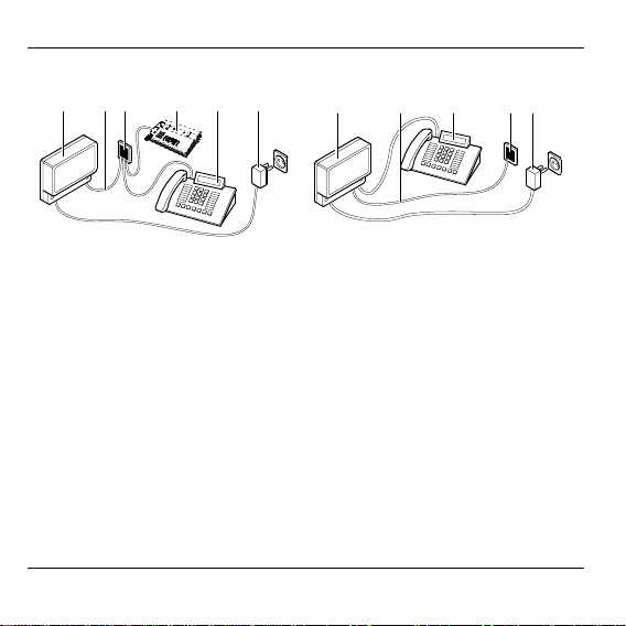
German connection variant International connection variant
3 64 51
2
3 4 51
2
1 Hometronic Voice & Web Interface
HCI 300
2 Telephone cable (HTK 200) 2 Telephone cable (HTA 200)
3 Telephone jack 3 Local telephone
4 Fax machine (optional) 4 Telephone jack
5 Local telephone 5 Power supply
6 Power supply
8
1 Hometronic Voice & Web Interface
HCI 300
Page 11
Installation
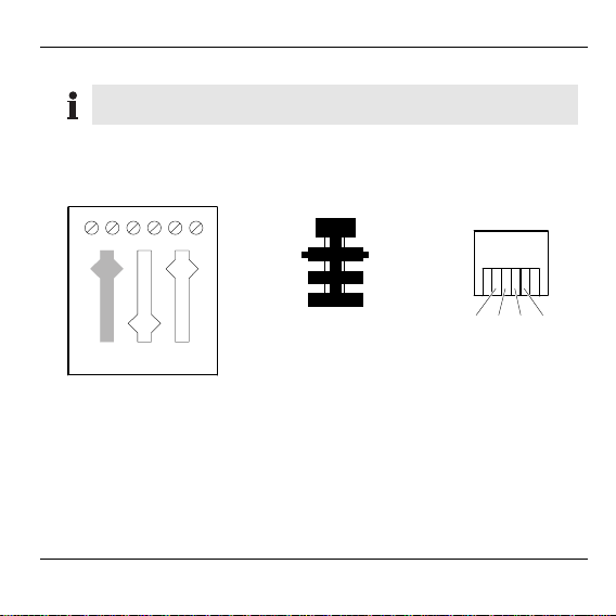
Checking wiring of telephone jack
The telephone jack used for the HCI 300 connection must be
N-encoded.
► Check the wiring of the telephone jack against the following figure.
Telephone jack
23 5416
Lb W b2ELa a2
NFN
TAE plug (HTK 200)
RJ11 plug
(HTA 200)
4
5
6
1 yellow (La) 0 none
2red (Lb) 1black
3 none 2 red
4 none 3 green
5 black (b2) 4 yellow
6 green (a2) 5 none
3
2
1
1234
9
Page 12
Installation
Installing Hometronic Voice & Web Interface
Preparation
The HCI 300 must be connected to the leftmost N-encoded
connection of the telephone jack.
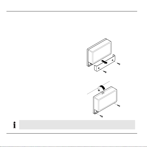
► Remove the front cover of the
HCI 300.
The jacks and terminals can
now be seen.
Securing Hometronic Voice & Web Interface
► Mark the holes for mounting the
HCI 300.
► Secure the HCI 300 with three
screws.
Do not reattach the front cover of the HCI 300 until startup is
complete.
10
Page 13
Installation
y
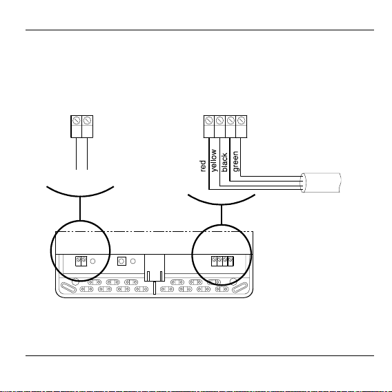
Connecting Hometronic Voice & Web Interface
► Connect the telephone cable to the HCI 300 as shown in the figure.
Note the polarity of the voltage supply when doing so.
Voltage supply Line In Phone
123412
GND
+9 V DC
Power suppl
HTA 200 or
HTK 200
Voltage
supply
Line In Phone
123412
11
Page 14
Installation
► Insert the TAE plug of the HCI 300 into the leftmost N-encoded
connection of the telephone jack.
You can also connect the local telephone to the HCI 300
directly. Take the "Terminal assignment at Hometronic Voice
& Web Interface" into consideration when doing so.
Terminal assignment at Hometronic Voice & Web Interface
Terminal 1
1GND
2+9 V DC
Terminal 2
1redLine In
2yellow
3blackPhone
4green
12
HTK 200 cable to TAE telephone jack
Connection to telephone or answering
machine
Page 15

Description
Description
1 Green LED
(telephone connection)
2 Binding button
1 2 3
3 Red LED
(binding, wireless connection)
Button on Hometronic Voice & Web Interface
Button press Meaning
Briefly (< 2 sec.)
5 x within 10 sec.
Test wireless communication.
(The red LED flashes briefly.)
Activate binding.
(The red LED flashes regularly.)
13
Page 16

Description
LEDs on Hometronic Voice & Web Interface
Red LED
Display Meaning
LED on No wireless connection to Hometronic Manager
LED flashes
briefly
LED flashes Binding active
LED off Standby
Green LED
Display Meaning
LED on Telephone busy
LED flashes
regularly
LED flashes
irregularly
Display when connected to voltage supply
Data being transferred to Hometronic Manager
Telephone line free (normal operation)
Data being transferred to Internet server
If the HCI 300 is connected to the voltage supply (e.g. at first
startup or after a power failure), both LEDs go on and off
repeatedly.
14
Page 17

Startup
Startup
The HCI 300 can only be used via a telephone with DTMF
dialing*.
► To start up the HCI 300, you must remove the front cover (see
"Installing Hometronic Voice & Web Interface" on Page 10).
► Connect the HCI 300 to the voltage supply by plugging the power
supply into an electrical outlet.
Both LEDs on the HCI 300 go on and off repeatedly. Both LEDs go
out after a short time.
If one of the LEDs does not go out, the cabling is not correct
(see "Connecting Hometronic Voice & Web Interface" on
Page 11).
► Pick up the receiver of the telephone attached to the connection jack
of the HCI 300.
A dial tone can be heard.
If a dial tone cannot be heard, the cabling is not correct (see
"Help with problems" on Page 37).
► Perform binding.
15
Page 18

Startup
If other communication devices (fax machine, additional telephone,
etc.) are used in addition to the telephone:
► Check to make sure that the other devices function properly.
16
Page 19

Performing binding
Performing binding
The HCI 300 must be assigned to the Hometronic Manager before
they can exchange data. This process is called "binding".
Two steps must be carried out to perform binding:
• Activating binding at Hometronic Voice & Web Interface
• Activating binding at Hometronic Manager
To perform binding, the front cover must be removed (see
"Installing Hometronic Voice & Web Interface" on Page 10).
Activating binding at Hometronic Voice & Web Interface
► Press the Binding button at least 5 times within 10 seconds.
The red LED in the HCI 300 flashes. The HCI 300 is now in
Binding mode.
Binding mode remains active for a maximum of 3 minutes.
After this period, the HCI 300 returns to normal operation. The
previous settings remain unchanged.
17
Page 20

Performing binding
Activating binding at Hometronic Manager
The Hometronic Manager is in automatic mode.
The display of the Hometronic
Manager shows, for example:
► Press the Input button.
The cursor flashes on the bottom
line.
► Turn the Input button to the right until
"Menu" is selected.
► Press the Input button.
The following text is displayed:
► Turn the Input button to the left until
"Settings" is selected.
► Press the Input button.
The following text is displayed:
18
Hometronic
WE 29.10.1999 11:15
No Lifestyle active
LIVING 20.0 C
MENU
SET DATE/TIME
ACTIVATE LIFESTYLE
LIVING 20.0 C
LIFESTYLES
TIME PROGRAMS
DISPLAY
SETTINGS
LIFESTYLES
TIME PROGRAMS
DISPLAY
SETTINGS
INSTALLATION
DE-INSTALLATION
FUNCTION EXTENSION
SENSOR FUNCTION
Page 21

► Press the Input button.
The cursor is in the "Installation"
submenu.
► Turn the Input button to the left until
"Tele Interface" is selected.
► Press the Input button.
The cursor is in the "Installation Tele
Interface" submenu.
Performing binding
HEATING
SHUTTERS
DEVICES/LIGHT
SENSOR
SENSOR
BOILER REQUEST
LIFESTYLE
TELE INTERFACE
INSTALLATION
TELE INTERFACE
► Press the Input button.
An * appears after "Tele Interface".
INSTALLATION
TELE INTERFACE *
Successful binding
Binding has been successful if the flashing red LED in the HCI 300
goes out and then only flashes sporadically.
► Reattach the front cover of the HCI 300.
19
Page 22

Performing binding
Failed binding
Binding has failed if the red LED in the HCI 300 is still flashing
regularly. Wireless data transfer has not been established or was
interfered with.
► Carry out the following steps after a failed binding:
– Repeating binding
– Improving transmission and repeating binding
Repeating binding
► Reactivate Binding mode on the HCI 300 and on the Hometronic
Manager as described above.
Binding is repeated.
Improving data transfer
► Remove/avoid interfering, shielding devices, e.g.:
– wireless headphones
– wireless telephone base stations
(may not be located within 70 cm of the HCI 300)
► Move the HCI 300 and the Hometronic Manager closer together (max.
distance: 30 m).
20
Page 23

Operation
Operation
The HCI 300 is operated via the keypad of the telephone used to call
the device. Follow the announcements of the HCI 300.
First call
► Call the HCI 300 from an external telephone.
The HCI 300 responds with the words: "Please enter your PIN".
If other communication equipment is connected (fax machine,
answering machine, etc.), the "Please enter your PIN" request
is not announced after the call is accepted.
► Enter the PIN* "1111" via the keypad of your telephone (see also
"Changing PIN" on Page 29).
► Press the pound sign (#) on the telephone to confirm the PIN.
If the PIN is entered incorrectly several times, the HCI 300
ends the call.
► Follow the subsequent announcements of the HCI 300.
Ending a call
Each call to the HCI 300 is to be ended as described in the
announcement.
21
Page 24

Operation
Changing Lifestyle
Lifestyles on the Hometronic Manager are specified by name.
For the individual Lifestyles, the HCI 300 uses the numbers 1
to 16. For assignment to remain clear, you should create a
numbered list of the Lifestyles.
► Call the HCI 300 via an external telephone.
The HCI 300 responds with the words: "Please enter your PIN".
If other communication equipment is connected (fax machine,
answering machine, etc.), the "Please enter your PIN" request
is not announced after the call is accepted.
► Enter your PIN* via the keypad of your telephone (see also "Changing
PIN" on Page 29).
► Press the pound sign (#) on the telephone to confirm.
► Follow the subsequent announcements of the HCI 300.
22
Page 25

Operation
Changing language
When changing the language from German to English or vice
versa, a special PIN must be entered at the HCI 300.
Proceed as follows after installation and startup:
► Call the device via an external telephone.
The HCI 300 responds with the words "Please enter your PIN".
► Enter the PIN 1422055.
► Press the pound sign (#) on the telephone to confirm.
The device replies with "Goodbye". If this process is repeated, you
will hear the message "Auf Wiederhören".
Accepting alarm/message text
To receive an alarm/message text, an alarm phone number
must be specified, a lifestyle must be linked to an
alarm/message text and an alarm must be active at the
HCI 300 (see "Changing alarm telephone numbers" on
Page 32 and "Linking Lifestyle to alarm/message text" on
Page 33).
If the HCI 300 contacts you with an alarm/message text, proceed as
follows:
► Press the pound sign (#) on the telephone to confirm.
The alarm/message text is not repeated.
23
Page 26

Operation
Special case: When using the HX 10 expansion module and active
priority input "1", the alarm/message text is also repeated after
pressing the pound sign (#). The alarm/message text must be
suppressed here (see "Suppressing alarm/message text" on
Page 24).
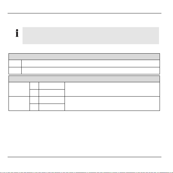
Suppressing alarm/message text
When using the HX 10 expansion module and active priority input "1",
the alarm/message text is also triggered again after pressing the
pound sign (#). The alarm/message text must be suppressed here:
► Call the HCI 300 from an external telephone.
The HCI 300 responds with the words: "Please enter your PIN."
► Enter the PIN* "1422010".
► Enter the number of the reported alarm.
Alarm text Number
Fire Alarm
Burglar Alarm
Water Alarm
Alarm
Trouble Report
► Enter "00".
► Press the pound sign (#) on the telephone to confirm the PIN.
24
1
2
3
4
5
Page 27

Operation
The following shows all the input for a water alarm: "1422010300".
The alarm is suppressed.
Once the cause of the alarm has been eliminated, the alarm
must be reactivated at the HCM 200 (see "Linking Lifestyle to
alarm/message text" on Page 33).
25
Page 28

Changing settings at Hometronic Manager
Changing settings at Hometronic Manager
Switching to "Internet parameters" menu of Hometronic
Manager
In the "Internet parameters" submenu, you can individually
adapt the settings for the selection of the HCI 300 from a
telephone (number of rings before the HCI 300 responds and
PIN). The values for the other parameters in this submenu are
required for the Internet connection and established by the
respective ISP*. For additional information, please contact
Honeywell directly (see back cover of these instructions).
Parameters Meaning
No. of rings
Telephone PIN
GHS* Port Adr.
GHS* IP Adr.
ISP* Telephone No.
ISP* Username
ISP* Password
26
Number of rings before the HCI 300
responds
Telephone PIN
Port address of the Global Home Server
(GHS)
TCP/IP network address of GHS*
Telephone number of the Internet service
provider (ISP)
User name for ISP*
Password for ISP*
Page 29

Changing settings at Hometronic Manager
The display of the Hometronic
Manager shows, for example:
► Press the Input button.
The cursor flashes on the bottom
line.
► Turn the Input button to the right until
"Menu" is selected.
► Press the Input button.
The following text is displayed:
► Turn the Input button to the left until
"Settings" is selected.
► Press the Input button.
The following text is displayed:
Hometronic
WE 29.10.1999 11:15
No Lifestyle active
LIVING 20.0 C
MENU
SET DATE/TIME
ACTIVATE LIFESTYLE
LIVING 20.0 C
LIFESTYLES
TIME PROGRAMS
DISPLAY
SETTINGS
LIFESTYLES
TIME PROGRAMS
DISPLAY
SETTINGS
INSTALLATION
DE-INSTALLATION
FUNCTION EXTENSION
SENSOR FUNCTION
27
Page 30

Changing settings at Hometronic Manager
► Turn the Input button to the left until
"Internet parameters" is selected.
SENSOR FUNCTION
SUMMER TIME
PARAMETERS
INTERNET PARAMETERS
► Press the Input button.
The following text is displayed:
HIM Parameter Menu
Please wait! 127
No. of rings 4
Telephone PIN 1111
► Wait until the display "Please wait!
127" changes to "Current values:".
HIM Parameter Menu
Current values:
No. of rings 4
Telephone PIN 1111
If "Default settings" or "No Parameters" appears in the display,
interference has affected the wireless communication between
the Hometronic Manager and the HCI 300 (see "Help with
problems" on Page 37).
28
Page 31

Changing settings at Hometronic Manager
Changing number of rings
► Turn the Input button to the left until
"No. of rings" is selected.
► Press the Input button and change the number of rings by turning the
Input button.
► Press the Input button.
HIM Parameter Menu
Current values:
No. of rings 4
Telephone PIN 1111
The number of rings for the HCI 300 must be higher than that
of the connected devices (fax machine, answering machine,
etc.).
Changing PIN
The PIN "1111" set at the factory can be changed in order to
prevent misuse.
► Turn the Input button to the left until
"Telephone PIN" is selected.
► Press the Input button and change the first two digits of the PIN by
turning the Input button.
► Press the Input button and change the last two digits of the PIN by
turning the Input button.
HIM Parameter Menu
Current values:
No. of rings 4
Telephone PIN 1111
29
Page 32

Changing settings at Hometronic Manager
► Press the Input button.
By selecting and confirming "Set basic system settings", all
Internet parameters are reset to the predefined values. The
current parameters are transferred to the HCI 300 via "Send
all parameters".
Changing to "Alarm Parameters" submenu
The settings for calls of the HCI 300 to an external telephone are
changed in the "Alarm Parameter Menu".
The display of the Hometronic
Manager shows, for example:
► Press the Input button.
The cursor flashes on the bottom
line.
► Turn the Input button to the right until
"Menu" is selected.
► Press the Input button.
The following text is displayed:
30
Hometronic
TH 09.10.2003 11:15
No Lifestyle active
LIVING 20.0 C
MENU
SET DATE/TIME
ACTIVATE LIFESTYLE
LIVING 20.0 C
LIFESTYLES
TIME PROGRAMS
DISPLAY
SETTINGS
Page 33

Changing settings at Hometronic Manager
► Turn the Input button to the left until
"Settings" is selected.
LIFESTYLES
TIME PROGRAMS
DISPLAY
SETTINGS
► Press the Input button.
The following text is displayed:
INSTALLATION
DE-INSTALLATION
FUNCTION EXTENSION
SENSOR FUNCTION
► Turn the Input button to the left until
"Alarm Parameters" is selected.
SENSOR FUNCTION
SUMMER TIME
PARAMETERS
ALARM PARAMETERS
► Press the Input button.
The following text is displayed:
Alarm Parameter Menu
Please wait! 015
Alarm Phone No. 1 >
Alarm Phone No. 2 >
► Please wait until the display "Please
wait! 015" changes to "Current
values:".
Alarm Parameter Menu
Current values:
Alarm Phone No. 1 >
Alarm Phone No. 2 >
If "Default settings" or "No Parameters" appears in the display,
interference has affected the wireless communication between
the Hometronic Manager and the HCI 300 (see "Help with
problems" on Page 37).
31
Page 34

Changing settings at Hometronic Manager
Changing alarm telephone numbers
Here you enter the two telephone numbers called by the HCI 300 in
an alarm situation. The HCI 300 calls the first and second telephone
numbers three times in an alternating fashion until the call is
confirmed with the pound key (#).
► In the "Alarm Parameter Menu" turn
the Input button to the left while
"Alarm Phone No. 1" is selected.
► Press the Input button.
The following text is displayed:
Alarm Parameter Menu
Current values:
Alarm Phone No. 1 >
Alarm Phone No. 2 >
Alarm Phone No. 1
0¦¦¦¦¦¦¦¦¦¦¦¦¦¦¦¦¦¦¦¦¦
¦¦¦¦¦
OK
► Press the Input button and change the selected number by turning the
Input button.
► Press the Input button.
The changed number is saved. The cursor flashes at the next
position.
The voice message begins 5 seconds after the call is
accepted. By putting a "P" (pause) after the telephone
number, you can delay the start of the voice message. Each
"P" entered delays the voice message by the duration
between two rings.
32
Page 35

Changing settings at Hometronic Manager
The Hometronic Manager only takes characters to the left of
the first arrow "<-" into account.
► Turn the Input button to the right until the cursor flashes on OK.
► Press the Input button.
Linking Lifestyle to alarm/message text
Here you enter the text output by the HCI 300 when activating a
Lifestyle.
► In the "Alarm Parameter Menu" turn
the Input button to the left while the
desired text is selected.
Current values:
Alarm Phone No. 1 >
Alarm Phone No. 2 >
Fire Alarm >
You can choose between the following message texts: "Fire
Alarm", "Burglar Alarm", "Water Alarm", "Alarm", "Trouble
Report".
► Press the Input button.
The following text is displayed:
Fire Alarm
Lifestyle No. 0
Voice Message yes
OK
This message text is deactivated when "Lifestyle No. 0" is set.
► Press the Input button and change the selected number by turning the
Input button.
33
Page 36

Changing settings at Hometronic Manager
► Press the Input button.
The following text is displayed:
Fire Alarm
Lifestyle No. 2
Voice Message yes
OK
► Press the Input button in order to change the voice message, if
necessary.
If Voice Message is set to "yes", the set message text is
output. If "no" is set, the HCI 300 responds, but does not
output any specific message text.
► Turn the Input button to the right until the cursor flashes on OK.
► Press the Input button.
34
Page 37

Appendix
Glossary
Binding
Assignment of the HCI 300 to
the Hometronic Manager.
DTMF dialing
Abbreviation for Dual-Tone
Multi-Frequency dialing). Two
tones are transmitted for each
digit.
F-coding
(remote speaker encoding)
Due to projections on the TAE
plug, the plugs of telephones
only fit in the F-encoded jacks.
GHS
Global Home Server
ISP
Internet Service Provider
Appendix
Lifestyle
User-defined actions which
guide various devices and
modules through a specified
sequence.
N-encoding
(message terminal encoding)
Due to projections on the TAE
plug, the plugs of corresponding devices only fit in the Nencoded jacks.
PIN
(personal identification number)
The term is used for an
ID number or a personal code.
RJ11 plug
Standardized connection type
for telecommunication devices.
35
Page 38

Appendix
TAE plug
(telephone connection unit)
Type of connection used to
connect telecommunication
devices to the telephone network.
36
Page 39

Help with problems
Problem Cause/Solution
LEDs do not go out
after startup.
Red LED still
flashes regularly
after binding.
Local telephone
does not receive
dial tone.
Other device (fax
machine,
telephone) does not
function properly.
Cabling faulty.
► Check cabling of HCI 300 (see
"Checking wiring of telephone jack" on
Page 9).
Communication with Hometronic Manager
HCM 200 may have been interfered with.
► Repeat binding (see "Performing binding"
on Page 17).
► Improve the transmission (see
"Improving data transfer" on Page 20).
Cabling faulty.
► Check cabling of HCI 300 (see
"Checking wiring of telephone jack" on
Page 9).
Cabling faulty.
► Check cabling of HCI 300 (see "Terminal
assignment at Hometronic Voice & Web
Interface" on Page 12).
Appendix
37
Page 40

Appendix
Display of
Hometronic
Manager switches
to "Default settings"
or "No Parameters"
instead of "Current
values:".
38
Communication with Hometronic Manager
HCM 200 may have been interfered with.
► Check power supply to HCI 300.
– or –
► Repeat binding (see "Performing binding"
on Page 17).
► Improve the transmission (see
"Improving data transfer" on Page 20).
Page 41

Technical data
Mains voltage 9 V DC
Current consumption (max.) 150 mA
Ambient temperature (max.) 45 °C
Protection class IP 30
Connection to the PSTN (public switched telephone network) tested in
January 1998 in accordance with TBR 21.
Dimensions
140 163
185
207
All dimensions in mm
Appendix
39
Page 42

Appendix
Notes
40
Page 43

Page 44

Honeywell GmbH
Böblinger Straße 17
D – 71101 Schönaich
Germany
Phone: (01801) 466-390
This company is certificated to
Wireless approval in:
AT, BE, CH, DE, DK, ES, FI, FR, GB, IE, IT, LU, NL, NO
The right is reserved to make modifications. This document is definitive for the
enclosed product and replaces all previous publications.
No. 7157682 EN1H-0255 GE51R0104
 Loading...