

Page 1
H808C
Convertible Dehumidifier Controller
Application
The H808C Dehumidifier Controller provides automatic
low voltage control of dehumidifiers in central heating
systems. The humidity controller has an spst, snap-acting,
dust-proof switch and is designed for wall or surface duct
mounting.
MODELS:
■ H808C1029: Premier White™.
■ H808C1037: Beige.
ELECTRICAL RATING: 50 VA at 24 Vac.
MAXIMUM AMBIENT TEMPERATURE: 125° F [52° C].
SWITCH DIFFERENTIAL: 5 percent RH, nonadjustable.
SET POINT ADJUSTMENT RANGE: 20 to 80 percent
RH; positive ON and OFF positions.
Installation
CAUTION
1. Installer must be a trained, experienced service
technician.
2. Disconnect power supply before beginning
installation.
3. Conduct a thorough checkout before leaving
installation.
WALL MOUNTING
1. Locate the humidity controller about 5 ft [1.5m]
above the floor on an inside wall.
NOTES:
a. Be sure the humidity controller is subject to average
room temperature and average relative humidity.
The maximum temperature at the location selected
must not exceed 125° F [52° C].
b. The humidity controller can be mounted directly on
the wall.
2. Drill a small hole in the wall.
3. Run low voltage wiring to the location and pull about
6 in. [152 mm] of wire through the hole.
NOTE: Plug the opening to prevent drafts from affecting
humidity controller operation.
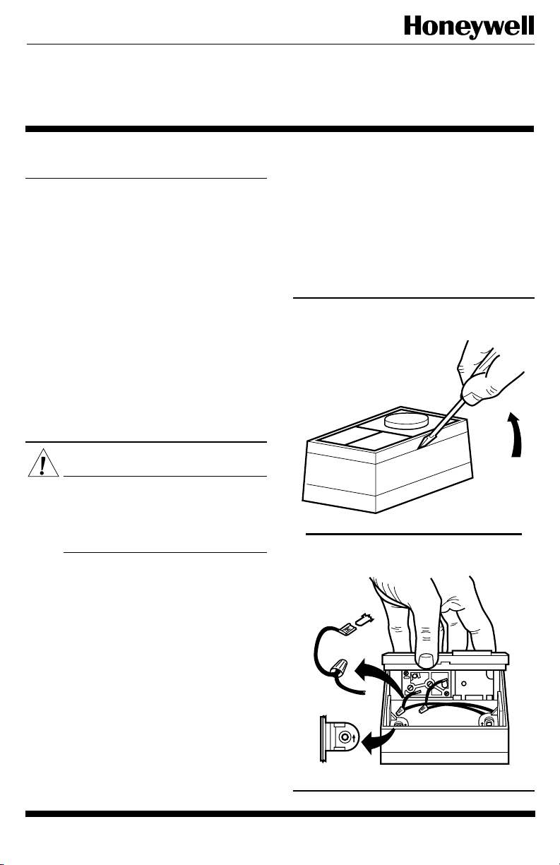
4. Remove the humidity controller assembly by prying
with a screwdriver in the notch on the bottom of the case
(Fig. 1).
5. Position the case horizontally over the wires with the
arrows on the tabs pointing up and secure the case to the
wall using the two screws provided.
6. Connect the wires to the humidity controller assembly using leadwires and wire nuts provided (see Wiring
section and Fig. 2).
7. Tuck the wires into the bottom of the case.
8. Snap the cover assembly into the case (Fig. 2).
Fig. 1—Removing humidity controller assembly
from case.
M9262
Fig. 2—Wiring connections on humidity
controller.
QUICK-CONNECT
WIRE LEAD
UP
MOUNTING
HOLE (2)
COVER
CASE
UP
UP
M9263
WIRE
NUT
HUMIDIFIER
LEADWIRE
1 69-0821
J.F. • 3-94 • ©Honeywell Inc. 1994 • Form Number 69-0821
Page 2
DUCT MOUNTING
1. Locate the humidity controller at least 8 in. [203 mm]
upstream of the humidifier in the return air duct.
NOTE: If mounting near an elbow area, keep the humidity
controller 6 in. [152 mm] upstream of the elbow so the
element will be affected by the normal airflow (Fig. 3)
.
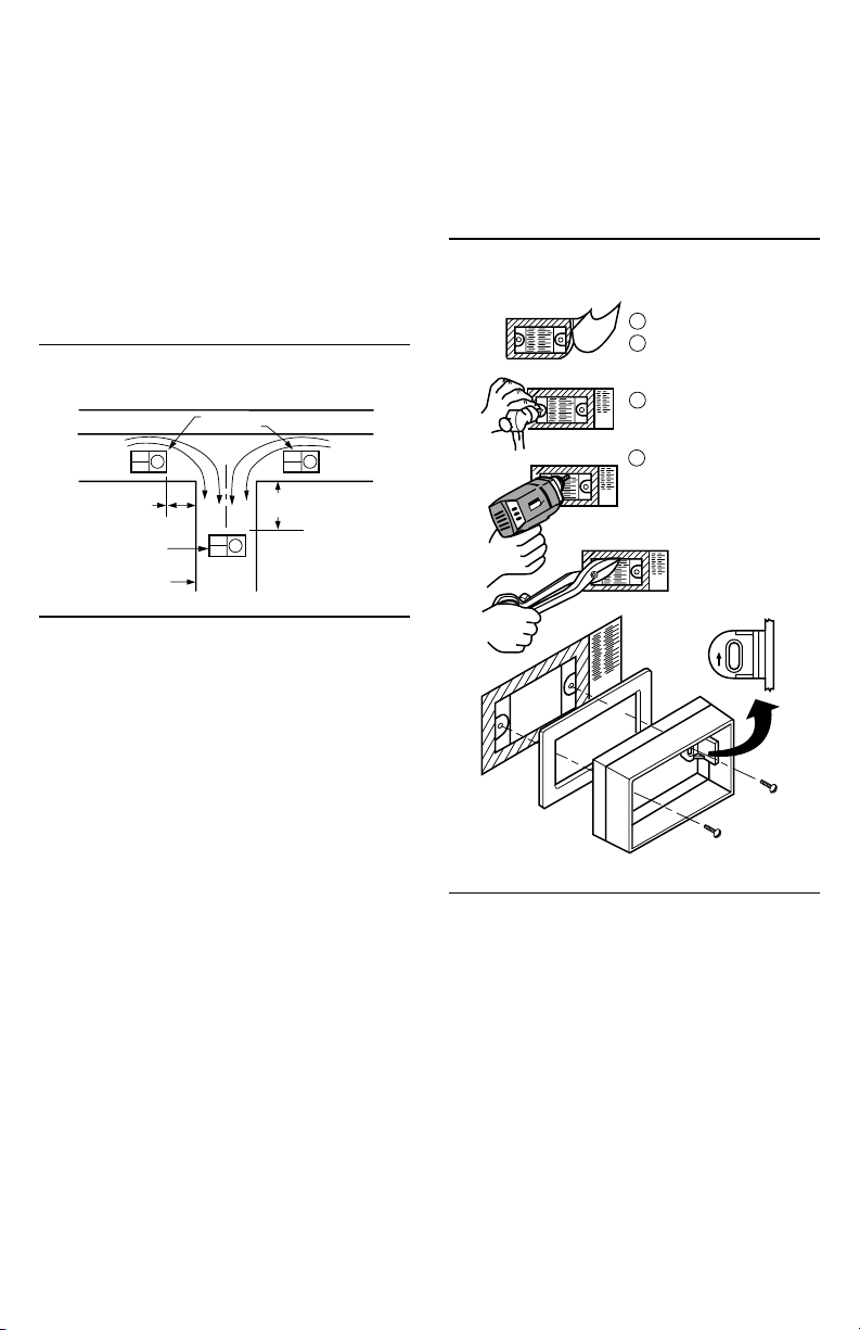
2. Using Fig. 4 and the instructions on the template,
drill two mounting holes (3/32 in. [2.4 mm]) and 12 sensing
holes (1/4 in. [6.4 mm] in diameter) in the duct. (The
sensing holes allow return air to reach the nylon sensing
element and operate the humidity controller.)
NOTE: If desired, cut a square hole in the duct as indicated
on the template in place of the sensing holes.
Fig. 3—Selecting a duct location for the humidity controller.
ALTERNATE
RETURN
AIR
6 in. [152 mm]
MINIMUM
BEST LOCATION
RETURN AIR DUCT
LOCATIONS
15 in. [381 mm]
MINIMUM
RETURN
AIR
M9277
7. While holding wire in place, mount the case on the
duct using the two mounting screws provided.
NOTE: Tighten the screws firmly so the gasket seals the
space between the case and the duct (Fig. 4).
8. Connect the wires to the humidity controller assembly using leadwires and wire nuts supplied (see Wiring
section and Fig. 2).
9. Snap cover assembly into the case.
Fig. 4—Mounting humidity controller on return
air duct.
LOCATE TEMPLATE.
1
2
PEEL BACKING
FROM TEMPLATE
AND APPLY TO DUCT.
3
PUNCH AND DRILL
TWO 3/32 IN. [3 mm]
MOUNTING HOLES.
DRILL MINIMUM
4
OF TWELVE
1/4 IN. [7 mm] HOLES.
OR
DRILL OR PUNCH
CORNER HOLES AND
CUT OUT SQUARE
ON SOLID LINE.
3. Remove the protective backing from the foam gasket
included with each control and apply the foam gasket to the
template in the location indicated.
4. Remove the cover and humidity controller assembly
from the case by prying with a screwdriver in the notch in
the bottom of the case (Fig. 1).
5. Run low voltage wire from the humidity controller to
the template (Figs. 5 and 6).
6. Lay wire over one side of the foam gasket allowing
about 6 in. [152 mm] for connection to the humidity controller. Wire can enter the humidity controller case from
any direction.
NOTE: Do not position wire directly under the two stand-
off projections at the back of the case. If wire is under
these projections, the case will not seat tightly against
the gasket, causing air leakage and possible improper
operation.
CASE
TEMPLATE
GASKET
UP
M9264
69-0821 2
Page 3

Fig. 5—Typical parallel wiring diagram of H808C with T87F/Q539A combination for dehumidification
and mildew control.
H808C
T87F/Q539A INTERNALSCHEMATIC
FILTER
LIGHT
HEAT OFF FANAUTO ONCOOL
3 2
BX O
PROVIDE OVERLOAD PROTECTION AND DISCONNECT MEANS
1
AS REQUIRED.
HEATING DAMPER MOTOR, IF USED.
2
3
CLOGGED FILTER SWITCH OR COOLING PANEL CONNECTION.
Fig. 6—Typical series wiring diagram of H808C with T87F/Q539A combination for dehumidification and
mildew control.
H808C
FILTER
LIGHT
R1
T87F/Q539A INTERNALSCHEMATIC
R1
T87F
TEMPERATURE
FALL
W1 Y1
HEAT OFF COOL
W Y
HEATING
RELAY OR
VALVE COIL
COOLING
CONTACTOR
COIL
T87F
TEMPERATURE
FALL
W1 Y1
FIXED
COOL
ANTICIPATOR
G RHR
FAN RELAY
COIL
FIXED
COOL
ANTICIPATOR
ADJUSTABLE
HEAT
ANTICIPATOR
ADJUSTABLE
HEAT
ANTICIPATOR
1
M18627
HEAT OFF FANAUTO ONCOOL
3 2
BX O
PROVIDE OVERLOAD PROTECTION AND DISCONNECT MEANS
1
AS REQUIRED.
HEATING DAMPER MOTOR, IF USED.
2
3
CLOGGED FILTER SWITCH OR COOLING PANEL CONNECTION.
HEAT OFF COOL
W Y
HEATING
RELAY OR
VALVE COIL
COOLING
CONTACTOR
COIL
G RHR
FAN RELAY
COIL
1
M18626
3 69-0821
Page 4

Fig. 7—Typical wiring diagram for H46C,E.
1
L1
(HOT)
L2
POWER SUPPLY. PROVIDE DISCONNECT MEANS
1
AND OVERLOAD PROTECTION AS REQUIRED.
HUMIDITY
RISE
H46C, E CONTROLLER
DEHUMIDIFIER
EXHAUST FAN
OR AIR
CONDITIONER
M9297
WIRING
All wiring must comply with local codes and ordinances. Make wiring connections according to to dehumidifier instructions if available; otherwise, see typical
wiring diagrams in Figs. 5 and 6.
Settings
HUMIDITY CONTROLLER ADJUSTMENT
The humidity comfort range of a living space is generally between 25 and 50 percent RH. However, as the
outdoor temperature changes, the humidity level on the
humidity controller may need to be reset to assure maximum comfort.
To reduce the relative humidity, reduce the set point approximately three percent RH every 24 hours. To increase
the relative humidity, increase the set point approximately
three percent RH every 24 hours.
WALL MOUNT HUMIDITY CONTROLLER
Set the humidity set point according to the prevailing
outdoor temperature to provide optimum relative humidity
control for most installations. Adjust the humidity level to
a particular structure using the procedure above.
DUCT MOUNT HUMIDITY CONTROLLER
If the temperature at the humidity controller location
on the return air duct is less than 80° F [27° C] ,use the
procedure for wall mounted humidity controllers.
If the air surrounding the humidity controller is greater
than 80° F [27° C], reset the recommended settings to
compensate for the higher ambient temperature. High ambient temperatures will cause the humidity controller to control
at an increased setting. To determine the compensated set
point for surface mounted humidity controllers with high
ambient temperatures, use the following procedure:
1. With a bulb type thermometer, accurately determine
the surrounding duct temperature at the humidity controller
location.
2. Decrease the recommended setting about five percent
for each 5° F [3° C] above 80° F [27° C] at the humidity
controller.
For example, if the humidity controller is set at 25 per-
cent and the temperature at the humidity controller is 90° F
[32° C], the compensated set point should be 15 percent.
(This is the 25 percent setting less 10 percent for the 10° F
[6° C] above ambient temperature.)
Checkout
Place the system in operation and observe through at
least one complete cycle to make certain that all components are functioning properly.
Home and Building Control Home and Building Control Helping You Control Your World
Honeywell Inc. Honeywell Limited—Honeywell Limitée
1985 Douglas Drive North 740 Ellesmere Road
Golden Valley, MN 55422 Scarborough, Ontario
69-0821 4
Printed in U.S.A.
M1P 2V9
QUALITY IS KEY
 Loading...