

Page 1
Installation Instructions for the
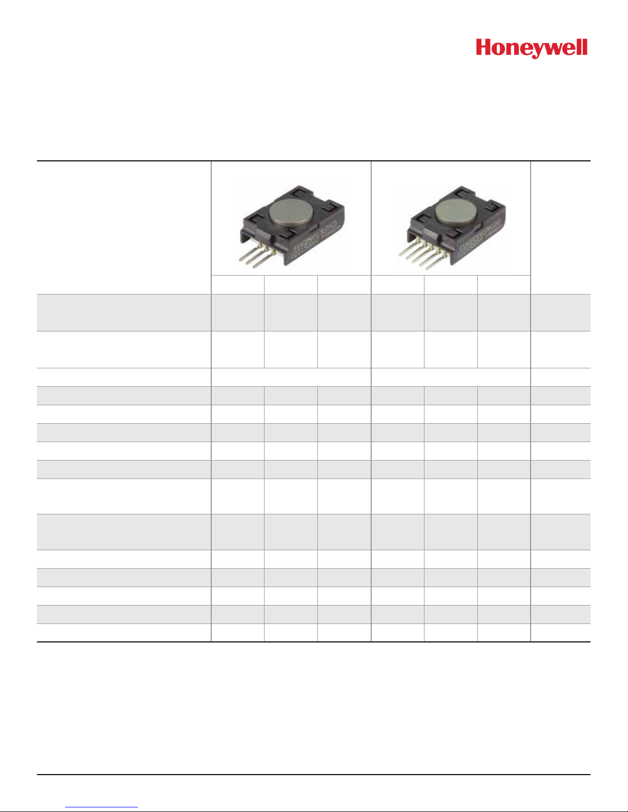
Honeywell Force Sensors
FSA Series Compensated/Amplified
32311097
Issue B
Table 1. Operating Specifications
Analog Digital
Characteristic
Min. Typ. Max. Min. Typ. Max.
Supply voltage (V
3.3 Vdc
5.0 Vdc
supply
):
1, 2, 3
3.0
4.75
3.3
5.0
3.6
5.25
3.0
4.75
3.3
5.0
3.6
5.25
Supply current:
3.3 Vdc
5.0 Vdc
Power input
Operating temperature range
Compensated temperature range
4
5
Storage temperature range
Startup time (power up to data ready)
Response time
—
—
2.0
2.6
—
—
—
—
2.8
3.9
3.9
4.6
13 20
0 [32] — 70 [158] 0 [32] — 70 [158]
5 [41] — 50 [122] 5 [41] — 50 [122]
40 [40] — 85 [185] 40 [40] — 85 [185]
— — 5 — — 3
— 1 — — 0.42 0.84
Clipping limit:
upper
lower
—
2.5
—
—
97.5
—
—
—
—
—
—
—
SPI/I2C voltage level:
low
high
—
—
—
—
—
—
—
80
—
—
20
—
Pull up on SDA/MISO, SCL/SCLK, SS — — — 1 — — kOhm
Accuracy
Total Error Band
6
8
— — ±3 — — ±3 %FSS
— — ±5 — — ±5 %FSS
Unit
Vdc
mA
mW
°C [°F]
°C [°F]
°C [°F]
ms
ms
%V
supply
%V
supply
7
BFSL
Output resolution — — — 12 — — bits
Long term stability9
1
Sensors are either 3.3 Vdc or 5.0 Vdc based on the catalog listing selected.
2
Ratiometricity of the sensor (the ability of the device output to scale to the supply voltage) is achieved within the specified operating voltage.
3
The sensor is not reverse polarity protected. Incorrect application of supply voltage or ground to the wrong pin may cause electrical failure.
4
Operating temperature range: The temperature range over which the sensor will produce an output proportional to force.
5
Compensated temperature range: The temperature range over which the sensor will produce an output proportional to force within the specified
performance limits.
6
Accuracy: The maximum deviation in output from a Best Fit Straight Line (BFSL) fitted to the output measured over the force range at 25°C [77°F].
Includes all errors due to force non-linearity, force hysteresis, and non-repeatability.
7
Full Scale Span (FSS): The algebraic difference between the output voltage at full scale force and the output at zero force.
8
Total Error Band (TEB): Combined error from calibration, accuracy and temperature effects over the compensated temperature range at 5.0 V from
15 %FSS to 95 %FSS.
9
Long-term stability after 1000 hr of operation at 25°C [77°F].
Sensing and Internet of Things
— ±1.3 —
— ±1.3 — %FSS
Page 2

Honeywell Force Sensors
Issue B
FSA Series Compensated/Amplified
Table 2. Environmental Specifications
Characteristic Parameter
Humidity 0% to 95% RH, non-condensing
Vibration MILSTD202, Method 214, Condition 1E (16.9 G)
Shock MILSTD202, Method 213, Condition F (1500 G)
1
Life
1
Life may vary depending on specific application in which the sensor is utilized.
Table 3. Materials
Component Material
Covers high temperature polyamide
Plunger stainless steel 316
Substrate alumina, ceramic
Adhesives epoxy, silicone
Electronic components ceramic silicon, glass, solder
1
Contact Honeywell customer service for detailed material information.
1
1 million full scale force cycles minimum
32311097
Table 4. Absolute Maximum Specifications
Characteristic Min. Max. Unit
Supply voltage 0.3 6.0 Vdc
Voltage on any pin 0.3 V
Digital interface clock frequency:
SPI
2
I
C
ESD susceptibility (human body model) 2 — kV
Storage temperature range 40 [40] 85 [185] °C [°F]
Overforce limit — 6804 [15] g [lb]
Minimum operating voltage 2.8 Vdc
Lead soldering time and temperature 4 s max. at 220°C [428°F]
50
100
+ 0.3 V
supply
800
400
kHz
2 Sensing and Internet of Things
Page 3

Honeywell Force Sensors
0
10
20
30
40
50
60
70
80
90
100
1
2 3456
7
8
9
10
5% Total Error Band
0
F
min.
F
max.
Compensated Force Range
Force (example unit)
Output (%Vsupply)
0.8 x Vsupply
Output (V) =
x (Force
applied
) + 0.10 x Vsupply
Ideal
Force
range
80%
Output (% of 2
14
counts) =
x (Force
applied
) + 10%
Force
0
10
20
30
40
50
60
70
80
90
100
1
2 3456
7
8
9
10
5% Total Error Band
0
F
min.
F
max.
Compensated Force Range
Force (example unit)
Output (%Vsupply)
Ideal
Issue B
FSA Series Compensated/Amplified
Figure 2. Transfer Function Limits
Analog Version
Digital Version
1
32311097
1
Transfer Function “A” is shown. See Figure 1 for other available transfer function options.
Sensing and Internet of Things 3
Page 4

Honeywell Force Sensors
25,02
[0.24]
25,02
Issue B
FSA Series Compensated/Amplified
Figure 2. Mounting Dimensions (For reference only: mm/in.)
Analog version
[0.99]
23,57
[0.93]
ø12,70
[0.5]
6,11
5,74
[0.23]
2X 3,94
[0.15]
3X 2,54
[0.1]
Pin 1
3X 1,31
[0.05]
3X 0,63
[0.02]
3X 6,48
[0.26]
3X 0,61
[0.02]
12,19
[0.48]
Plunger
1,79
[0.07]
7,1
[0.28]
17,36
[0.68]
32311097
5,7
[0.22]
8,25
[0.32]
3,68
[0.14]
Digital version
Function Pin 1 Pin 2 Pin 3
analog V
4X 2,54
[0.1]
5X 1,31
[0.05]
5X 0,63
[0.02]
Pin 1
3,57
[0.14]
5,74
[0.23]
2X 3,94
5X 6,48
[0.26]
5X 0,61
[0.02]
supply
Vout GND
[0.99]
23,57
[0.93]
ø12,70
[0.5]
12,19
[0.48]
Plunger
1,79
[0.07]
17,36
[0.68]
7,1
[0.28]
8,25
[0.32]
5,7
[0.22]
3,68
[0.14]
4 Sensing and Internet of Things
Function Pin 1 Pin 2 Pin 3 Pin 4 Pin 5
SPI GND V
2
C GND V
I
supply
supply
SS MISO SCLK
N/C SDA SCL
Page 5

Force Sensors
Issue B
FSA Series Compensated/Amplified
WARNING
PERSONAL INJURY
DO NOT USE these products as safety or emergency stop
devices or in any other application where failure of the
product could result in personal injury.
Failure to comply with these instructions could result in
death or serious injury.
Warranty/Remedy
Honeywell warrants goods of its manufacture as being free
of defective materials and faulty workmanship during the
applicable warranty period. Honeywell’s standard product
warranty applies unless agreed to otherwise by Honeywell
in writing; please refer to your order acknowledgment or
consult your local sales office for specific warranty details.
If warranted goods are returned to Honeywell during the
period of coverage, Honeywell will repair or replace, at its
option, without charge those items that Honeywell, in its sole
discretion, finds defective. The foregoing is buyer’s sole
remedy and is in lieu of all other warranties, expressed or
implied, including those of merchantability and fitness for a
particular purpose. In no event shall Honeywell be liable for
consequential, special, or indirect damages.
32311097
Find out more
Honeywell serves its customers through
a worldwide network of sales offices and
distributors. For application assistance, current
specifications, pricing or name of the nearest
Authorized Distributor, contact your local sales
office.
To learn more about Honeywell’s sensing and
switching products, call
+1-815-235-6847 or 1-800-537-6945, visit
sensing.honeywell.com, or e-mail inquiries to
info.sc@honeywell.com
Honeywell Sensing and Internet of Things
9680 Old Bailes Road
Fort Mill, SC 29707
honeywell.com
While Honeywell may provide application assistance personally,
through our literature and the Honeywell web site, it is buyer’s
sole responsibility to determine the suitability of the product in
the application.
Specifications may change without notice. The information we
supply is believed to be accurate and reliable as of this writing.
However, Honeywell assumes no responsibility for its use.
32 3 110 9 7BEN | B | 1/17
© 2017 Honeywell International Inc. All rights reserved.
 Loading...