

Page 1
FSX™ Fire and Flame Detectors
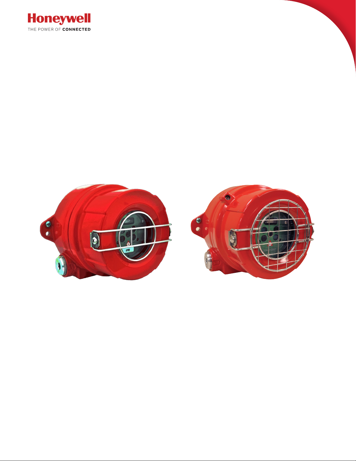
Model FS20X™ Series
FS20X UV/VIS/Dual IR
Standard Model EN54 Model
User Manual
Multi-Spectrum Infrared/Ultraviolet Electro-Optical
Multi-Spectral Digital WideBand IR Sensor with Ultraviolet
Phototube
Radiant Energy Fire and Flame Detector
Page 2

Read and understand this manual before
installing or operating equipment.
No part of this document may be copied or reproduced without the express written permission
of Honeywell Analytics.
This manual is subject to change without notice.
© 2015-2018 by Honeywell International Inc.
While this information is presented in good faith and believed to be accurate, Honeywell disclaims the implied
warranties of merchantability and fitness for a particular purpose and makes no express warranties except as
may be stated in its written agreement with and for its customers.
In no event is Honeywell liable to anyone for any indirect, special or consequential damages. The information and
specifications in this document are subject to change without notice.
ACCTTL, ALERT-1, ALARM-2, ALERT-1: ALARM 2, ALERT-1: ALARM-2, ATAG, Clean Room Sentry, COP-i,
Complete Optical Path Integrity, CM1, CM1-A, DartLogic, FireLogic, Fire Signature Analysis, FireBusI, FireBusII,
FirePic, FirePicII, FirePicIII, FirePix, FirePicture, FSC, Fire Sentry Corporation, Fire Sentry Corp., FSX, All FSX
Nomenclature Variations (such as: FS2, FS2X, FS3, FS3X, FS4, FS4X, FS5, FS5X, FS6, FS6X, FS7, FS7X,
FS8, FS8X, FS9, FS9X, FS10X, FS10X, FS11, FS11X, FS12, FS12X, FS14, FS14X, FS15, FS15X, FS16,
FS16X, FS17, FS17X FS18, FS18X, FS19, FS19X, FS20, FS20X, FS24, FS24X, FS24XN, FS26, FS26X,
FS26XN), FS7-2173-2RP, FS System 7, FS System 10, FS7-2173, FS7-2173-RP, FS2000, FS System 2000,
High Speed Flame & Surveillance Detector, Multi-Spectrum QuadBand Triple IR, Multi-Spectrum TriBand, MultiSpectrum Tri-Band, Near Band Infrared, Near Band IR, NearBand IR, QuadBand IR, Room Sentry, RS, RS2,
SM2, SM3, SS, SS2, SS2X, SS2-A, SS3, SS3-A, SS3X, SS4, SS4-A, SS4X, SnapShot, SLR-BIT, SuperBus,
SuperSentry, System 2000, Tri-Mode Plot, QuadBand Triple IR Plus, TriBand, Tri-Band, “FS & FSC triangle
logo’s”, WBIR, Wide Band Infrared, WideBand IR, Wide Band IR
are registered trademarks of Honeywell International Inc.
Other brand or product names are trademarks of their respective owners.
Honeywell Analytics
Page 3

FS20X Fire and Flame Detectors
Table of Contents
Introduction ����������������������������������������������������������������������������������������������������������������5
Restricted Materials Chart for China RoHS ����������������������������������������������������������� 5
WEER Directive Disposal Chart �����������������������������������������������������������������������������6
Safety Information ��������������������������������������������������������������������������������������������������6
Contacting Honeywell Analytics ����������������������������������������������������������������������������7
Principle of Operation �������������������������������������������������������������������������������������������� 9
Features and Benefits �������������������������������������������������������������������������������������������10
Typical Applications �������������������������������������������������������������������������������������������� 11
Glossary ����������������������������������������������������������������������������������������������������������������12
Product Variations ���������������������������������������������������������������������������������������������������� 13
FS20X-211-22-2 ���������������������������������������������������������������������������������������������������� 13
Field of View Restrictor ����������������������������������������������������������������������������������������15
Installation ����������������������������������������������������������������������������������������������������������������16
Installation Practices ��������������������������������������������������������������������������������������������16
Mounting Instructions ������������������������������������������������������������������������������������������18
Opening the Detector �������������������������������������������������������������������������������������������20
Field Connectors ���������������������������������������������������������������������������������������������������22
User-selectable Configuration Switches �������������������������������������������������������������23
Detector Connections �������������������������������������������������������������������������������������������24
Wiring and Terminal Connections �����������������������������������������������������������������������25
Start-up and commissioning �������������������������������������������������������������������������������� 28
Drawings ������������������������������������������������������������������������������������������������������������������� 30
Dimensions ������������������������������������������������������������������������������������������������������������30
Operation ������������������������������������������������������������������������������������������������������������������ 31
Configuring the Detector �������������������������������������������������������������������������������������� 31
LED Status Indicators ������������������������������������������������������������������������������������������� 34
Normal Operation ��������������������������������������������������������������������������������������������������34
Alarm Condition ����������������������������������������������������������������������������������������������������35
Fault Conditions ���������������������������������������������������������������������������������������������������� 36
Maintenance ������������������������������������������������������������������������������������������������������������� 37
Specifications ����������������������������������������������������������������������������������������������������������� 38
Mechanical ������������������������������������������������������������������������������������������������������������ 38
Electrical ����������������������������������������������������������������������������������������������������������������38
Environmental �������������������������������������������������������������������������������������������������������39
Performance ����������������������������������������������������������������������������������������������������������39
Hazardous Area Classifications ���������������������������������������������������������������������������39
Performance Certifications ����������������������������������������������������������������������������������39
Additional Performance Specifications ���������������������������������������������������������������40
Hazardous Location Detector Markings �������������������������������������������������������������� 42
Warranty �������������������������������������������������������������������������������������������������������������������� 43
Index �������������������������������������������������������������������������������������������������������������������������45
3
Page 4

FS20X Fire and Flame Detectors
4
Page 5

FS20X Fire and Flame Detectors
部件名称
有害物质
铅
(Pb)汞(Hg)镉(Cd)
六价铬
(Cr(VI))
多溴联苯
(PBB)
多溴二苯醚
(PBDE)
感光探测器
X0000
0
本表格中未列出的所有部件和配件包含的有害物质都没有超过 GB/T26572 所要求的限制。
本表格依据SJ/T11364 的规定编制
O:表示该有害物质在该部件所有均质材料中的含量均在 GB/T26752 规定的限量要求以下。
×:表示该有害物质至少在该部件的某一均质材料中的含量超出 GB/T26 572 规定的限量要求。
2004Y2007C_1A05005ChinaRoHSDeclaration07(PbDet)3Ju ly2017
Introduction
Read and understand this manual before installing or operating the detector. No
part of this document may be copied or reproduced without the express written
permission of Honeywell Analytics. While this information is presented in good
faith and believed to be accurate, Honeywell disclaims the implied warranties
of merchantability and fitness for a particular purpose and makes no express
warranties except as stated in its written agreement. In no event is Honeywell liable
to anyone for any indirect, special, or consequential damages. The information and
specifications in this document are subject to change without notice.
Restricted Materials Chart for China RoHS
5
Page 6
FS20X Fire and Flame Detectors
WARNING
!
CAUTION
!
N OT I C E
WEER Directive Disposal Chart
EN
EU Directive 2012 /19/EU: Waste Electrical and Electronic
Equipment (WEEE)
This sy mbol indicates that t he product must not be disposed
of as general industrial or dome stic w aste . This produc t
should be disposed of through suit able W EEE disposal
facilities. For more information about disposal of this
product, contact your local au thority, distributor or the
manufacturer.
FR
DIREC TIVE 2012 /19/UE: Relative aux déchets
d’Equipements Électriques et Électroniques (DEEE)
Ce symbole indique que le produi t ne doit pas être éliminé en
tant que déchet industriel ou ménager. Ce produit doit être
envoyé vers des site s de valorisation ou él imination des D3E.
Pour plus d’informations sur la mise au rebut de ce produit,
contactez les autorités compétentes, votre distributeur ou le
fabricant.
IT
DIRETTIVA 2012/19/UE: Rifiuti di Apparecchiature
Elettriche ed Elettroniche (RAEE)
Questo simbol o indica che il prodotto non deve essere
trat tato come rifiuto industriale o domestico. Questo
prodotto deve essere smaltito in idonei impianti di
smaltimento specifici per R AEE. Per ulteriori informazioni
sullo smaltimento di questo prodot to contattare l ’ente lo cale
preposto, il distributore o il produttore
ES
DIREC TIVA 2012/19/UE: Residuos de Aparatos Eléctricos
y Electrónicos (R AEE)
Este símbolo indica que el producto no puede ser desechado
como re siduo doméstico o industrial genérico. E ste
producto debe ser desechado en inst alaciones de reciclado
RAEE adecuadas . Para más información acerca del desecho
de este produc to, contac te con su autoridad loc al, el
distribuidor o el fabricante.
NL
RICHTLIJN 2012/19/EU: Betreffende Afgedankte
Elektrische en Elektronische Apparatuur (AEEA)
Dit symbool geef t aan dat het product niet als algemeen
industrieel of huishoudelijk afval mag worden weggego oid.
Het product dient te worden afgevoerd via ge schik te
afvalverwijderingsinst allaties voor AE EA.
Neem vo or meer informatie over de af voer van dit product
contact op met uw lokale overheid , distributeur of de
fabricant.
DE
RICHTLINIE 2012/19/EU: über Elektro- und Elek tronikAltgeräte
Diese s Symbol zeigt an, dass dieses Produk t nicht
als Hausmüll oder kommunaler Müll entsorgt werden
darf. E s sollte zum Recycl ing zu einer geeignete W EEE
Entsorgungsanlagen gegeben werden . Um weitere
Informationen zum Recycling dieses Pro dukts zu erhalten
wenden Sie sich an Ihre Kommunalbehörde , Ihren
Lieferanten oder den Hersteller.
Safety Information
Warnings contain information that could prevent injury or equipment damage.
Cautions contain information that could prevent equipment damage.
Notices contain helpful information.
6
Page 7

FS20X Fire and Flame Detectors
Contacting Honeywell Analytics
Americas Honeywell Analytics Inc.
405 Barclay Boulevard
Lincolnshire, Illinois 60069
USA
(847) 955-8200
(800) 538-0363
detectgas@honeywell.com
Europe Life Safety Distribution GmbH
Javastrasse 2
8604 Hegnau
Switzerland
+41 (0)44 943 4300
Freephone: 00800 333 222 44
gasdetection@honeywell.com
Asia Pacific Honeywell Analytics Asia Pacific Co., Ltd.
7F SangAm IT Tower
434 Worldcup Buk-ro, Mapo-gu
Seoul 03922
Korea
+82 (0) 2 6909 0300
VOIP: +8 5401 0321
analytics.ap@honeywell.com
www.honeywellanalytics.com
www.honeywell.com
7
Page 8
FS20X Fire and Flame Detectors
Product Overview
The model FS20X™ fire and flame detector senses the ultraviolet and wideband
infrared radiant energy of blackbody particulate and molecular emissions generated
by both hydrocarbon and non-hydrocarbon flames and fires. The wideband spectral
radiant energy wavelengths sensed by its four sensors span approximately 0.185 to
0.26 microns and 0.7 microns to 3.5 microns.
The detector is designed and Factory Mutual approved for use in Class I, Division 1
and 2, Class II, and Class III; AEX d/Ex d IIC, and ATEX/IECEx Ex db IIC, Ex tb IIIC
hazardous locations.
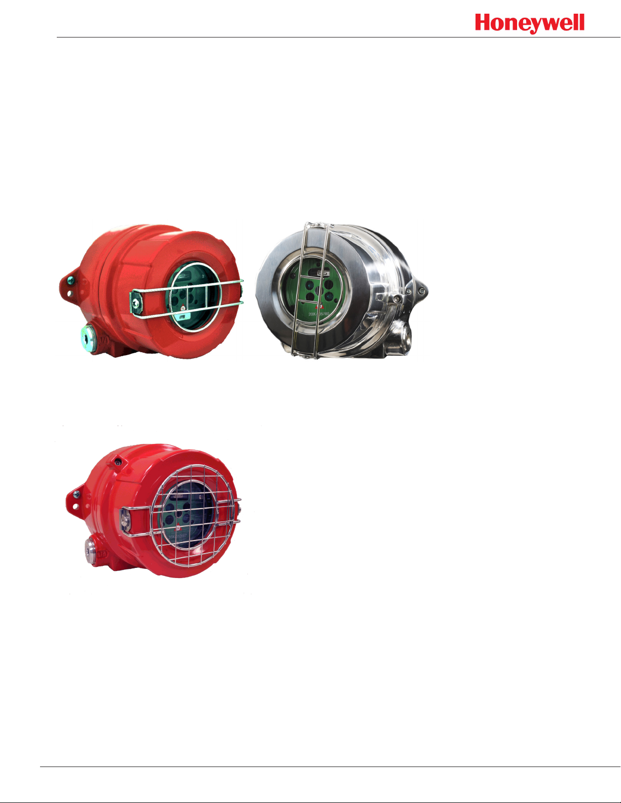
Figure 1. FS20X detectors; aluminum enclosure (left), stainless steel enclosure (right)
The detector is available in a copper-free aluminum enclosure or a 316 stainless
steel enclosure (see Figure 1).
Figure 2. EN54 enclosure
The EN54 version is shown in Figure 2.
The detector’s electro-optical electronics module is a replaceable hard black
enclosure of anodized aluminum that provides ruggedness, handling, ease of
installation, and protection against electromagnetic interference and radio-frequency
interference (EMI/RFI).
8
Page 9

FS20X Fire and Flame Detectors
Principle of Operation
Honeywell Analytics’ Multi-Spectrum, Multi-Spectral, and MultiBand™ infrared (IR)
and ultraviolet (UV) fire and flame detectors are sophisticated, state of the art,
electro-optical digital radiant energy devices that sense the wideband radiant energy
emitted by combustion processes that include the molecular emissions and hot
particulate blackbody emissions in flames. Radiant energy fire detectors respond
much faster to flames and fires at a longer distances than conventional photoelectric
and ionization smoke and heat detectors because a fire radiates energy at the
speed of light. High speed of response is critical for detecting flaming fires in time to
activate suppression systems, close fire doors, etc. Seconds can make the difference
between suppressing a small fire with little or no damage or having a disastrous fire
which overwhelms a suppression system and fails to stop the fire.
Infrared light consists of spectral wavelengths longer than red while ultraviolet light
consists of wavelengths shorter than violet. Much of the IR and UV wavelengths
are invisible to humans. The FS20X™ detector operates from approximately 185.
This includes the visible spectrum, from about 400 to 700 nanometers (0.4 to 0.7
microns.) The visible band is used to discriminate against false alarm sources.
The detector senses radiant energy from both hydrocarbon and non-hydrocarbon
fires. Built-in microprocessors use digital signal processing (DSP) to distinguish
between radiant energy from a real fire and that from a false alarm source.
Honeywell Analytics has developed and refined these complex proprietary and
patented WideBand IR and UV algorithms for 30 years, beginning in 1981. These
patented algorithms perform real-time DSP, and precisely analyze the signals in
high-resolution frequency and time domains. This decision-making process involves
thousands of real-time calculations every second. Honeywell Analytics FSX™
detectors use solid-state high speed quantum sensors (not heat sensors such as
pyroelectric or thermopile) that all respond to the fire’s radiant energy emissions. The
quantum sensors convert the rate of photonic energy directly into analog electrical
signals. These analog signals are converted to high resolution digital values for realtime microprocessor analysis.
The detector microprocessors incorporate random access memory (RAM), readonly memory (ROM), and non-volatile flash memory. When the microprocessors
determine that a fire has been detected, the pre-alarm digital sensor data (FirePic™)
and the event information are recorded in flash memory. Depending on the
configuration, other actions may include activating one or more status LEDs, relays,
a current loop, or sending digital data such as the RS-485 FireBusII™ and Modbus.
If the microprocessor determines, based on internal and “through-the-window”
testing, that the detector is not operating correctly, it records the fault data in flash
memory and activates the fault outputs and the yellow status LED. The digital data in
the detector can easily be accessed with a PC for analysis and record-keeping using
Honeywell Analytics’ Windows®-based PC software and FSIM USB Interface Unit.
9
Page 10

FS20X Fire and Flame Detectors
Features and Benefits
● Selectable sensitivity (four settings)
User can set the detector to any of four detection distances (see “Configuring
the Detector” on page 31).
● Selectable relay options
User-configurable for a variety of dry contact relay interface options (see
“Configuring the Detector” on page 31).
● Selectable 4 – 20 mA output
Source or sink output options (see “Configuring the Detector” on page 31).
● Selectable communications
Configurable for analog or digital communication outputs such as ModBus (see
“Configuring the Detector” on page 31).
● Selectable digital communication address
The user can select a unique 7-bit code (128 addresses, see “Configuring the
Detector” on page 31).
● Lower power consumption
Requires smaller external power supplies and fewer system backup batteries.
● Multiple microprocessors
Reduces the number of discrete detector components, provides larger
programming and memory capacity, and provides redundant self-checking.
● Wider range of applications
Primary applications include long range, fast response to fires such as
acetylene, silane, hydrogen, etc.
● Wider operating temperatures
-40°F to +185°F (-40°C to +85°C) standard
● Built-in automatic “through-the-window” self-test
Monitors window obscuration and checks the operation of the detector’s sensor
array and electro-optical electronics module with built-in IR and UV self-tests.
● Anodized removable aluminum detector module
Rugged, superior protection against EMI/RFI and handling plus simple field
installation and replacement.
● Three bright LEDs (red, yellow, green)
Field status indicators with individual LEDs for alarm, fault, and normal
conditions. Provides superior detector status viewing in bright outdoor
environments (see “Fault Conditions” on page 36).
● Windows-based PC interface
User can perform remote FS20X Detector diagnostics, real-time status,
Real-Time Graphing (RTG™), SnapShot™ data recording, and downloading
FirePics™ with Honeywell Analytics’ exclusive FSIM-2 USB Interface Unit and
easy-to-use Windows-based PC Software.
● Designed to detect both hydrocarbon and non-hydrocarbon fires with a single
FSX™ detector
All fire and flame threats are sensed, not just hydrocarbon fires as with other
triple IR flame detectors.
● FM 3260 approved
Third-party tested and certified for industrial and commercial applications.
● Designed, manufactured, and tested by Honeywell Analytics
Over thirty years of proven fire/flame detection product excellence worldwide.
10
Page 11

FS20X Fire and Flame Detectors
Typical Applications
● Refineries
● Offshore drilling and production platforms
● Petrochemical plants
● Petroleum product pipelines and pumping stations
● Gas compressor buildings
● Gas collection facilities
● Gas processing plants
● Gas turbine enclosures
● Gasoline loading terminals
● LNG storage/distribution
● LPG storage/distribution
● Cogeneration plants
● Crude and product tank farms
● Aerosol filling facilities
● Commercial and military aircraft hangars
● Engine test cells
● Marine engine rooms
● Marine terminals
● Paint and solvent storage
● Power plants
● Product storage terminals
● Rail and truck Loading and Unloading terminals
● Silane gas cabinets
● Silane gas manufacturing
● Hydrogen plants
● Hydrogen storage
● General warehouses
11
Page 12

FS20X Fire and Flame Detectors
Glossary
Term Meaning
algorithm a computational procedure
cycling power turning the detector off and then powering it up again
DSP digital signal processing
end-to-end test the complete system, from detection through suppression, is tested
FireBusII
FirePic
frequency domain signal analysis based on frequency instead of time
IR
Modbus a serial communication protocol
nanometer
NC normally closed (electrical short circuit, by default)
NO normally open (electrical open circuit, by default)
non-volatile flash
memory
micron
RAM random access memory or read and write memory
communications protocol used for transmitting data from a detector to
a Windows-based computer
retrievable pre-fire data storage protocol, used for analysis and pos-
tulation of the cause of a fire
infrared; the wavelengths of light from approximately 700 nanometers
to 1 millimeter
unit of measure equal to one one-billionth (10-9) of a meter; desig-
nated nm
data stored on a chip that is not lost when the detector’s power is
cycled.
unit of measure equal to one one-millionth (10-6) of a meter and 1000
nanometers; designated μm
ROM read-only memory
real-time
self-test
time domain signal analysis based on time
through-the-window
remote testing
UV
wideband a broad range of wavelengths within the infrared spectrum
near-instantaneous analysis and response by a device, usually mea-
sured in milliseconds or microseconds
a test of all of a system’s components, performed automatically on
start-up and periodically during normal operation
testing a detector with a test lamp
ultraviolet; the wavelengths of light from approximately 10 nanome-
ters to 400 nanometers.
12
Page 13
FS20X Fire and Flame Detectors
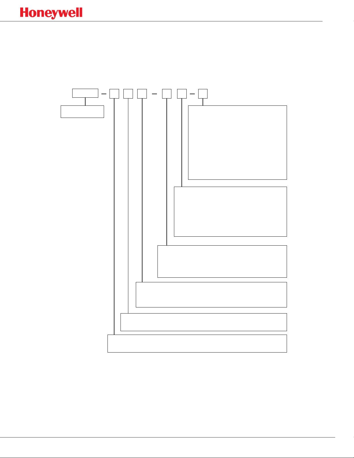
Product Variations
Product variations beyond those field-selectable by the user are available for customers with
specialized needs. This illustration shows how these variations are coded:
Model
Model numbers
FSX20 - IR2UV.UV/IR Self-Test
# # # # # #
Approvals
1 = not available
2 = FM, cFM, ATEX, IECEx (Class I, Divisions 1 & 2)
3 = FM, cFM, ATEX, IECEx (Class I, Zone 1)
4 = INMETRO
5 = Not available
6 = BRE (EN54-10)
7 = CCCF
8 = GOST (CUTR)
Enclosure Types
0 = No Enclosure (Module Only)
1 = Aluminum, ³⁄4 NPT Conduit Entries
2 = 316 Stainless Steel ³⁄4 NPT Conduit Entries
3 = Aluminum, 25 mm Conduit Entries
4 = 316 Stainless Steel 25 mm Conduit Entries
Options
0 = Enclosure Assembly Only (Top & Base)
1 = Detector Module Only
2 = Detector with Enclosure
Outputs
1 = Fire, Auxiliary &Fault Relays / 4-20mA /FireBus II / Modbus
2 = Fire, Auxiliary & Fault Relays / HART 7 over 4-20mA (Source Only)
Application
1 = General Applications
Manufacturer´s Code
2 = Stadard Honeywell Analytics Dtector - Full Window
FS20X-211-22-2
MultiBand IR plus UV detector, general applications with relays, 4-20mA output, FireBus II, 316
stainless steel enclosure with 3/4 NPT conduit entries, Class I, Divisions 1 & 2, Groups B, C & D, Class
II, Groups E, F & G, Class III; Class I, Zone 1 AEx d/Ex d IIC: Ex db IIC, Ex tb IIIC; IR and UV self-tests,
approvals: FM, cFM, ATEX, IECEx, LPCB EN 54-10:200
13
Page 14
FS20X Fire and Flame Detectors
WARNING
!
Test Lamps
Some manufacturers claim that their detectors do not need remote testing with an
external test lamp because it tests itself. Even though Honeywell Analytics detectors
also perform “through-the-window” self-testing, Honeywell Analytics, in compliance
with NFPA 72 codes, has developed portable test lamps for end-to-end remote
testing.
Internal detector testing and window cleanliness testing cannot ensure that a
detector is aimed properly, that its view of the threat area has not been blocked, or
that its alarming circuitry and outputs (i.e., relays, 4-to-20 mA, open collectors, etc.)
are operating properly. Remote test lamps can perform these functions.
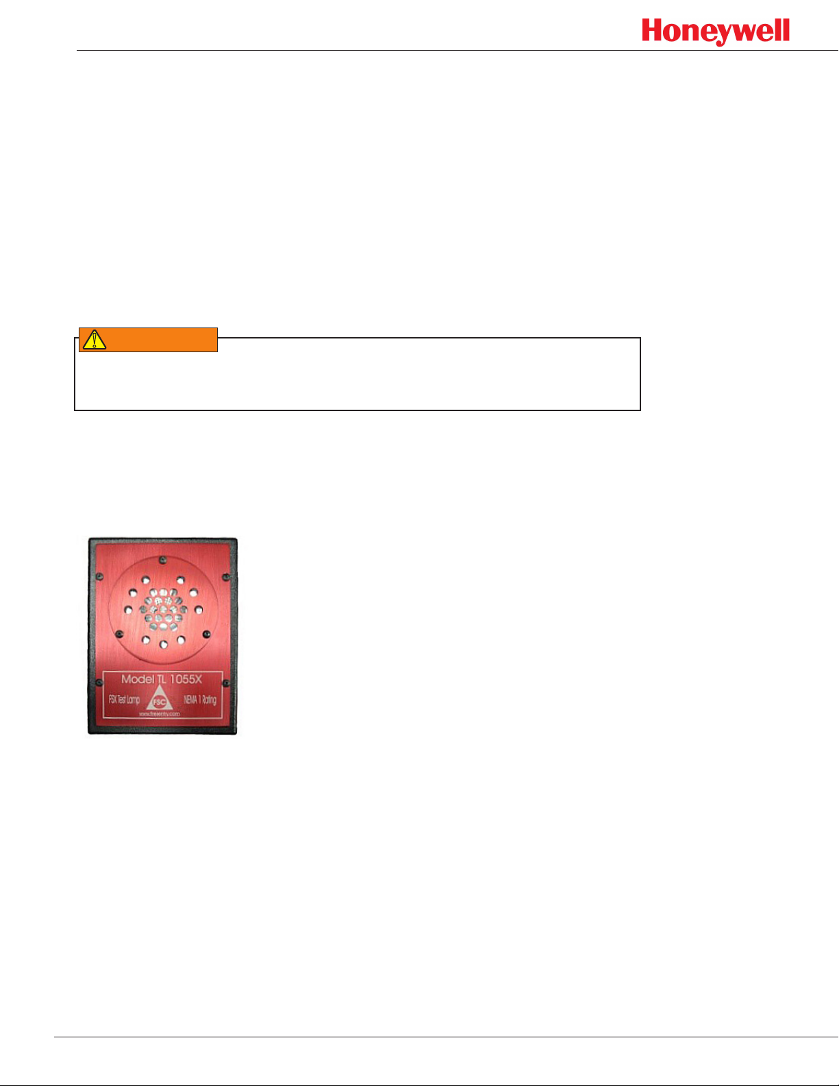
Use test lamp model TL-1055 in non-hazardous locations only. For hazardous
locations, use model TL-2055 as described below.
Test lamp TL-1055
Model TL-1055 is a general purpose NEMA 1 handheld rechargeable test lamp
designed for testing FSX detectors in non-hazardous locations only. The test lamp
(see Figure 3) is supplied with a universal charger (110 VAC and 220 VAC).
Figure 3. TL-1055 handheld test lamp (NEMA 1)
In normal operation, an FS20X detector will alarm to a fully charged TL-1055 test
lamp at a distance of 1 to 25 feet. This complies with NFPA 72 codes.
14
Page 15
FS20X Fire and Flame Detectors
N OT I C E
Test lamp TL-2055
Model TL-2055 is designed for handheld testing of FSX detectors in hazardous
locations. The test lamp, shown in Figure 4, is explosion-proof and carries Class I,
Division 1 approval. It also is supplied with a universal, 110VAC/220VAC charger.
Figure 4. TL-2055 handheld test lamp (Class I, Division 1)
In normal operation, an FS20X detector will alarm to a fully charged TL-2055 test
lamp at a distance of 1 to 25 feet. This complies with NFPA 72 codes.
Test lamps do not represent one-square-foot fires; they demonstrate that a
detector will respond to radiant energy sources within its field of view.
Field of View Restrictor
Certain specialized applications may require a restricted field of view in order to
prevent the detector from alarming to a known (friendly) fire/flame source such as a
flare stack. The model FVR-01 field-of-view restrictor (Figure 5) has been developed
for these unique applications. The restrictor can be easily modified in the field with a
hacksaw. Use of the restrictor has not been certified to the EN54-10 standard.
Figure 5. FOV-01 eld of view restrictor
15
Page 16

FS20X Fire and Flame Detectors
CAUTION
!
Installation
Installation Practices
For installations in a Hazardous Classified Area, consult the National Electrical
Code Handbook, articles 500 through 517 for the proper installation practices. For
locations outside the United States, observe local and regional regulations.
The detector’s metal conduit plug by itself will not provide a weathertight seal.
To maintain the detector’s weatherproof integrity and satisfy local and regional
regulations, apply an approved sealant to the threads.
Before completing the installation, verify that the detector has been configured
correctly for the application. The factory default settings are as follow:
FS20X Settings for SW VER I/F 6175009G and earlier
Description Setting
Alarm relay outputs are non-latching and normally de-energized SW2-1 off SW2-7 off
Detector range/sensitivity is medium SW2-2 off SW2-3 on
Auxiliary relay Verify Time is set to 5 seconds SW2-4 on SW2-5 off
Factory use only SW2-6 off
Fault relay output is normally energized SW2-8 on
Communication is set to FireBusII SW3 is set to position 4
Factory use only SW1-1 through SW1-3 off
Digital communication address is set to 127 SW1-4 through SW1-10 on
FS20X Settings for SW VER I/F 6175009H and later
Description Setting
Alarm relay outputs are non-latching and normally de-energized SW2-1 off SW2-7 off
Detector range/sensitivity is medium SW2-2 off SW2-3 on
Auxiliary relay Verify Time is set to 5 seconds SW2-4 on SW2-5 off
Factory use only SW2-6 off
Fault relay output is normally energized SW2-8 on
Communication is set to FireBusII SW3 is set to position 4
Factory use only SW1-1 & SW1-3 off
8, 12 and 16 mA controls (see table below for details) SW1-2
Digital communication address is set to 127 SW1-4 through SW1-10 on
If the detector’s application requires different settings, refer to “Configuring the
Detector” on page 31 for detailed descriptions.
16
Page 17

FS20X Fire and Flame Detectors
SW1.2 POSITION OF SW1.2
ON
8 mA ENABLED DISABLED
12 mA ENABLED DISABLED
16 mA ENABLED DISABLED
Before applying power to the detector
● Verify that all wire connections are correct (“Detector Connections” on page
24). Each wire must be stripped properly to the correct length, loose wire
strands must be removed, and securely screwed clockwise in the connector.
● When using conduit, ensure that a proper conduit seal (appropriate for the area
classification) has been installed and appropriate measures to prevent moisture
ingress have been taken.
● Consult Honeywell Analytics for dimensional information on flameproof joint
specifications.
● Verify that the detector is securely mounted, its window is clean, and it has an
unobstructed view of the area of coverage (see “Installation Practices” on page
16).
POSITION OF SW1.2
OFF
(This is Defaul Factory Position)
● Shield the detector face from strong light sources when first energized.
The detector is now ready for use. On power-up, the fault relay will change status if
the default setting is used (see “FS20X Default Settings” on page 16).
17
Page 18

FS20X Fire and Flame Detectors
Mounting Instructions
Consider the following guidelines when selecting a detector location:
1. Avoid areas containing radiant energy sources (e.g., radiant heaters, high
intensity lamps, flare stacks, etc.) that would be near the detector’s field of view.
2. Install the detector with the base horizontal. The view angle in this direction is 90°
horizontal as shown in the illustration. (The vertical angle is 80°, 45° below the
center line and 35° above it).
Figure 6. FS20X horizontal eld of view
To comply with the requirements of FM3260, the maximum field of view (FoV)
is the angle at which the device can detect a flame at 50% of the maximum
specified distance. Similarly, to comply with the requirements of EN54-10:2002,
the maximum field of view (FoV) is the angle at which the device can detect a
flame at 70% of the maximum specified distance. To comply with the directional
dependence requirements of EN 54-10:2002, an angle of ±40° (80°) from 0°
(where 0° is the orientation of the detector in the same axes as the flame source)
must not be exceeded.
Model SM4 is a 316 stainless steel swivel mount designed for the FS20X
enclosure. The adapter plate (with the two screw holes) is attached to the base
of the detector (see Figure 7). The mounting plate (four screw holes), can be
secured to a solid surface. Angle adjustments are in 10° increments along either
axis. For single-axis adjustments, the center section need not be installed. Do not
mount the detector facing horizontally or above the horizon. Use at least a 30°
downward angle with the swivel mount. This is especially critical outdoors.
18
Page 19

FS20X Fire and Flame Detectors
Adaptor plate
Mounting plate
Figure 7. SM4 swivel mount
3. Provide the detector an unobstructed view of the threat area. Obstructions
between the detector and a fire may prevent it from being detected.
4. Mount the detector in an area where temperatures will not exceed the specified
operating temperature range (see “Environmental” and “Hazardous Area
Classifications” on page 39).
5. Conduit entries
a. If only one conduit entry is used, install and seal the conduit plug on the
unused entry (¾ in. NPT or 25mm, as shown in Figure 8).
Figure 8. Detector, front view
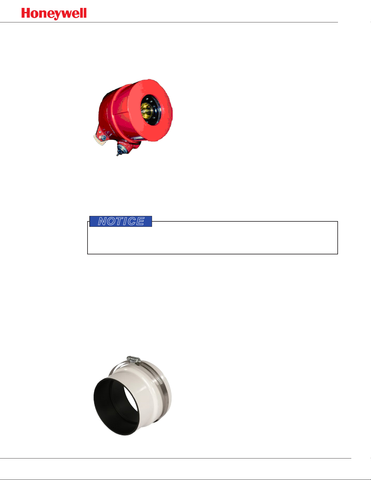
b. Install an approved conduit condensation trap or drain as shown in Figure
9 (if required to meet hazardous area classifications per NFPA 70: National
Electrical Code, latest revision).
Figure 9. Conduit trap
19
Page 20

FS20X Fire and Flame Detectors
CAUTION
!
N OT I C E
Opening the Detector
Use a wrist strap connected to earth ground and follow other static protection
procedures when handling connectors and wiring the electronics module to the
detector.
Do not touch the sensor windows on the front of the detector’s electronics module
(see Figure 10). If necessary, they can be cleaned gently with alcohol and a cotton
swab see “Maintenance” on page <?>.
Figure 10. Electronics module sensor windows
The electronics module must be removed from the for access to the field
connections.
1. Loosen the enclosure’s setscrew (see Figure 11).
Figure 11. FS20X enclosure
20
Page 21

FS20X Fire and Flame Detectors
2. Unscrew and remove the enclosure lid (Figure 12).
Figure 12. Removing the enclosure lid
3. Loosen the electronic module’s three captive screws (Figure 13).
Figure 13. Loosening the captive screws
21
Page 22

FS20X Fire and Flame Detectors
4. Slide the module out of the enclosure base (Figure 14).
Figure 14. Removing the electronics module
Field Connectors
There are two field connection options:
1. A removable ten-pin screw terminal connector (J2) for hardwired relay
applications.
2. A removable six-pin screw terminal connector (J1) for analog output or RS-485
digital communication applications.
The removable connectors provide quicker installation and allow the detector’s
enclosure to be installed before the electronics module.
22
Page 23

FS20X Fire and Flame Detectors
User-selectable Configuration Switches
1. The ten-pin DIP switch (SW1) is used to select a unique digital address (128
choices).
2. The eight-pin DIP switch (SW2) is used to select the detector’s sensitivity and
relay options.
3. The ten-position rotary switch allows selection of the analog and digital
communication protocol.
Figure 15. Electronics module (rear view)
Note: For EN54 units (FS20X-6 suffix), the outer circuit board must be
removed to set the user configurations and then placed back onto
the module after making the adjustments.
23
Page 24

FS20X Fire and Flame Detectors
N OT I C E
Detector Connections
The electronics module has six-pin and ten-pin keyed, removable connectors with
female screw terminal plugs. These connect to the two respective male connectors
with analog, digital, and relay interfaces (see Figure 16). Use the ten-pin plug (J2)
and connector for relay configurations. For digital and analog configurations, use the
six-pin plug (J1) and connector.
J2 Connector J1 Connector
Pin Connection Pin Connection
1 Auxiliary NC 1 DC return
2 Auxiliary NO 2 RS-485-A
3 Auxiliary COM 3 RS-485-B
4 Alarm NC 4 +24 VDC
5 Alarm NO 5 4-20mA source
6 Alarm COM 6 4-20mA sink
7 Fault NO
8 Fault COM
9 +24 VDC
10 DC return
Figure 16. Electronics module, rear view (contacts shown with no power applied)
Do not open the electronics module as this will void all warranties.
Avoid wire splices whenever possible. Good wiring practices simplify installation,
improve reliability, and facilitate maintenance. If wire splices are necessary, solder
and properly insulate them.
24
Page 25

FS20X Fire and Flame Detectors
Wiring and Terminal Connections
Figure 17. Typical wiring for 4-20 mA (sourcing) analog output
Figure 18. Typical wiring for 4-20 mA (sinking) analog output
Notes:
1. The cable shield must be grounded at one end only, at the control panel.
2. Coil and tape the cable shield at the detector end.
3. Set rotary switch SW3 to position 1 for source current wiring or to position 0 for
sink current wiring.
25
Page 26

FS20X Fire and Flame Detectors
Figure 19. Typical relay output wiring for monitoring separate alarm and fault contacts
Figure 20. Typical relay output wiring for monitoring alarm and fault contacts on a single two-wire input
Notes:
1. The cable shield must be earth grounded at one end only, at the control panel.
Coil and tape the cable shield at the detector end.
2. The alarm relay contacts are shown with no power applied. The alarm relay is
de-energized during normal operation and with no alarm. This relay will energize
during alarm conditions.
3. Fault relay contacts are also shown with no power applied. During normal
operation and with no fault, this relay will energize and the N.O.contacts will
close.
4. Install an E.O.L. device as required and supplied by the fire alarm panel.
26
Page 27

FS20X Fire and Flame Detectors
Figure 21. Recommended wiring congurations
Changing Detector Settings
1. Verify that the external 24 VDC power is turned off before connecting the
detector.
2. After applying 24 VDC power, after tests (i.e., butane lighter, FSC test lamp, or
test fires), or after resetting the detector, wait at least thirty seconds to allow its
sensors to normalize to the spectral background conditions.
3. To activate SW1/SW2/SW3 setting changes, reset the detector by cycling the
power.
4. For applications requiring analog/digital communications, refer to “Configuring
the Detector” on page 31.
27
Page 28

FS20X Fire and Flame Detectors
CAUTION
!
Start-up and commissioning
During start-up and commissioning, disable all outputs from the detector to any
control panels or other control devices.
Testing the detector
After the detector is powered, thoroughly test is using a hand-held test lamp to
ensure the detector has an unobstructed view of the threat area.
Honeywell Analytics FSX detectors feature automatic electronics and internal
software testing every three seconds. This includes a through-the-window test that
verifies the cleanliness of the viewing window. As with all other optical fire and flame
detectors, this does not constitute a fully functional “end to end” test. Self-tests can
only partially check and test the operational readiness of a detector. In order to
thoroughly test the readiness of any fire or flame detector (without starting a real
fire, which is not permitted in hazardous areas), the detector must be tested with a
test lamp. This is the only safe and non-hazardous method to test any detector’s
sensors, internal electronics, alarm activation software, viewing window cleanliness,
terminal wiring integrity, relay activation, and the functionality of all of its outputs.
Since most detectors are installed in fire alarm systems, this is the only method to
test a complete system, ensuring that all of the system wiring and the control panel
are properly installed.
Additionally, using an external test lamp eliminates these conditions:
● The window being covered (with, for example, paint overspray, hanging
garments, etc.)
● The detector being improperly positioned or oriented
● The detector’s line of sight being blocked (i.e., by recently installed air ducts
or pipes, storage boxes, vehicles, etc.) preventing the threat area from being
fully protected. Optical fire and flame detectors are line-of-sight devices so they
must be properly positioned and oriented with unobstructed views of their threat
areas.
28
Page 29

FS20X Fire and Flame Detectors
To test the full functionality of the detector, use test lamp model TL-1055 or TL2055 in the manner prescribed in “Test Lamps” on page 15. These are the only
test lamps that can activate FSX detectors. Do not use them with other Honeywell
Analytics detectors or with those of other manufacturers.
1. Disable the outputs (a full functional test includes activating the alarm outputs).
2. Aim the test lamp at the front of the detector (within a distance of about 1 to 25
feet and on-axis as much as possible).
3. Press and hold the test lamp’s pushbutton.
4. While watching the alarm LED on the face of the detector, slowly move the test
lamp’s boresight to ensure that the detector receives its full intensity. Practicing
this technique will help optimize the testing of other detectors. The LED will
illuminate, usually within three to ten seconds. The alarm relay outputs will also
activate and the 4-20 mA analog output will increase to 16mA (±0.6mA), then
20mA (±0.6mA) after the Verify Time is exceeded.
5. If the detector does not respond within thirty seconds:
a. Verify that the test lamp has has been charged sufficiently.
b. Verify that the test-lamp-to-detector distance is between one and twenty-five
feet.
c. Verify that the testing technique described above has been followed. If the
detector still does not respond, contact Honeywell Analytics.
29
Page 30

FS20X Fire and Flame Detectors
Drawings
Dimensions
Figure 22. FS20X dimensions
Figure 23. SM4 outline and dimensions
30
Page 31

FS20X Fire and Flame Detectors
N OT I C E
Operation
Configuring the Detector
To activate changes to the settings using SW1, SW2, or SW3, reset the detector
by cycling the 24 VDC power.
DIP Switch SW1
The digital address for RS-485 communication can be set using positions 4 through
10 on DIP switch SW1, shown in Figure 24. (Do not change switch positions 1, 2, or
3 on SW1; they are for factory use only.)
Figure 24. Ten-position DIP switch SW1.
SW1 Configuration
Digital Address 1 2 3 4 5 6 7 8 9 10
000 off off off off off off off off off off
001 off off off off off off off off off on
002 off off off off off off off off on off
003 off off off off off off off off on on
124 off off off on on on on on off off
125 off off off on on on on on off on
126 off off off on on on on on on off
127 (default) off off off on on on on on on on
31
Page 32

FS20X Fire and Flame Detectors
DIP Switch SW2
Figure 25. Eight-position DIP switch SW2
SW2 Configuration
Default settings are highlighted in grey.
Alarm Relay SW2-1
Latching on
Non-latching off
SW2
ON
Sensitivity Levels SW2-2
Very High (4) on on
High (3)
Medium (2)
Low (1)* off off
*The low sensitivity range is not compliant
with the requirements of EN 54-10:2002.
Auxiliary Relay SW2-4
No Verify Time
5 Sec. Verify Time
10 Sec. Verify Time
20 Sec. Verify Time
on
off
on on
on
off
off off
SW2-3
off
SW2-5
off
on
off
off
on
1 2 3 4 5 6 7 8
Factory Use Only
SW2-6
off
OFF
Fault Relay SW2-8
Energized on
De-energized** off
**If the fault relay is de-energized,
the detector will not report loss
of power faults.
Alarm Relay SW2-7
Energized on
De-energized off
32
Page 33

FS20X Fire and Flame Detectors
Rotary Switch SW3
Figure 26. Ten-position rotary switch SW3.
The detector has a variety of analog and RS-485 digital communication options. Analog and digital
outputs are available in addition to relay outputs. Select from two analog outputs or two digital outputs
using the ten-position rotary switch SW3. When ‘4-20mA sink’ or ‘4-20mA source’ are selected, the
default RS-485 protocol is FireBusII. When ‘RS-485 FireBusII’ or ‘RS-485 Modbus’ are selected, the
default analog output is 4-20mA source. FireBusII (position 4) is the default setting (highlighted in grey
in the table below). Use Figure 26 and this table to configure SW3:
SW3 Configuration
Position Output Selection
0 4-20 mA sink
1 4-20 mA source
2 RS-485 Modbus
3 Factory use only
4 RS-485 FireBusII
5 Factory use only
6 Factory use only
7 Factory use only
8 Factory use only
9 Factory use only
33
Page 34

FS20X Fire and Flame Detectors
LED Status Indicators
The detector status is indicated by three LEDs:
● Green
● blinking (flashing) once every ten seconds indicates a normal, safe operational
condition (i.e., no faults or alarms).
● off when no external input power is applied to the detector.
● Yellow
● blinking (flashing) when the window is dirty
● on steadily for all other fault conditions
● “Red flashes while FirePic is being stored”New Bullet:
● “Red turns on when a fire is alarmed”
Normal Operation
In normal operation1 the green LED, shown in Figure 27, blinks every ten seconds. If
one of the 4-20 mA options is selected (see “SW1 Configuration” on page 31), the
current, sink, or source will be 4.0 mA ±0.6 mA. Only the current source mode has
been certified to the EN54-10 standard.
Figure 27. Green LED location
1 Normal operation is dened as the detector with 24 VDC applied without alarm or fault conditions.
34
Page 35

FS20X Fire and Flame Detectors
Alarm Condition
When an alarm condition occurs, the red LED shown in Figure 28 will turn on. The
factory setting for the auxiliary relay is 5 seconds.
Figure 28. Red LED location
Alarm condition outputs
● Alarm Relay activation
● Auxiliary Relay activation
2
only one active alarm output from this group:
● 4-20 mA (sink 16 mA) Alarm Output
● 4-20 mA (source 16 mA) Alarm Output
● 4-20 mA (sink 20 mA) Auxiliary Output
● 4-20 mA (source 20 mA) Auxiliary Output
only one active alarm from this group:
● RS-485 FireBusII Alarm Notification
● RS-485 ModBus Alarm Notification
2 veried alarm output
35
Page 36

FS20X Fire and Flame Detectors
Fault Conditions
When a fault (trouble) condition occurs, the yellow LED will illuminate. See Figure
3-6 for the location of the Yellow LED.
Figure 29. Yellow LED location
Fault condition output
Fault relay activation
4-20mA output
4-20 mA (sink) output
3
2 mA (self-test/window obscuration fault)
0 mA (all other faults)
4-20 mA (source) output
4
2 mA (self-test/window obscuration fault)
0 mA (all other faults)
R2-485 output
RS485 FireBusII fault notification
RS-485 Modbus fault notification
4
4
Causes of fault conditions:
● Under voltage input power (<18 VDC).
● Over voltage input power (>32 VDC).
● Over temperature (>85 °C or 185 °F for the standard version).
● Under temperature (<-40 °C or -40 °F for the standard version).
● One or more microprocessor failures.
● One or more relay coil failures.
● Communication fault.
3 only one active fault output from these three
36
Page 37

FS20X Fire and Flame Detectors
WARNING
!
● Electronic self-test failure.
● Dirty window (flashing yellow LED)
Maintenance
After the detector is installed and commissioned, little maintenance is required.
However, a test of the entire fire detection system should be performed periodically,
depending on the application. Additionally, semi-annual or quarterly testing should be
performed with the appropriate Honeywell Analytics test lamp (TL-1055 or TL-2055)
to ensure the integrity of the system.
Establish a periodic cleaning schedule. Some industrial environments may require
more frequent cleaning of the detector’s window than others.
Clean the detector’s window any time it is dirty or contaminated, every time the
enclosure lid is handled, if the detector fails the built-in test, or if the detector fails an
end-to-end test with the test lamp. If necessary, clean the detector module sensors
whenever the detector has been disassembled.
Use a blast of clean air or an oil-free cloth to clean the enclosure window (oil
degrades the performance of UV detectors). Do not use commercial or siliconebased window cleaning products; they also will degrade the detector’s performance.
Occassional use of a solvent such as 6% isopropyl alcohol is acceptable. No
disassembly of the detector is required for this.
To avoid electrostatic discharge, wipe the enclosure only with a damp cloth.
37
Page 38

FS20X Fire and Flame Detectors
Specifications
Mechanical
Description Value
Enclosure Materials
Assembly 4.35 in. (110.49 mm) H × 4.81 in. (122.24 mm) Dia
Dimensions
Weight
Enclosure Rating IP66, NEMA 4, NEMA 4X
Vibration meets or exceeds Mil Spec 810C, Method 514.2, Curve AW
Mounting holes ¼ in. (6.35 mm) Dia, 5½ in. (139.70 mm) center-to-center
Conduit entries Two ¾ in. NPT or two 25 mm
Aluminum 3 lbs. 11 oz. (1.7 kg) approximately
Stainless steel 7 lbs. 7 oz. (3.4 kg) approximately
copper-free aluminum (red)
316 stainless steel
Electrical
Description Value
Input voltage range 18 VDC to 32 VDC
Normal operation current 85 mA (nominal), 175 mA (nominal with heater1)
Maximum fire alarm current 135 mA (maximum), 220 mA (maximum with heater1)
Relay contact rating 1 Amp @ 24 VDC resistive
0.0 to 20.0 mA (Non-isolated source or sink, user selectable)
0.0 mA (<0.6 mA) = Fault
2.0 mA (±0.6 mA) = Dirty window
Analog current output
Screw terminal wire sizes 12 AWG to 22 AWG (2.50 mm to 0.762 mm; use stranded
1
The heater circuit turns on only when the temperature drops below 0° F (-17° C).
2
400 ohms maximum load (loop resistance}
3
If the “verify time” is not zero, the alarm level = 16 mA and the verify level = 20 mA. If the verify time
is zero, alarm level = 20 mA and the verify level = 20 mA.
2, 3
4.0 mA (±0.6 mA) = Normal, safe (no fault, no fire)
8.0 mA (±0.6 mA) = Background IR
12.0 mA (±0.6 mA) = Background UV
16.0 mA (±0.6 mA) = Fire alarm
20.0 mA (±0.6 mA) = Verified fire alarm
conductors, not solid core)
38
Page 39

Environmental
Description Value
FS20X Fire and Flame Detectors
Operating Temperature,
Standard
Operating Humidity Range 0 to 95% RH, 100% RH condensing for short periods of time
Storage Temperature -67° F to +221° F (-55° C to +105° C)
-40° F to +185° F (-40° C to +85° C)
Performance
Description Value
Field of View
Sensitivity 1 sq. ft. heptane fire at 200 feet (± 45° from axis)
Speed of Response typically 2 to 5 seconds
Spectral Sensitivity ~0.185 to 0.26 microns and 0.4 microns to 3.5 microns
Wire Temperature Rating
cone of view is 90° horizontal and 80° vertical (35° above
the center line and 45° below it)
must be rated at least 10°C above the rated service temperature
(120°C for T4 applications, 85°C for T5 applications)
Hazardous Area Classifications
(See “Hazardous Location Detector Markings” on page 42)
Description
Class I, Division 1, Groups A, B, C & D
Class II, Division 1 Groups E, F & G Class I, Zone 1, AEx d/ Ex d IIC
Class III Ex db IIC, Ex tb IIIC
T4: Ta = -40°C to +110°C T4: Ta = -40°C to +110°C
T5: Ta = -40°C to +75°C T5: Ta = -40°C to +75°C
T6: Ta = -40°C to +60°C T6: Ta = -40°C to +60°C
Performance Certifications
(See “Hazardous Location Detector Markings” on page 42)
Agency Standard Certificate Notes
LPCB EN 54-10:2002 +A1:2005 1175a/01
CPR EN 54-10:2002 +A1:2005 0832-CPR-F0515
Sensitivity settings: Very
High, High, Medium
EN 54-10 Class 1
39
Page 40

FS20X Fire and Flame Detectors
Additional Performance Specifications
Flame Response Sensitivity
This table provides typical response times for various fuels:
MultiBand IR plus UV Detector
Location Fuel Fire Size
Acetylene 12 in (0.30 m) plume - medium flame 35/10.7 2
Acetylene 10 - 12 in (0.25 - 0.30 m) plume - lazy flame 40/12.2 < 2
Diesel 6 in X 6 in (15.2 cm X 15.2 cm) 87/26.5 < 3
Ethanol 12 in X 12 in (0.3 m X 0.3 m) 50/15.2 < 3
Hydrogen 3/8 in dia. (9.5 mm) orifice, 32 in (0.8 m) plume 85/25.9 < 3
Indoors
Outdoors
IPA 6 in X 6 in (15.2 cm X 15.2 cm) 87/26.5 < 3
JP4 6 in X 6 in (15.2 cm X 15.2 cm) 75/22.9 < 3
JP8 6 in X 6 in (15.2 cm X 15.2 cm) 87/26.5 3
Methane 3/8 in dia. (9.5 mm) orifice, 32 in (0.8 m) plume 70/21.3 < 3
Methanol 12 in X 12 in (0.3 m X 0.3 m) 40/12.2 < 3
n-Heptane 6 in X 6 in (15.2 cm X 15.2 cm) 87/26.5 < 3
Silane 1/32 dia (0.8 mm) orifice, 12 in (0.3 m) plume 30/9.1 < 2
Acetylene 12 - 16 in (0.30 - 0.41 m) plume - large flame 100/30.5 < 3
Acetylene 12 in (0.30 m) plume - medium flame 100/30.5 < 4
Acetylene 10 - 12 in (0.25 - 0.30 m) plume - lazy flame 90/27.4 < 3
Diesel 12 in X 12 in (0.3 m X 0.3 m) 150/45.7 4
Ethanol 12 in X 12 in (0.3 m X 0.3 m) 60/18.3 < 3
Hydrogen 3/8 in dia. (9.5 mm) orifice, 32 in (0.8 m) plume 75/22.9 < 3
IPA 12 in X 12 in (0.3 m X 0.3 m) 150/45.7 < 3
JP4 12 in X 12 in (0.3 m X 0.3 m) 150/45.7 < 4
JP8 12 in X 12 in (0.3 m X 0.3 m) 150/45.7 < 4
Methane 3/8 in dia. (9.5 mm) orifice, 32 in (0.8 m) plume 60/18.3 2
Methanol 12 in X 12 in (0.3 m X 0.3 m) 40/12.2 < 2
n-Heptane 12 in X 12 in (0.3 m X 0.3 m) 200/61.0 < 4
Silane 1/32 dia (0.8 mm) orifice, 12 in (0.3 m) plume 50/15.2 < 3
Distance
(ft/m)
Typical
Response
Time
(seconds)
40
Page 41

FS20X Fire and Flame Detectors
False Alarm Immunity
The second column in this table shows the minimum distance at which a detector
exposed to various false fire sources did not alarm or show any signs of instability.
The third column shows the sensitivity to a one-foot square n-Heptane reference fire
in the presence of those false fire sources.
False Alarm Immunity
False Fire Source
Direct Sunlight No alarm 50 ft (15.24 m)
Modulated Sunlight No alarm 25 ft (7.62 m)
Modulated Arcwelding 9 ft 9 in (3 m)
Continuous Arcwelding 9 ft 9 in (3 m)
Resistive Electric Heater 1 ft (30.48 cm)
Flourescent Lamp 1 ft (30.48 cm)
Halogen Lamp 1 ft (30.48 cm)
Sodium Vapor Lamp 1 ft (30.48 cm)
Pelican Flashlight 1 ft (30.48 cm)
Incandescent Lamp 1 ft (30.48 cm)
Minimum Distance
with No Alarm
Sensitivity to Reference Fire
Source at 30 ft (9.14 m)
Fire at 30 ft (9.14 m)
Source at 30 ft (9.14 m)
Fire at 30 ft (9.14 m)
Source at 3 ft (91.44 cm)
Fire at 200 ft (60.96 m)
Source at 3 ft (91.44 cm)
Fire at 200 ft (60.96 m)
Source at 3 ft (91.44 cm)
Fire at 200 ft (60.96 m)
Source at 3 ft (91.44 cm)
Fire at 200 ft (60.96 m)
Source at 3 ft (91.44 cm)
Fire at 200 ft (60.96 m)
Source at 3 ft (91.44 cm)
Fire at 200 ft (60.96 m)
41
Page 42

FS20X Fire and Flame Detectors
Hazardous Location Detector Markings
Class I, Division 1, Groups A, B, C & D; Class II, Division 1 Groups E, F & G; Class
III; Class I, Zone 1 AEx d /Ex d IIC Hazardous Locations.
ATEX IECEx Certification Class I, Zone 1, Ex db IIC (T4-T6) and Ex tb IIIC (T4-T6).
ATEX Certification FM14ATEX0058X
IECEx Certification FMG 14.0027X
Ex db IIC T6….T4 Gb
Ex tb IIIC T135C Db IP66
II 2 G Ex db IIC T6…T4 Gb
II 2 Ex tb IIIC T135C IP66
FS20X Configurations
Part No. Material
LB-6093-037
LB-6093-038 0.020' 316 stainless steel Polished Black 150
LB-6093-039 0.020' Al 1100-Hl4 Black White 150
LB-6093-040
0.020' Al 1100-Hl4 Black White 150
0.020' 316 stainless steel Polished Black 150
Background
Color
Text
Color
FS20X Label Configurations
Part No.
LB-6095-001 FS20X
Model
No.
Description Material
Label, FS20X, ss, with
FM/Canada/US ATEX,
IECEX approval
0.020” 316
stainless
steel
IR/UV
Type
WideBand
IRTM/UV
LPCB No.
CPR No.
1175a/01
0832-CPR-F0515
mA T4 T5 T6
-40 °C
to
+110 °C
-40 °C
to
+110 °C
-40 °C
to
+110 °C
-40 °C
to
+110 °C
Back-
ground
Color
Matte Black 150
Text
Color
-40 °C
to
+75 °C
-40 °C
to
+75 °C
-40 °C
to
+75 °C
-40 °C
to
+75 °C
-40 °C
to
+60 °C
-40 °C
to
+60 °C
-40 °C
to
+60 °C
-40 °C
to
+60 °C
mA T4 T5 T6
-40 °C
-40 °C
to
+110 °C
to
+75 °C
-40 °C
to
+60 °C
42
Page 43

FS20X Fire and Flame Detectors
Warranty
Honeywell Analytics warrants the FS20X fire and flame detector against defects
in material and workmanship under normal use and service for a period of three
years from the date of shipment. Honeywell Analytics, at its option, will repair or
replace, at no charge detectors found to be defective during the warranty period
they are returned in accordance with the terms of this warranty. Replaced parts are
warrantied for the balance of the original applicable warranty period. All replaced
parts become the property of Honeywell Analytics. This express limited warranty is
extended by Honeywell Analytics to the original purchaser only and is not assignable
or transferable to any other party. This is the complete warranty for FS20X fire
and flame detectors. Honeywell Analytics assumes no obligations or liability for
additions or modifications to this warranty unless made in writing and signed by an
officer of Honeywell Analytics. Honeywell Analytics does not warrant the installation,
maintenance, or service of its products. Honeywell Analytics is not responsible for
ancillary equipment not furnished by Honeywell Analytics, which is attached to or
used in connection with its products or for operation of the products with ancillary
equipment and all such equipment if expressly excluded from this warranty. This
warranty sets forth the full extent of Honeywell Analytics’ responsibility regarding the
detector’s repair or replacement at Honeywell Analytics’ options and is the exclusive
remedy.
This warranty is given in lieu of all other express warranties and implied warranties,
including without limitation implied warranties of merchantability and fitness for a
particular purpose and is limited to the duration of this limited warranty. In no event
shall Honeywell Analytics be liable for damages in excess of the purchased price of
the product, for any loss of use, loss of time, inconvenience, commercial loss, lost
profits or savings, or other incidental, special, or consequential damages arising from
or in connection with the use or inability to use the detector, to the full extent such
may be disclaimed by law.
This warranty does not cover:
1. Defects or damage resulting from use of the detector in other than its normal and
customary manner.
2. Defects or damage from misuse, accident, or neglect.
3. Defects or damage from improper testing, operation, maintenance, installation,
alteration, modification, or adjustment.
4. Detectors subjected to unauthorized modifications, disassemblies, or repairs
including, without limitation, the addition to the detector of non-Honeywell
Analytics equipment which adversely affects the performance of the detector to
interfere with Honeywell Analytics’ normal warranty inspection and testing of the
detector to verify any warranty claim.
5. Detectors whose serial numbers have been removed or made illegible
6. Freight costs to the repair facility.
43
Page 44

FS20X Fire and Flame Detectors
7. Detectors which, due to unauthorized alteration of their software or firmware, do
not function in accordance with Honeywell Analytics’ specifications.
8. Cosmetic damage to detectors’ surfaces that do not affect their operation.
9. Normal and customary wear and tear.
Laws in the United States and other countries preserve for Honeywell Analytics
certain exclusive rights for copyrighted Honeywell Analytics software and firmware,
such as the exclusive rights to reproduce in copies and distribute copies of such
software or firmware. Honeywell Analytics software or firmware may be used only
in the detectors in which the software or firmware was originally installed. Such
software or firmware may not be replaced, copied, distributed, modified in any way,
or used to produce any derivative thereof. No other use including, without limitation,
alteration, modification, reproduction, distribution, or reverse engineering of such
Honeywell Analytics software or firmware or exercise or rights in such Honeywell
Analytics software/firmware is permitted. No license is granted by implication,
estoppel, or otherwise under Honeywell Analytics patent rights or copyrights.
44
Page 45

FS20X Fire and Flame Detectors
Index
A
adapter plate 18
alarm conditions 35
alcohol, isopropyl 37
analog output 22
sinking 25
sourcing 25
angle adjustments, mounting 18
applications, typical 11
B
base, SM4 30
C
cable shield 25, 26
captive screws 21
caution 6
cleaning 37
codes, product variation 13
commissioning 28
communication protocol
analog 23
digital 23
conduit 17
condensation drain 19
condensation trap 19
plug 19
congurations 42
label 42
switches 23
conguring the detector 31
connector
J2 24
J1 24
removable 24
contacting Honeywell Analytics
7
contacts
alarm relay 26
fault relay 26
control devices 28
control panel 25, 28
D
Danger notices 6
default settings 16, 17
detector
connections 24
opening 20
sensitivity 23
digital address 23
dimensions 30
DIP switch
SW1 23, 31
SW2 23, 32
SW2 conguration 32
distance, re to detector 41
drawings 30
DSP 9
E
earth ground 20
electronics module 20, 23, 24
electrostatic discharge 37
EN54-10 15, 34
EN 54-10:2002 18
enclosure 20
base 22
lid 21
types 8
window, cleaning 37
F
false alarm 9
false alarm immunity 41
fault
conditions, causes 36
relay 17, 36
features and benets 10
eld connections 20, 22
eld of view 18
eld of view restrictor 15
FireBusII 33, 36
re sources, false 41
ameproof 17
fuels 40
G
glossary 12
grounding 25, 26
H
hazardous area classications
39
housing 20
I
infrared light 9
installation 16
interface
analog 24
digital 24
relay 24
introduction 5
L
LEDs
alarm 29
green 34
red 34
status indicator 38
yellow 34
location 18
M
maintenance 37
markings, detector 42
Modbus 36
model numbers 13
mounting 17
N
National Electrical Code 16, 19
NFPA 70 19
NFPA 72 15
notices 6
O
operation 31
output
alarm conditions 35
analog 33
digital 33
fault condition 36
relay 33
overview 8
45
Page 46

FS20X Fire and Flame Detectors
P
performance certications
39
power-up 17
principle of operation 5, 7,
9, 13
product variations 13
R
radiant energy sources 18
reference re 41
relay
hardwired 22
options 23
removable connectors 22
resetting the detector 31
rotary switch 23, 25, 33
RS-485 22, 31, 33
S
safety 6
screws, captive 21
sealant, thread 16
self-test 36
sensitivity 40, 41
sensor windows, cleaning
20
setscrew 20
settings, detector 28
specications
electrical 38
environmental 39
mechanical 38
performance 39, 40
spectrum, visible 9
start-up 28
static protection proce-
dures 20
status indicator, LED 34
switch
SW1 31
SW2 31
SW3 31
swivel mount 18
symbols 6
T
terminal connections 25
terminal connector
J1 22
J2 22
terminals 27
testing 28
quarterly 37
semi-annual 37
system 37
test lamp 14, 28, 29, 37
TL-1055 14
TL-2055 14
trademarks 5
troubleshooting, see fault
conditions, causes
U
ultraviolet 9, 13
UV see ultraviolet
V
view angle 18
W
warnings 6
warranty 24, 43
wavelengths 9
weatherproof integrity 16
weathertight seal 16
wiring 17, 25, 27
congurations, recom-
mended 27
relay output 26
wrist strap 20
46
Page 47

Page 48

1998M0902
Revision F
© 2017-2018 Honeywell Analytics
 Loading...