

Page 1
F300E
Electronic Air Cleaner
PRODUCT DATA
FEATURES
• Available in four sizes to fit most ducts; adapts to
airflow from either side.
• Capacity varies from 1200 cfm (2040 m3/hr) to
2000 cfm (3400 m
• Solid state power supply is self-regulating and
maintains peak efficiency during a wide range of
cell dirt loading conditions.
• Pressure drop is approximately equal to that of a
regular fiberglass filter.
• Optional W8600F Air Cleaner Monitor indicates air
cleaner performance, reminds homeowner when a
cell and prefilter wash is due, and when to check
the system.
• Optional wireless W8600A AIRWATCH™ LCD
indicator provides reminder when air cleaner
electronic cells need washing, as well as reminder
when UV lamps need replacing and when humidifier
pad needs replacing.
• Galvanized cabinet protects against rust.
• Neon light next to on-off switch tells if air cleaner is
powered and if high voltage is present.
• Prefilter screens protect cells from large dirt
particles.
3
/hr), depending on size.
APPLICATION
The F300E Electronic Air Cleaner is mounted in the return
air duct of a forced air heating, cooling, or ventilating system.
It captures a significant amount of the airborne particles 0.3
microns and larger from the air circulated through it.
® U.S. Registered Trademark
Copyright © 2000 Honeywell • All Rights Reserved
Contents
Application ........................................................................ 1
Features............................................................................ 1
Specifications.................................................................... 2
Ordering Information......................................................... 2
Planning the Installation ................................................... 4
Installation......................................................................... 7
Operation .......................................................................... 13
Checkout........................................................................... 13
Service.............................................................................. 13
Replacement Parts/Exploded View .................................. 18
Electrical T roub leshooting................................................. 20
68-0240-1
Page 2
F300E ELECTRONIC AIR CLEANER
SPECIFICATIONS
IMPORTANT
The specifications given in this publication do not
include normal manufacturing tolerances.
Therefore, this unit may not exactly match the listed
specifications. This product is tested and calibrated
under closely controlled conditions, and some
minor differences in performance can be expected if
those conditions are changed.
Model:
Electronic Air Cleaner: Includes cabinet, access door, solid
state power supply, two electronic cells and two prefilters.
Electrical Ratings:
Voltage and Frequency: 120V, 60 Hz. Can be converted in
the field to 240V, 60 Hz or 220/240V,
50 Hz with the 203365A Conversion Kit.
Power Consumption: 36W maximum.
Current Draw: See Table 1.
Ionizer V oltage: 8150 Vdc.
Collector V oltage: 4075 Vdc.
Capacity, Efficiency, Pressure Dr op:
See Fig. 1, for capacity, pressure drop and ASHRAE dust
spot efficiencies.
Fractional Efficiency:
70% efficient on 0.3 micron particles at 500 fpm.
90% efficient on 1.0 micron particles at 500 fpm.
99% efficient on 10.0 micron particles at 500 fpm.
Temperature Ratings:
Operating Ambient: 40° to 125°F (4° to 52°C).
Temperature of Airflow Through Cells: 40° to 125°F
(4° to 52°C).
Maximum Cell Washing Temperature: 220°F (140°C).
Storage and Shipping Ambient: Minus 40°F to plus 140°F
(minus 40°C to plus 60°C).
Mounting:
Mounts in the return air duct of a forced air heating, cooling,
or ventilating system. Mount upstream from the atomizing
humidifier. See the Planning the Installation section.
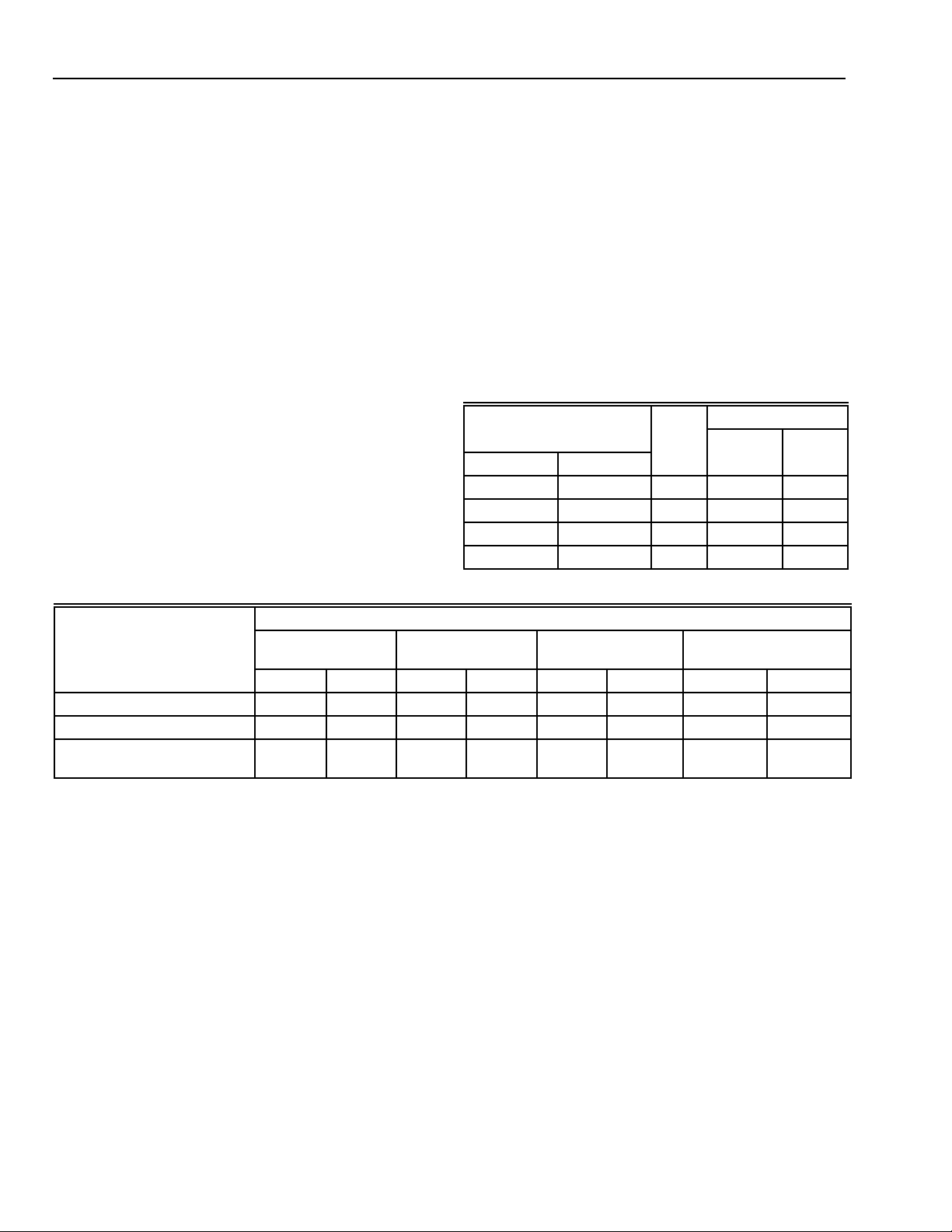
Table 1. Current Draw.
Max. Current (A)
Size
in. mm
16 x 20 406 x 508 2 0.4 0.2
16 x 25 406 x 635 2 0.4 0.2
20 x 20 508 x 508 2 0.4 0.2
20 x 25 508 x 635 2 0.4 0.2
No. 220/
Cells
120V
240V
Table 2. Shipping and Installation Weight.
Weight
16 x 20 in.
(406 x 508 mm)
lb kg lb kg lb kg lb kg
Electronic Cell (Each) 5 2.25 6 2.7 6-3/16 2.8 7-1/2 3.4
Shipping Weight 30 13.6 33 15.0 33 15.0 38 17.2
Installed Weight
(Cells Included)
26 11.6 28 12.7 29 13.2 33 15.0
16 x 25 in.
(406 x 635 mm)
20 x 20 in.
(508 x 508 mm)
20 x 25 in.
(508 x 635 mm)
ORDERING INFORMATION
When purchasing replacement and modernization products from your TRADELINE® wholesaler or distributor, refer to the
TRADELINE® Catalog or price sheets for complete ordering number, or specify
1. Order number.
2. Voltage and frequency.
3. Dimensions: 16 x 20, 16 x 25, 20 x 20, or 20 x 25 in. (406 x 508, 406 x 635, 508 x 508, or 508 x 635 mm).
4. Conversion kit for changing two cell 120V, 60 Hz models to 240V, 60 Hz or 220/240V, 50 Hz.
5. W8600F Air Cleaner Monitor, if desired.
6. W8600A AIRWATCH™ Indicator, if desired.
If you have additional questions, need further information, or would like to comment on our products or services, please write
or phone:
1. Home and Building Control Customer Assistance
Honeywell, 1885 Douglas Drive North
Golden Valley, MN 55422-4386 (612) 951-1000
2. Visit our web site @ www.honeywell.com/yourhome/
In Canada—Honeywell Limited/Honeywell Limitée, 155 Gordon Baker Road, North York, Ontario M2H 3N7.
International Sales and Service Offices in all pr incipal cities of the world. Manufacturing in Australia, Canada, Finland, France,
Germany, Japan, Mexico, Netherlands, Spain, Taiwan, United Kingdom, U.S.A.
68-0240-1
2
Page 3
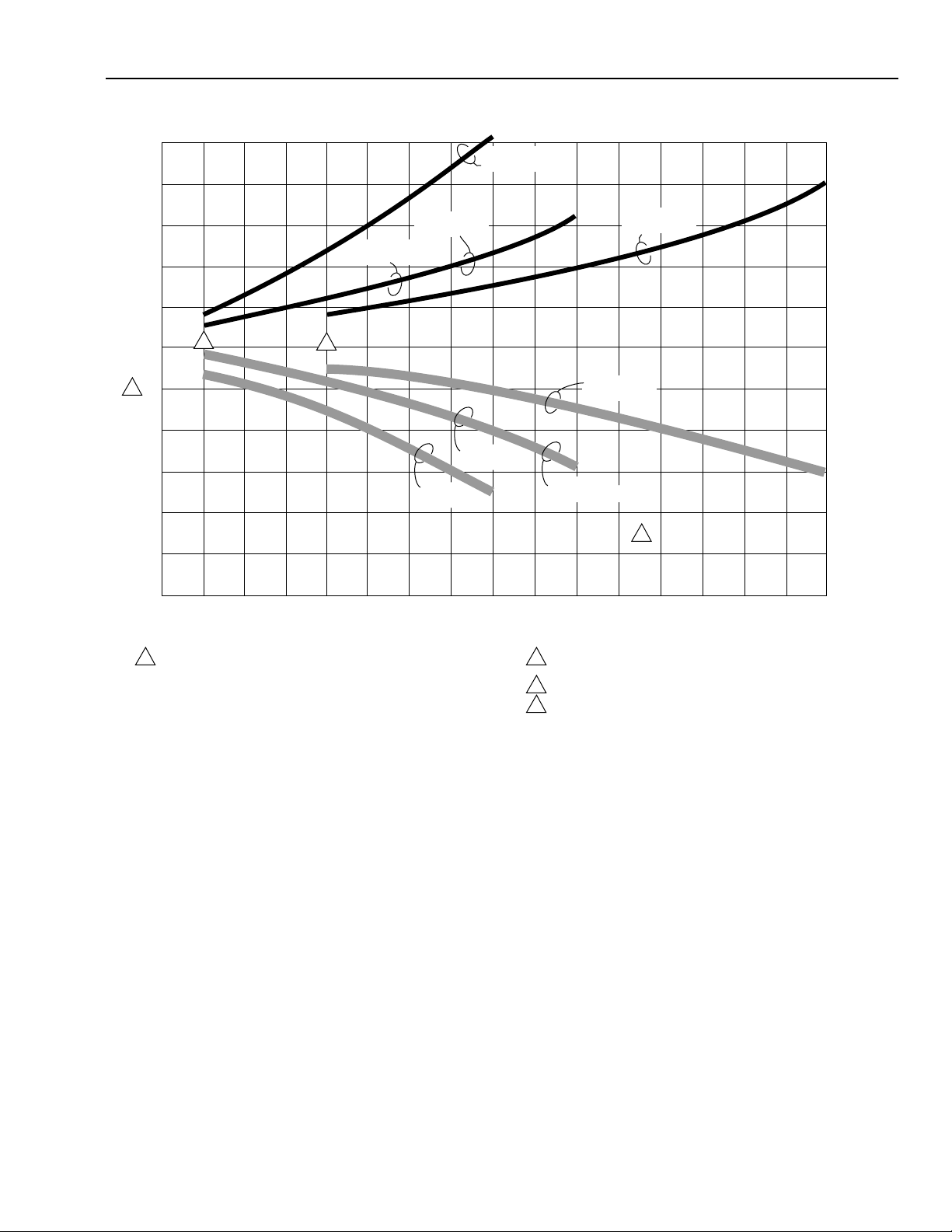
AIR CLEANER EFFICIENCY AND PRESSURE DROP AT VARIOUS AIRFLOW RATES.
16 x 20 in.
[406 x 508 mm]
16 x 25 in.
[406 x 635 mm]
20 x 20 in.
[508 x 508 mm]
F300E ELECTRONIC AIR CLEANER
.25
[62.2]
.20
[49.7]
20 x 25 in.
[508 x 635 mm]
.15
[37.3]
10
[24.9]
.05
[12.4]
PRESSURE DROP IN in. wc [Pa]
100
1
90
80
70
60
50
DUST SPOT EFFICIENCY, PERCENT
400
[680]
1 EFFICIENCY RATINGS BASED ON NATIONAL BUREAU OF
STANDARDS INITIAL DUST SPOT METHOD USING ATMOSPHERIC
DUST, AND AMERICAN SOCIETY OF HEATING, REFRIGERATING
AND AIR-CONDITIONING ENGINEERS STANDARDS 52.1-92.
2
500
[850]
600
[1020]
[1190]
700
3
800
[1360]
900
[1530]
Fig. 1. Air cleaner efficiency and pressure drop at various airflow rates.
Weight:
See T ab le 2.
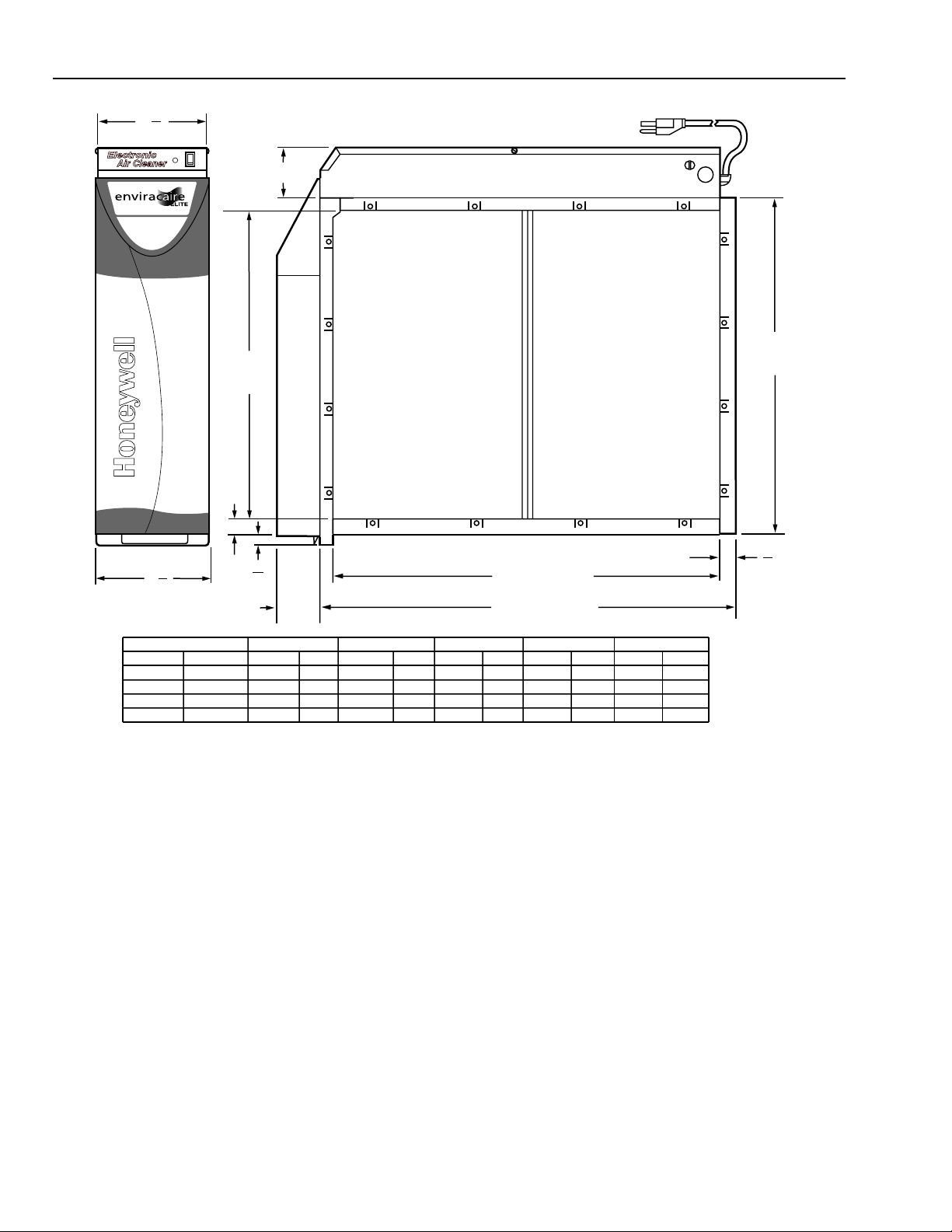
Dimensions:
See Fig. 2.
16 x 20 in.
(406 x 508 mm)
1000
[1700]
20 x 20 in.
(508 x 508 mm)
1100
1200
[1870]
[2040]
CAPACITY IN cfm [m /hr]
0
20 x 25 in.
(508 x 635 mm)
16 x 25 in.
(406 x 635 mm)
4
1400
1300
[2210]
3
2 MINIMUM RECOMMENDED cfm FOR 16 x 25 in. [406 x 635 mm],
20 x 20 in. [508 x508 mm], 16 x 20 in. [406 x508 mm] MODELS.
3 MINIMUM RECOMMENDED cfm FOR 20 x 25 in. [508 x 635 mm] MODEL.
4 SELECT SIZE THAT MOST CLOSELY FITS DIMENSIONS OF
FURNACE/AIR HANDLER RETURN AIR OPENING
[2380]
1500
[2550]
1600
[2720]
1700
[2890]
1800
[3060]
1900
[3230]
2000
[3400]
M14730
Accessories:
203365A Conversion Kit for changing 120V, 60 Hz power
supply to 240V, 60 Hz or 220/240, 50 Hz.
W8600F Air Cleaner Monitor.
W8600A AIRWATCH™ Indicator.
Underwriters Laboratories Inc. Listed:
File No. E30954.
Repair Parts:
See Replacement Parts/Exploded View section.
3
68-0240-1
Page 4
F300E ELECTRONIC AIR CLEANER
3
6
8
(162)
SYSTEM
DIM. E
(SEE TABLE)
DIM. A
(SEE
TABLE)
6
(172)
IN.
16 X 25
16 X 20
20 X 25
20 X 20
3
4
F300
MM
406 X 635
406 X 508
508 X 635
508 X 508
5
8
(16)
2-1/2
(63)
DIM. A
IN. MM IN. MM
14 7/16
14 7/16
18 7/16
18 7/16
367
367
468
468
16 3/16
16 3/16
20 3/16
20 3/16
DIM. B
411
411
513
513
Fig. 2. Installation dimensions of Electronic Air Cleaner in in. (mm).
PLANNING THE INSTALLATION
Application
The F300E Electronic Air Cleaner is used in a forced air
heating, cooling, or ventilating system. It removes airborne
particles from the air circulated through it. All models have
an internal air flow switch that operates the air cleaner when
the system blower is on.
Review Installation Requirements
The air cleaner should be installed where all the air passing
through the system circulates through it. The best location is
in the return air duct next to the blower compartment so the
air cleaner can help keep the blower motor and evaporator
coils clean.
IMPORTANT
Do not mount in the discharge air duct.
DIM. B
(SEE TABLE)
7
8
DIM. C (SEE TABLE)
DIM. D (SEE TABLE)
DIM. C
IN. MM IN. MM
23 1/4
591
18 1/4
457
23 1/4
591
18 1/4
457
DIM. D
25
20
25
20
626
509
626
509
DIM. E
IN. MM
2 3/4
2 3/4
2 3/4
2 3/4
70
70
70
70
(22)
M14731
For most efficient air cleaning, airflow must be spread evenly
across the face of the air cleaner. If the duct is a different
size than the air cleaner cabinet, gradual transitions are
recommended. If the duct turns sharply just before the air
cleaner, turning vanes are recommended.
Applications with Air Conditioning
The air cleaner should be installed upstream from the
evaporator coil. The air cleaner will help keep the coil clean,
reducing maintenance.
Applications with a Humidifier
An evaporative humidifier can be mounted upstream from
the air cleaner. An atomizing humidifier should be mounted
downstream from the air cleaner, even though hard water
salts will be blown into the living space and deposited as
dust. If an atomizing humidifier must be mounted upstream
from the air cleaner:
68-0240-1
4
Page 5

F300E ELECTRONIC AIR CLEANER
1. Mount it as far as possible upstream from the air
cleaner.
2. Install a standard disposable furnace filter between the
humidifier and the air cleaner to trap water droplets
and hard water salts.
3. Frequently clean the air cleaner to prevent a hard
water salt buildup.
NOTE: The volume of water that passes through an
atomizing humidifier can overload the air
cleaner, resulting in hard water salts being
deposited as dust in the living space.
Applications with an Activated Carbon Filter
An activated carbon (charcoal) filter can be used to remove
odors or other gaseous contaminants (not particle-based)
that are not removed by the air cleaner. Locate the carbon
filter:
• Downstream from the air cleaner. This means that dust
from the carbon filter will not be collected by the air
cleaner and will be deposited in the living space.
• Outside the air cleaner cabinet. Some carbon filters are
combustible and contact with high voltage could result in
smoke or fire.
• Where carbon granules cannot fall into the electronic cell.
If necessary, use a disposable furnace filter between the
carbon filter and the electronic cell.
• With proper transitions, if the activated carbon filter
requires a differently sized duct than the air cleaner. Allow
20 degrees expansion per side, per fitting.
NOTE: Honeywell does not offer carbon filters. Refer to
an activated carbon filter manufacturer for sizing
and application.
Applications with Outdoor Air Intake
Return air temperature must be at least 40°F (4°C). Lower
temperatures can cause ionizer wire failure. If outdoor air is
used, warm it upstream from the air cleaner by:
• Making sure the outdoor intake is far enough upstream
from the air cleaner so the return and outdoor air is
thoroughly mixed. Stratified air can dump a stream of very
cold air into one section of the air cleaner.
• Adding baffles upstream from the air cleaner to force
thorough air mixing.
• Installing a Honeywell Home Ventilation System that
transfers up to 80 percent of the heat from the exhaust air
to the incoming outside air. This keeps the incoming air
above 40°F (4°C) and reduces energy usage.
• Installing a preheater if large amounts of outdoor air are
used. The preheater, which could be an electric strip
heater or hot water coil, should be controlled by a
thermostat. Hot water or steam coils should be protected
by a freeze-up control.
Optional W8600F Air Cleaner Monitor
The terminal board is recessed slightly so it or the wires will
not interfere with installation. The entire power supply box
can be unplugged and removed to provide access to the
terminals. The W8600F Air Cleaner Monitor can be mounted
in the living area or in the furnace room. It should be located
in a convenient location to observe the display.
Optional W8600A AIRWATCH™ Indicator
The W8600A can be mounted next to the thermostat or in
any other location in the living area of the home where the
display can be conveniently observed. No wiring is
necessary.
Choose Location
Choose a location that is readily accessible for regular
inspection and cleaning. Allow at least 13 in. (330 mm) in
front of the access door for removing the prefilter and
electronic cell. Allow enough room above the power supply
so it can be serviced without removing pipes, ducts, or other
heating system components.
The air cleaner must be installed where the temperature will
not exceed 40° to 125°F (4° to 52°C).
Choose Mounting Position
WARNING
Heavy Equipment.
Can cause injury or equipment damage.
Do not mount the air cleaner with the access door
facing down. If the access door faces down, the latch
may not hold, and the cell and prefilter can fall
unexpectedly. Also, nothing holds the cell and
prefilter in place when the access door is opened.
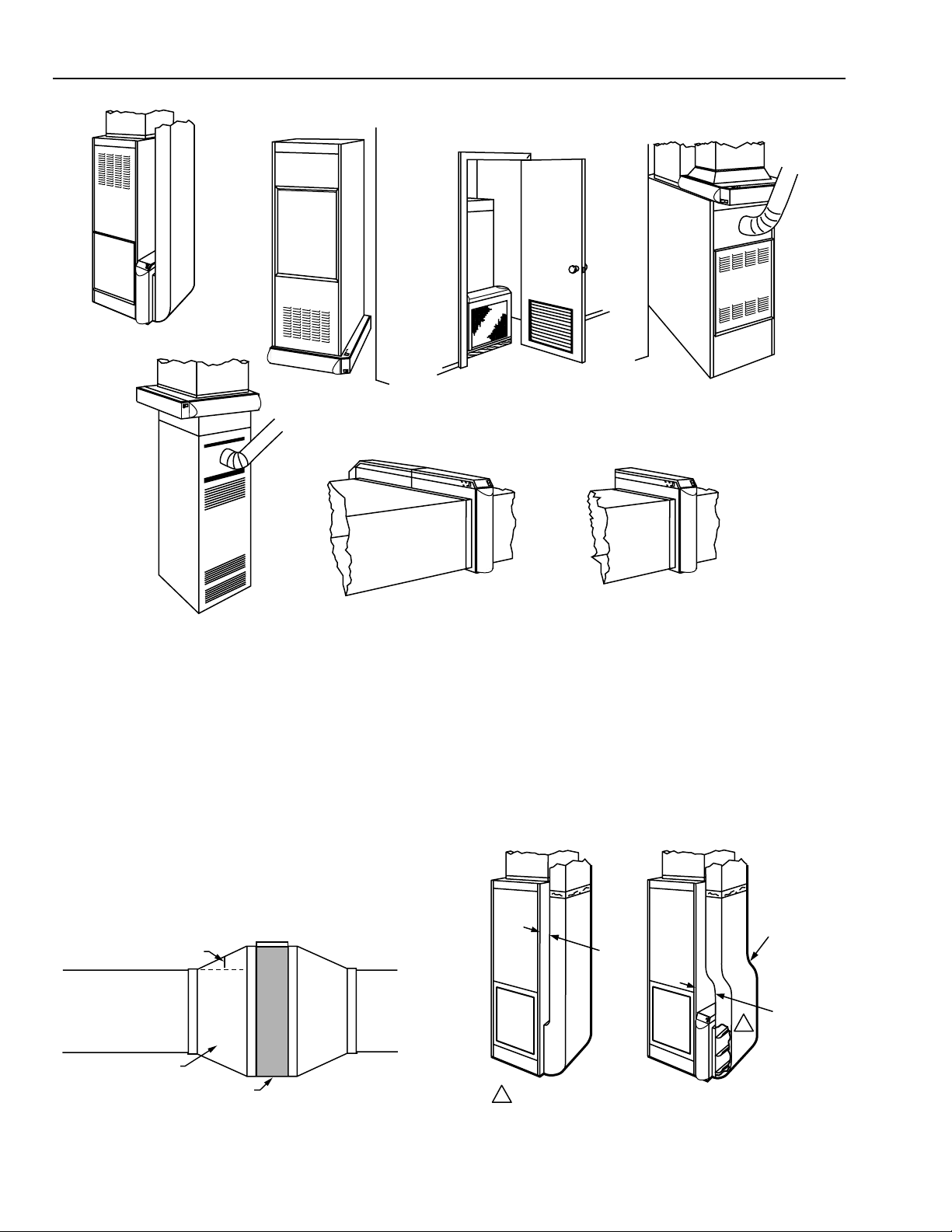
The air cleaner can be mounted in any position except with
the access door facing down. Following is a list of air cleaner
mounting positions for a variety of furnace installations.
NOTE: At least 13 in. (330 mm) clearance is required
between the access door and any obstructions
for cell and prefilter maintenance.
— Upflow “Highboy” furnace: Side installation; air cleaner is
mounted vertically where return enters side inlet of
furnace. See Fig. 3A.
— Upflow “Highboy” furnace: Installation beneath furnace
(air cleaner cabinet can easily support weight of furnace
and air conditioner coil). Air cleaner is mounted
horizontally where return enters from below. See Fig.
3B.
— Upflow “Highboy” furnace: Closet installation. Air cleaner
is mounted vertically on furnace between furnace and
louvered return air opening in closet door. See Fig. 3C.
—“Lowboy” furnace: Air cleaner is mounted horizontally in
return plenum just above furnace, opposite of supply
plenum. See Fig. 3D.
— Downflow “Counterflow” furnace: Air cleaner is mounted
horizontally in return duct or plenum just above furnace.
See Fig. 3E.
— High capacity system: Two or more air cleaners can be
used together. See Fig. 3F.
— Horizontal furnace: Air cleaner is mounted vertically
where return enters. See Fig. G.
5
68-0240-1
Page 6
F300E ELECTRONIC AIR CLEANER
A
E
B
C
D
F
Fig. 3. Mounting positions with variety of furnace installations.
Determine Duct Design Requirements
The air cleaner is adaptable to all new or existing forced air
heating, cooling and ventilating systems used in residential
applications. Transitions, turning vanes, or offsets may be
needed in some applications for effective operation.
Transitions
Transitions are needed when the duct is a different size than
the air cleaner cabinet. Gradual transitions reduce air
turbulence and increase efficiency. Limit expansion to no
more than 20 degrees or about 4 in. per running foot (100
mm per 300 linear mm) on each side of a transition fitting.
See Fig. 4.
CHANGE DUCT SIZE GRADUALLY TO MINIMIZE TURBULENCE.
20 DEGREE EXPANSION PER SIDE PER
FITTING (4 in. PER LINEAR FOOT
[100 mm PER 300 LINEAR mm]).
RETURN
AIR DUCT
G
M14732A
Turning Vanes
If the air cleaner is installed close to an elbow or angle
fitting, install turning vanes inside the angle to distribute
airflow more evenly across the face of the cell. See Fig. 5.
Offsets
If the duct connection to the furnace in a side installation
allows less than 7 in. (178 mm) for mounting the air cleaner
cabinet, add an offset to the elbow. See Fig. 5.
TYPICAL USE OF DUCT OFFSET TO ALLOW
SPACE FOR ELECTRONIC AIR CLEANER.
1
OFFSET
AT LEAST
7 in.
(178 mm)
LESS
THAN
7 in.
(178 mm)
TRANSITION FITTING
ELECTRONIC AIR CLEANER CABINET
Fig. 4. Change duct size gradually
to minimize turbulence.
68-0240-1
M5626A
1 TURNING VANES HELP DISTRIBUTE AIRFLOW EVENLY.
M14733
Fig. 5. Typical use of duct offset to allow
space for electronic air cleaner.
6
Page 7
F300E ELECTRONIC AIR CLEANER
INSTALLATION
When Installing this Product…
1. Read these instructions carefully. Failure to follow them
could damage the product or cause a hazardous
condition.
2. Check the ratings given in the instructions and on the
product to make sure the product is suitable for your
application.
3. Installer must be a trained, experienced service
technician.
4. After installation is complete, check out product
operation as provided in these instructions.
WARNING
Electric Shock Hazard.
Can cause electrical shock or equipment
damage.
Do not connect to power before installation is
complete.
Unpack Electronic Air Cleaner
❑ Check that all components are included. The electronic
air cleaner is shipped assembled. The unit consists of a
galvanized steel cabinet, power supply with on-off switch
and neon light, two electronic cells and prefilters, access
door, and product data literature.
❑ Order W8600F (optional), mounting hardware and
installation literature separately.
❑ Order W8600A (optional), including mounting hardware,
batteries, and literature separately.
❑ Place blocks under the cabinet so the unit is firmly
supported and level. The 5/8 in. (16 mm) mounting foot on
the cabinet hinge plate provides the minimum clearance
required for the access door hinge.
❑ Attach the cabinet securely to the furnace. The unit can
be attached directly, as shown, or a starting collar can
first be fitted in the furnace opening. Either drill holes and
fasten with sheet metal screws or rivets, or use slip joints.
See Fig. 6.
Clean Blower Compartment
❑ Remove and discard the existing furnace filter.
❑ Thoroughly clean the blower compartment.
❑ If possible, power vacuum the ductwork to remove
accumulated dust in an existing home, or construction dirt
in a new home. The electronic air cleaner cannot remove
dust that has settled in the blower compartment and
distribution ducts.
❑ Check the edges of the furnace fan blades for dirt buildup
and clean as necessary. The fan will not deliver the rated
cfm if the blades are dirty.
Fasten Cabinet To Furnace
NOTE: This procedure shows a side installation on a
typical highboy furnace. You may need to alter
the procedure to fit your application.
❑ Remove and set aside the access door, electronic cell(s)
and prefilter(s).
❑ Align the cabinet with the return air opening.
❑ Create opening in furnace to match air cleaner cabinet
opening.
❑ Install a transition when the furnace and air cleaner
openings are different sizes. See Fig. 4.
M14734
Fig. 6. Fasten cabinet to furnace.
Install Turning Vanes
❑ Mount turning vanes inside the elbow or angle fitting that is
directly against the air cleaner cabinet. See Fig. 5 and 7.
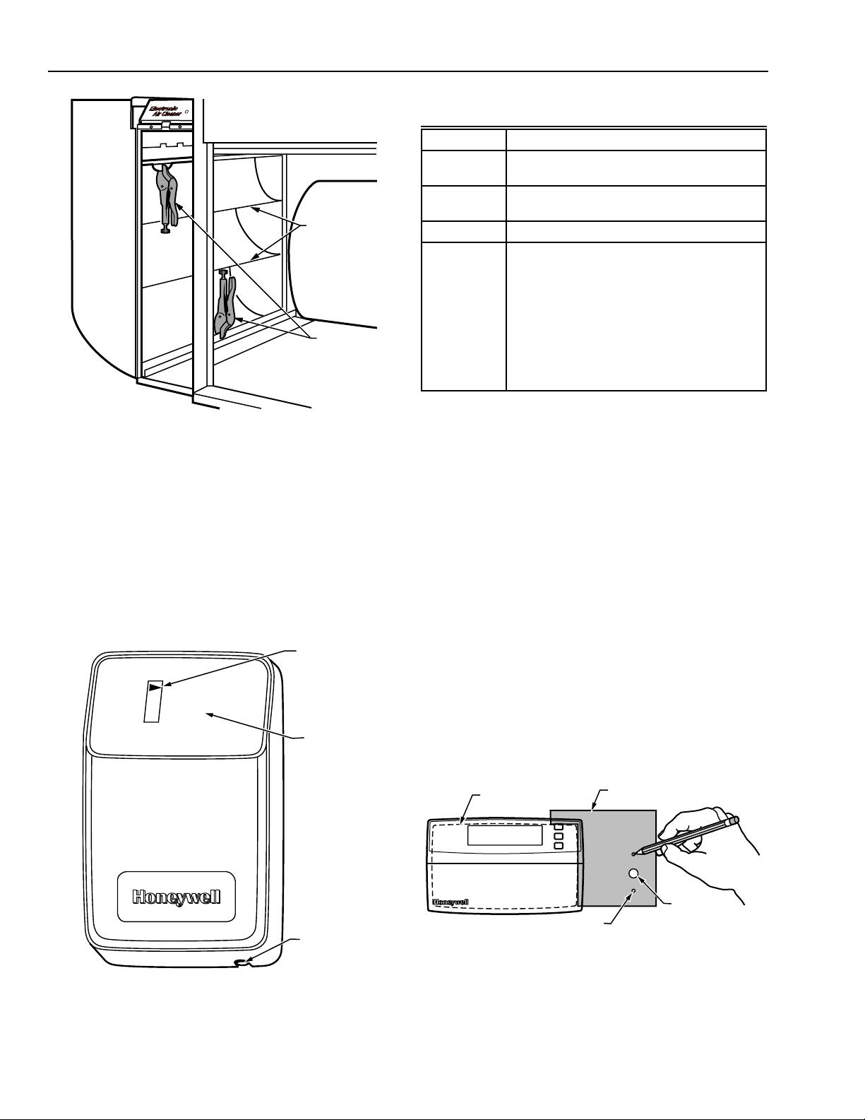
Fasten Cabinet To Ductwork
❑ Install a transition when the opening in the air cleaner
cabinet and the duct are different sizes. See Fig. 4.
❑ Fasten the other side of the cabinet to the elbow using
sheet metal screws, rivets, or slip joints as appropriate. If
drilling holes, use locking pliers to help hold the unit in
place during drilling. See Fig. 7.
7
68-0240-1
Page 8
F300E ELECTRONIC AIR CLEANER
(2)
M
E
T
S
Y
S
TURNING
VANES
LOCKING
PLIERS
M14735
Fig. 7. Connect ductwork to air cleaner. Note
turning vanes. Locking pliers hold duct to air
cleaner cabinet during installation.
Install Optional W8600F Air Cleaner Monitor
The W8600F Air Cleaner Monitor is an option available for
use with the F300E.
Table 3. Description of W8600F
Function Indicator Panel.
Indicators Condition
ON EAC is powered and system blower is
running.
BATTERY Battery that maintains W8600F memory is
low and needs to be replaced.
SERVICE EAC prefilter and cells need to be washed
FAULT • Shorting of collector plates.
• Continuous ionizer or collector plate
arcing.
• Power supply failure.
• Excessive current.
• Major reduction in high voltage.
• EAC prefilter and cells are past
SERVICE level of dirt and need to be
washed immediately.
Call a service technician.
W8600F Location
The styling of the W8600F is designed to blend with the
latest T8600 family of Honeywell Chronotherm® IV Deluxe
Programmable Thermostats. A special mounting template is
included for mounting next to the T8600. The W8600F can
also be mounted at any other convenient location in the
living area or equipment room.
NOTE: The W8600F shares no electrical connections
with the thermostat.
.
The W8600F function indicator panel has four liquid crystal
display (LCD) arrowheads that point to ON, BATTERY,
SERVICE or FAULT. See Fig. 8. The arrowheads darken to
indicate the existing EAC condition. See Table 3.
LCD
ON
BATTERY
SERVICE
FAULT
Air Cleaner Monitor
FUNCTION
INDICATOR
PANEL
RESET BUTTON
M11965
Mounting
The following mounting instructions assume that the W8600F
is mounted next to a T8600 Thermostat. If installing the
monitor at another location, modify the procedure to fit the
installation.
1. Hold the mounting template (included in the bag
assembly) next to the T8600 as shown in Fig. 9.
2. Mark the holes for the screw anchors and the
3-conductor thermostat cable.
3. Remove the template and drill the holes.
4. Remove the W8600F from the base.
5. Position the W8600F base over the holes and install
the anchors and screws. Tighten the screws until the
base is mounted firmly on the wall.
THERMOSTAT
WALLPLATE
MOUNTING HOLES
Fig. 9. Positioning mounting template.
MOUNTING
TEMPLATE
WIRING HOLE
M11971
68-0240-1
Fig. 8. W8600F Air Cleaner Monitor features.
8
Page 9

F300E ELECTRONIC AIR CLEANER
Select Wash Frequency
Use the W8600F DIP switches to program the time between
SERVICE indications. Be sure to select the setting according
to the conditions of the home. Factors to consider include the
duty cycle of the EAC, the number of people and pets, and
activities such as woodworking and other crafts that are being
done in the home.
Refer to Table 4 to select the wash frequency. Set the
W8600F DIP switches to match the selection. See Fig. 10.
The time listed represents actual run time of the EAC, not
calendar days.
Table 4. Wash Frequency Options.
DIP Switch Settings
F1 F2 F3
Off Off Off 10
Off Off On 20
Off On Off 30
Off On On 40
On Off Off 50
On Off On 70
On On Off 100
On On On 180
BACK OF W8600F
Wash Frequency
(Days)
Wiring
1. Run a 3-conductor thermostat cable (up to
18 gauge) from the W8600F to the terminal strip on
the air cleaner.
IMPORTANT
Connect cable to W8600F before attaching to the
air cleaner terminals to minimize the risk of
damage due to static electricity.
2. Connect the wires to terminals 1, 3 and 4 on the
W8600F. See Fig. 10.
3. Check that the battery is correctly installed in the
W8600F battery holder.
4. Snap the W8600F onto the base.
5. Turn off the power for the EAC.
WARNING
Electric Shock Hazard.
Can cause electrical shock or equipment
damage.
Disconnect EAC power and open the access door
before opening the power supply box cover.
6. Open the power supply box cover.
7. Remove the plug from the side of the power supply
box (plug can be a metal knockout or a blank terminal
strip).
8. Install the terminal block/cable assembly supplied with
W8600F kit.
9. Plug the connector on the end of the cable assembly
into the J2 terminal on the driver board (included with
W8600F kit). See Fig. 11.
UP
1 2 3
1
4
3
Fig. 10. Back of W8600F.
BATTERY
IN HOLDER
DIP SWITCHES
WIRING
TERMINALS (3)
RESET BUTTON
M11969A
MOUNTING
SCREW
S
Y
S
T
E
M
TERMINAL
STRIP
POWER SUPPLY
BOX COVER
J1
DRIVER
BOARD
J2
POWER
SUPPLY
POWER SUPPLY BOX
M14736
Fig. 11. Installing the driver board on the EAC.
9
68-0240-1
Page 10

F300E ELECTRONIC AIR CLEANER
10. Plug the driver board assembly into the J1 power
supply connector.
11. Replace the power supply box cover.
12. Connect the three wires from the W8600F to the EAC
terminals 1, 3 and 4. See Fig 12.
W8600F
1
1
ELECTRONIC AIR CLEANER
TERMINAL STRIP
ON POWER BOX
4
2
3
1
R
B
Y
1 CONNECT TO W8600F TERMINALS BEFORE CONNECTING TO
POWER BOX.
GREEN
G
RED
BLUE
4
3
THREE-WIRE
THERMOSTAT CABLE
M11974
Fig. 12. Wiring W8600F to F300E power box
terminal strip (two-cell model).
NOTE: Connect terminal 1 to 1, 3 to 3 and 4 to 4.
13. Turn on the EAC power.
14. Turn on the system fan.
15. Push the W8600F reset button. All four indicators on
the display will flash 5 times. The ON indicator will stay
active as long as the EAC and system fan are on. See
Fig. 13.
O
n
B
a
tte
ry
S
e
rv
ic
e
F
a
u
lt
A
ir C
le
a
n
e
r M
o
n
ito
r
The W8600A function indicator panel has four liquid crystal
display (LCD) arrow indicators that point to Battery, Air
Cleaner, UV Air Treatment, and Humidifier. See Fig. 14. The
blinking arrowheads indicate the devices that need service.
See Table 5.
Table 5. W8600A.
LCD
If arrow is flashing
or unit
is beeping...
Battery Batteries need
changing
Rset by...
Changing batteries
within 30 seconds of
removing old
batteries to maintain
correct indication
time.
Air Cleaner Media filter needs
replacing or
electronic filter
needs washing.
Pressing and holding
reset button for 10
seconds or until
arrow is no longer
displayed.
UV Air
Treatment
UV lamps need
replacing in UV air
treatment system.
Humidifier
Humidifier pad
needs replacing.
NOTE: The W8600A beeps whenever an arrow is blinking
to alert you to identify the device that needs
service. After servicing, press the reset button at
the botton of the W8600A and hold for 10 seconds
to reset the timer.
LCD
TM
Battery
Air Cleaner
UV Air Treatment
Humidifier
Honeywell.com/yourhome
FUNCTION
INDICATOR
PANEL
M15586
Fig. 13. Complete T8600/W8600F installation.
OR Install Optional W8600A-1007
AIRWATCH™ Indicator
The W8600A AIRWATCH Indicator is an option available for
use with the F300E. It is a battery-operated timer. Installation
only requires drilling holes in the wall to mount the device.
68-0240-1
RESET BUTTON
M14696
Fig. 14. W8600A AIRWATCH Indicator features.
Set DIP Switches
1. Set then DIP switches according to equipment
installed in the home:
a. Use default position set at the factory when
alldevices (air cleaner, UV air treatment system,
humidifier) are installed in the home.
b. Move DIP switch to left (off position) when adevice
is not installed in the home.
10
Page 11

PREFILTER GUIDES
CELL KEY
M5639
CELL
KEY
ALTERNATE
HOLES FOR
KEY
CELL KEY
SCREW
DOWNSTREAM
AIRFLOW
NOTE: The UV air treatment system and the humidifier
settings are for one year. Theair cleaner
settings are selectable according to
homeowner activities and needs.
2. Determine the air cleaner filter run time you desireand
set the DIP switches accordingly:
a If air cleaner filter is used, select desired filter time
of 3, 6, 9 or 12 months. Follow the settings on the
back of the W8600A to set the DIP switches for the
desired number of months.
b. If air cleaner filter is not used, move the filter time
DIP switches 4 and 5 to the left (off).
c. Use factory default settings to change the media filter
or wash the electronic filter ev ery three months.
Seal Joints
❑ Seal all joints in the return air system between the air
cleaner and the furnace to prevent dust from entering the
clean airstream. Use optional air cleaner cabinet gasket
kit (part no. 32002109-001), mastic or foil tape.
F300E ELECTRONIC AIR CLEANER
Fig. 16. Position of cell key determines orientation
of cell (arrow on key must point downstream).
4. Tighten the screw into the new hole.
5. Insert the electronic cell. The ionizer section will now
be on the air-entering (upstream) side of the cabinet.
Disable Unused Prefilter Guide
❑ Crimp the end of the downstream (closest to the furnace)
prefilter guide to prevent incorrect prefilter installation
following cleaning. See Fig. 15.
S
Y
S
T
E
M
M14737
Fig. 15. Crimping prefilter guide.
Position Cell Key
The electronic cell must always be installed so the ionizer
section is on the upstream side. A factory-installed cell key
on the bottom of the cabinet allows the cell to be inserted in
only one direction. If the arrow molded into the plastic key
points in the same direction as the airflow, the ionizer will
always be on the upstream side.
Attach Cell Handle(s)
The cell handles must be installed on the end of the cell
closest to the access door. To install:
1. Orient the cell as it will be when installed. The gray
contact board must be toward the power supply and
the airflow arrow stamped into the cell must point
downstream.
2. Hold the handle sideways and insert the solid tab on
the back of the handle into the slot in the cell. Turn the
handle 90 degrees clockwise to align the divided tab
with the square hole. See Fig. 17.
INSTALL HANDLE ON END OF CELL
CLOSEST TO ACCESS DOOR.
ROTATE 90
DEGREES
FOLD TAB
TO LOCK
HANDLE
IN PLACE
M6047A
Fig. 17. Install handle on end of
cell closest to access door.
3. Insert the divided tab into the square hole.
4. Fold up the wedge and insert it into the divided tab to
lock the handle in place. If necessary, press with a
blunt instrument like the end of a pliers.
If the position of the key must be reversed, proceed as
follows:
1. Remove the electronic cell.
2. Remove the screw holding the cell key in place.
See Fig. 16.
3. Turn the key around and place it over the opposite
holes. The tab on the bottom fits into the larger hole,
and the screw fits into the smaller hole. Make sure the
arrow on the key points in the direction of the air flow
(downstream).
Reassemble Air Cleaner
❑ Insert the electronic cell with the gray contact board
toward the power supply and the airflow arrow pointing
downstream. If the cell does not slide easily into the
cabinet, check the orientation of the cell key.
❑ Insert the prefilter on the upstream side of the cabinet in
the guide provided.
❑ Replace the access door. Insert the tab on the bottom of
the door into the slot in the cabinet, then swing it closed
and press into place. The door must be firmly in place or
the air cleaner will not operate.
11
68-0240-1
Page 12

F300E ELECTRONIC AIR CLEANER
BLACK
5
BLACK
BLACK COLLECTOR
BLACK
TEST
BUTTON
CONTACT
BOARD
RED IONIZER
P3
P4
POWER
J4
SUPPLY
RED
2
4
B4
RED
R3
Y2
GREEN
G1
1 INTERLOCK SWITCH.
2 SHORTING BAR.
3 AIRFLOW SWITCH DISABLE JUMPER.
4 OPTIONAL W8600F AIR CLEANER MONITOR. DRIVER
BOARD AND CABLE PROVIDED WITH W8600F.
5 NEON LIGHT.
6
5
2
4
BLUE
J1
J2
Fig. 18. Internal schematic for electronic air cleaner with W8600F.
Complete Wiring
WARNING
Electric Shock Hazard.
Can cause personal injury.
Do not use an extension cord.
• Assure all wiring complies with local codes and
ordinances.
• The line voltage power source must match the voltage
and frequency printed on the label inside the access
door.
• When the system fan comes on the Air Flow Switch
(AFS) senses the negative pressure in the duct and
turns the power supply on. If power to the air cleaner is
controlled by another switch,such as a sail switch or
fan timer board, the AFS can be disabled by cutting
the jumper on the back of the AFS circuit board. See
Fig. 18.
J5
J3
J1
ORANGE
GRAY
VIOLET
BLACK
W4 W2 W1 W3
AIRFLOW SWITCH BOARD
BROWN
P2
P1
BLACK
3
REMOVING COVER
FROM POWER BOX.
1
BLACK
1
BLACK
2
BLACK
WHITE
M11975
GREEN
❑ Plug the electronic air cleaner directly into the correct
voltage and frequency outlet. See Fig. 18 for internal
schematic.
NOTE: To reduce the risk of electric shock, this
product has a grounding type plug that has a
third (grounding) pin. This plug will only fit into
a grounding type power outlet. If the plug does
not fit into the outlet, contact a qualified
electrician to install the proper outlet. Do not
change the plug in any way.
68-0240-1
3
M14738A
Fig. 19. Removing cover from power box.
12
Page 13

F300E ELECTRONIC AIR CLEANER
❑ Alternatively, the electronic air cleaner can be wired with
conduit.
1. Open access door.
2. Remove and retain the (2) screws from the front of the
power box and the (2) screws from the sides of the
power box. See Fig. 19.
3. In the power box, remove and retain (2) wire nuts that
connect the line cord leads to the power box wiring.
4. Remove the power cord green lead from the green
grounding screw on the wiring compartment barrier.
5. Remove the power cord and the strain relief.
6. Install the plug (provided with the literature pack) in the
hole left by the power cord.
7. Attach conduit through a power box side knockout.
8. Wire the air cleaner directly to line voltage using wire
nuts. See Fig. 20. Secure ground connection to the
green ground screw on the wiring compartment
barrier.
9. Replace power supply cover and access door.
WIRING
COMPARTMENT
ELECTRONIC
AIR CLEANER
POWER SUPPLY. PROVIDE DISCONNECT MEANS AND
1
OVERLOAD PROTECTION AS REQUIRED.
2
THE AIR CLEANER CAN BE COMPLETELY ISOLATED FROM
THE ELECTRICAL CIRCUIT OF THE HVAC SYSTEM UNLESS
REQUIRED BY LOCAL CODE TO USE SAME CIRCUIT. ANY
CONVENIENT HOUSE CIRCUIT CAN POWER AIR CLEANER,
REGARDLESS OF ELECTRICAL RATING OF HVAC SYSTEM.
BLACK
BROWN
2
L1 (HOT)
1
L2
M5707
Fig. 20. Conduit connection for electronic air cleaner.
OPERATION
Large particles (lint, hair) are caught by the prefilter. As the
dirty air passes through the intense high voltage electric field
surrounding the ionizer wires, all particles are given an
electrical charge. The air then moves through the collector
part of the cell where alternate parallel plates are charged
positively and negatively, creating a uniform electrostatic
field. The charged particles are attracted to and collected on
the plates that have the opposite electrical charge. The air
leaving the air cleaner has fewer particles. Each time the air
circulates through the electronic air cleaner, more particles
are removed.
CHECKOUT
Inspect the Installation
Make sure:
• Turning vanes and transitions, as needed, are properly
installed.
• Sheet metal joints between air cleaner and furnace are sealed.
• All sheet metal connections are complete.
• Original furnace filter has been removed and the blower
compartment cleaned.
• If atomizing humidifier is installed upstream from the air
cleaner, a disposable furnace filter is installed between
the humidifier and the air cleaner.
• Outside air, if used, is mixed with return air or heated, as
necessary, before it can reach the air cleaner.
• Airflow arrows on the electronic cell point downstream.
• Prefilter is on the upstream side of the cell.
• Cell handle faces outward.
• Electronic cell and prefilter are clean and dry.
• W8600F (if included) wiring connections are properly
made.
Check Air Cleaner Operation
With all components in place, turn on the air cleaner switch
and energize the system blower. Check the following points
of operation:
1. The neon light next to the on-off switch is on. If a
W8600F is part of the installation, also check the wall
panel and make sure the ON indicator is lit. The
W8600F FAULT indicator will come on if there is a
problem with the high voltage power supply.
2. Turn off the system blower. The neon light should go
off after a few seconds. The neon light shows that the
air cleaner is energized and the high voltage power
supply is working properly.
3. With a multispeed blower, repeat steps 1 and 2 for
each fan speed.
4. If operation is not as described, refer to the
Troubleshooting section.
SERVICE
CAUTION
Sharp Edges.
Can cause personal injury.
Carefully handle the cell(s) or wear protective gloves
to avoid cuts from the sharp metal edges.
Cleaning the Cell(s) and Prefilter(s)
To assure optimum performance from the air cleaner, the
cell(s) and prefilter(s) must be cleaned regularly—every one
to six months. Washing frequency will vary depending on the
number of family members, pets, activities (such as cooking
or woodworking) and smoking habits. Use the wash
reminder schedule on the last page of this document to help
establish and maintain a regular cleaning schedule. Keep
your wash reminder schedule in a convenient location.
If the air cleaner has a W8600F Air Cleaner Monitor the
SERVICE indicator will activate to indicate that it is time to
wash the prefilter(s) and cell(s). The time between activation
of the SERVICE indicator is based on air cleaner run time
that is selected by the installer at installation. See W8600F
installation instructions, page 8, for instructions on selecting
air cleaner run time. Pressing the Reset button on the
bottom right corner of the housing resets the W8600F
SERVICE indicator. See Fig. 8.
If the air cleaner has a W8600A AIRWATCH Indicator, the Air
Cleaner LCD arrow will blink to indicate it is time to wash the
prefilter(s) and cell(s). The time between activation of the Air
Cleaner LCD is based on air cleaner run time that is
selected at installation. See Set DIP Switches section in the
W8600A installation instructions for information on selecting
air cleaner run time. After servicing the filters, press and hold
the reset button for 10 seconds or until the LCD arrow is no
longer displayed to reset the W8600A AIRWATCH Indicator.
13
68-0240-1
Page 14

F300E ELECTRONIC AIR CLEANER
NOTE: To let the heating or air conditioning system
operate normally while the cell(s) are being
washed, simply turn off the air cleaner switch.
Vacuum the prefilter or brush, or soak it in a tub. Do not
wash the prefilter in the dishwasher or car wash.
Automatic Dishwasher
CA UTION
Burn Hazard.
Can cause personal injury.
Allow the cell(s) to cool completely in the dishwasher
at the end of the wash cycle or wear protective
gloves to avoid burns. Hot water can accumulate in
the tubes supporting the collector plates. Tip the
cell(s) so these tubes will drain.
Record wash times on the chart on last page.
IMPORTANT
• Check the dishwasher owner’s manual. Some
manufacturers do not recommend washing
electronic cell(s) in their dishwashers.
• If the dishwasher has upper and lower arms,
position the cell(s) carefully to allow good water
circulation.
• Be careful to avoid damaging the cell(s) when
placing them in the dishwasher. Broken ionizer
wires or bent collector plates are not included in the
warranty.
• Very dirty cell(s), especially from tobacco or
cooking smoke, can discolor the plastic parts and
the lining of some dishwashers. This discoloration is
not harmful. To minimize it, wash the cell(s) more
frequently or try a different brand of detergent.
• Do not allow the dishwasher to run through the
dry cycle. This will bake on any contaminants not
removed during the wash cycle and reduce air
cleaner efficiency.
Washing the Cell(s) in a Container
CA UTION
Hazardous Chemical.
Can cause personal injury.
• Do not splash the detergent solution in eyes. Wear
rubber gloves to avoid prolonged detergent
contact with skin.
• Keep detergent and solution out of reach of
children.
NOTE: Always wash the cell(s) first, then the
1. Use a large enough container, such as a laundry tub
or trash container, to hold one or both cell(s).
NOTE: Sharp corners on the cell(s) can scratch the
2. Dissolve about 3/4 cup of automatic dishwasher
detergent per cell in enough hot water to cover the
cell(s). If the detergent does not dissolve readily, or
forms a scum on the water, try another brand, or use
softened water.
3. After the detergent has completely dissolved, place
the cell(s) in the container and let soak for 15 to 20
minutes. Agitate up and down a few times, and
remove. See Fig. 21.
4. Next, wash the prefilter(s) the same way. Empty and
rinse the wash container.
prefilter(s), to keep heavy prefilter lint from
getting caught in the cell(s).
surface of a bathtub.
WEAR GLOVES
TO PROTECT
HANDS FROM
DETERGENT
SOLUTION.
1. Put the cell(s) on the lower rack of the dishwasher with
the airflow arrow pointing up. It may be necessary to
remove the upper rack. Do not block water flow to the
upper arm.
HINT: Lay a few large water glasses between the
2. Using regular dishwashing detergent, allow the
dishwasher to run through the complete wash and
rinse cycle. Do
let the cell(s) cool completely before removing, or wear
protective gloves when removing the cell(s).
Remember that water may be trapped inside the
cell(s). Tip the cell(s) so the tubes can drain.
3. Wipe the ionizer wires and contact board on the end of
the cell using thumb and forefinger with a small, damp
cloth.
4. Inspect the dishwasher. Rerun the wash and/or rinse
cycle with the dishwasher empty if there is dirt or
residue from washing the cell(s). If dirt or residue
seems excessive, wash the cell(s) more often or try a
different detergent.
68-0240-1
spikes on the lower rack and rest the cell(s)
on them so the spikes do not damage the
aluminum collector blades.
not
use the dry cycle. To avoid burns,
M922A
Fig. 21. Washing cell(s) in container.
14
Page 15

F300E ELECTRONIC AIR CLEANER
5. Rinse the cell(s) and prefilter(s) with a hard spray of
very hot water; rinse the tub clean, then fill the tub with
clean hot water and soak for 5 to 15 minutes. Rinse
until the water draining from the cell(s) and prefilter(s)
no longer feels slippery.
6. Soak cell(s) and prefilter(s) in a final clear water rinse
for ten minutes.
7. Wipe the ionizer wires and contact board on the end of
the cell using your thumb and forefinger with a small,
damp cloth.
Reinstall the Cell(s) and Prefilter(s)
1. Inspect the cell(s) for broken ionizer wires and bent
collector plates. Repair as necessary or take to a
Honeywell Authorized Air Cleaner Repair Station.
2. Slide the prefilter(s) into the upstream prefilter guides.
3. Slide in the air cleaner cell(s) so the airflow arrow
points downstream and the handle(s) faces outward.
4. Firmly close the access door.
5. Turn on the air cleaner. If the cell(s) and prefilter(s) are
wet, the neon light may not come on and you may hear
arcing. If the arcing is annoying, simply turn off the air
cleaner for two to three hours or until the cell(s) is dry.
If the air cleaner has an Air Cleaner Monitor, the FAULT
indicator may activate when the cell(s) and prefilter(s) are
wet. Again, if the FAULT indicator is annoying, simply turn off
the air cleaner for two to three hours or until the cell(s) and
prefilter(s) are dry.
COLLECTOR
TERMINAL
IONIZER
TERMINAL
COLLECTOR
TERMINAL
M6155
Fig. 22. Use ohmmeter to check electronic
cells for short circuits.
REPLACING AN IONIZER WIRE.
Replacing Ionizer Wires
Broken or bent ionizer wires can cause an electrical short to
ground, often resulting in visible arcing or sparking. Do not
use cell(s) until broken wires are removed. Cells can be used
temporarily with one wire missing, but replace the wire as
soon as possible.
Replacement wires are supplied cut to length with eyelets on
both ends for easy installation. See Parts and Accessories
not illustrated on Page 18 for Part No. To install:
1. Hook the eyelet on one end of the wire over the spring
connector on one end of the cell. See Fig. 23. Be
careful to avoid damaging the spring connector or
other parts of the cell.
2. Hold the opposite eyelet with a needle nose pliers and
stretch the wire the length of the cell. Depress the
opposite spring connector and hook the eyelet over it.
3. Check the cell for short circuits using an ohmmeter.
Check the resistance between the frame of the cell
and both the ionizer and the collector contacts. In each
case, the resistance should be infinite. See Fig. 24.
PRESS
DOWN
IONIZER
WIRE
SPRING
CONNECTORS
EYELETS
1
IONIZER
WIRE
15
NEEDLENOSE
PLIERS
TWO EYELETS HOLD IONIZER WIRE TO CELL.
1
Fig. 23. Replacing an ionizer wire.
M1540B
68-0240-1
Page 16

F300E ELECTRONIC AIR CLEANER
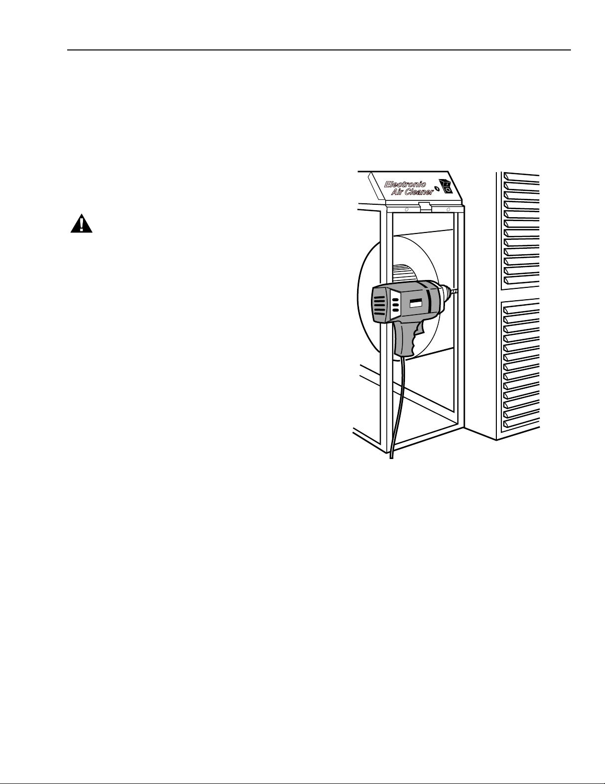
Modification to Reduce Ozone Odor
WARNING
Electric Shock Hazard.
Can cause personal injury.
Always disconnect power and open the access door
before opening the power supply cover.
The electronic air cleaner generates a small amount of
ozone in normal operation. During the first week or two of
operation, the amount may be higher because of sharp
edges on some of the new high voltage metal parts. Normal
use quickly dulls these edges.
The average person can detect the odor of ozone in
concentrations as low as 0.003 to 0.010 parts per million
(ppm). The electronic air cleaner contributes 0.005 to 0.010
ppm of ozone to the indoor air. The U.S. Food and Drug
Administration and Health and Welfare Canada recommend
that indoor ozone concentration should not exceed
0.050 ppm. As a comparison, the outdoor ozone level in
major cities is sometimes as high 0.100 ppm.
However, if desired, the ozone generated by the air cleaner
can be reduced in one of two ways:
1. Install an activated carbon filter downstream from the
air cleaner. Make sure particles from the air filter
cannot fall into the air cleaner.
WARNING
Electric Shock Hazard.
Can cause personal injury.
Only a trained service technician should perform the
following procedure.
2. This will reduce ozone production about 20 to 25
percent and reduce efficiency about seven to ten
percent, depending on actual airflow delivered by the
furnace blower.
a. Unplug or disconnect power supply to the air
cleaner.
b. Open the access door.
c. Remove the power box cover. See Fig. 25.
d. Locate J5 shorting bar on the power supply. See
Fig. 26. Remove the shorting bar and reinstall on
only one pin.
NOTE: The ozone will be reduced, but the shorting
bar is available for reinstallation if needed.
e. Replace the power supply cover and access the
door. Turn on the power.
f. Repeat the checkout procedure before leaving
the job.
REMOVE POWER BOX FROM AIR CLEANER AND REMOVE THE COVER.
2
1
Fig. 24. Remove power box from air cleaner and remove cover.
3
4
M14739A
68-0240-1
16
Page 17

F300E ELECTRONIC AIR CLEANER
P3
J5 SHUNT
IN OZONE
REDUCTION
POSITION
J5 IN
NORMAL
POSITION
P4
E5
E6
J4
J5
E4 E3
E2
E1
J3
J1
P2
P1
M15099
Fig. 25. Move J5 shorting bar to reduce ozone production about 20 to 25 percent.
17
68-0240-1
Page 18

F300E ELECTRONIC AIR CLEANER
REPLACEMENT PARTS/EXPLODED VIEW
Nominal Return Air Opening
No. Description
(406 x 508 mm)
1 Access Door 32004876-004 32004876-004 32004876-003 32004876-003
2 Electronic Cell FC37A1114 (2) FC37A1130 (2) FC37A1049 (2) FC37A1064 (2)
3 Cell Handle 137266 (2) 137266 (2) 137266 (1) 137266 (2)
4 Prefilter 209989 (2) 203371 (2) 203373(2) 203372 (2)
5 Cell Key 136518 (1) 136518 (1) 136518 (1) 136518 (1)
16 x 20 in.
6 Power Box Assembly
208418E (1) 208417B (1) 208418A (1) 208417A (1)
Includes No. 8-20,
120V, 60 Hz
240V, 60 Hz N/A N/A N/A N/A
a
7 Switch 203321 (1) 203321 (1) 203321 (1) 203321 (1)
8 Power Box Cover
32004930-002 32004930-001 32004930-002 32004930-001
and Label
9 Power Supply,
208414G (1) 208414B (1) 208414B (1) 208414A (1)
120V, 60 Hz
240V, 60 Hz N/A N/A N/A N/A
10 Interlock Bracket and
a
4074ETG (1) 4074ETG (1) 4074ETG (1) 4074ETG (1)
Switch
11 W8600 Terminal Strip Supplied with W8600F
12 Terminal Board
203329B (1) 203329B (1) 203329C (1) 203329B (1)
Assembly Front
13 Terminal Board
203329A (1) 203329A (1) 203329A (1) 203329A (1)
Assembly Rear
14 Barrier Plate 203331 (1) 203331 (1) 203331 (1) 203331 (1)
15 Strain Relief 203852 (1) 203852 (1) 203852 (1) 203852 (1)
16 Line Cord 4074ETD (1) 4074ETD (1) 4074ETD (1) 4074ETD (1)
17 Hole Plug 203847 (1) 203847 (1) 203847 (1) 203847 (1)
18 Neon Assembly 4074EYS (1) 4074EYS (1) 4074EYS(1) 4074EYS (1)
19 Airflow Switch 4074ETH (1) 4074ETH (1) 4074ETH (1) 4074ETH (1)
20 FC37A Bag Assembly
4074EHG 4074EHG 4074EHG 4074EHG
for cell repair.
Contains
2 Connector Clips,
1 Terminal Board and
Instructions.
(#) = Quantity required per unit N/A = Not available as merchandized part.
a
Use 203365A Conversion Kit for changing 120V, 60 Hz power supply to 240V, 60 Hz or 220V/240V, 50 Hz.
16 x 25 in.
(406 x 635 mm)
20 x 20 in.
(508 x 508 mm)
20 x 25 in.
(508 x 635 mm)
68-0240-1
18
Page 19

F300E ELECTRONIC AIR CLEANER
19
12
11
18
8
6
10
7
14
9
13
16
15
17
20
5
4
3
2
1
Fig. 27. Components of the Electronic Air Cleaner (2-cell model shown).
M14740
19
68-0240-1
Page 20

F300E ELECTRONIC AIR CLEANER
Parts and Accessories Not Illustrated
Nominal Return Air Opening
16 x 20 in.
Description
Air Cleaner Cabinet Gasket Kit 32002109-001 32002109-001 32002109-001 32002109-001
Ionizer Wires (multiples of 5) 136434BA 136434BA 136434AA 136434AA
Mounting Screws 136375 (6) 136375 (6) 136375 (6) 136375 (6)
Air Cleaner Monitor
(beige color)
Premier White®
AIRWATCH® Indicator
Premier White® Air Cleaner Monitor W8600F1014 W8600F1014 W8600F1014 W8600F1014
2-Stage EAC Cell with
Collector Clip
240V Conversion Kit 203365A 203365A 203365A 203365A
(#) = Quantity required per unit N/A = Not available as merchandized part.
(406 x 508 mm)
W8600F1008 W8600F1008 W8600F1008 W8600F1008
W8600A1007 W8600A1007 W8600A1007 W8600A1007
N/A FC37A1247 (2) N/A FC37A1239 (2)
16 x 25 in.
(406 x 635 mm)
20 x 20 in.
(508 x 508 mm)
20 x 25 in.
(508 x 635 mm)
ELECTRICAL TROUBLESHOOTING
WARNING
Electric Shock Hazard.
Can cause personal injury or equipment damage.
The following procedures expose hazardous live
parts. Disconnect from power between checks and
proceed carefully. These instructions are for use by
qualified personnel only.
Tools and Equipment
Troubleshooting the electronic air cleaner requires:
• Needle nose pliers for stringing ionizer wires and
inserting edge connectors.
• Test meter.
Neon Light (On Power Box)
The neon light is powered through the power supply and is
on when the power supply output voltage is normal.
FAULT Indicator (Air Cleaners with W8600F)
The FAULT indicator is on the W8600F. It activates to
indicate the following conditions: excessive dirt loading,
partial shor ting of the collector, continuous ionizer or
collector arcing, power supply failure, excessive ionizer
current, or any condition causing a major reduction in high
voltage.
Power Box
WARNING
Electric Shock Hazard.
Can cause personal injury.
Always turn off power and remove access door
before removing power supply or its cover.
The solid state power supply within the power supply box
can be replaced. When troubleshooting indicates a power
supply problem, replace the entire power box or replace the
power supply within the box. See Installation Instructions.
See Fig. 24 for power box removal.
Troubleshooting Procedure
The electronic air cleaner Troubleshooting charts show how
to quickly isolate a problem in the air cleaner. Although a
meter is needed for some steps, the primary diagnostic tool
is the neon light. See Fig. 28.
68-0240-1
20
Page 21

F300E ELECTRONIC AIR CLEANER
TROUBLE SHOOTING AIR CLEANERS WITH PERFORMANCE INDICATOR.
START
MAKE SURE ELECTRONIC
CELLS ARE CLEAN, DRY,
AND CORRECTLY INSTALLED.
MAKE SURE PREFILTERS ARE
IN CABINET SLOT FARTHEST
FROM FURNACE OR
AIR HANDLER.
TURN ON ELECTRONIC AIR
CLEANER AND SYSTEM FAN.
CHECK INDICATOR LIGHT
ON POWER SUPPLY.
ON
CHECK ON INDICATOR
ON W8600F.
OFF
AIR CLEANER
AND W8600F
ARE OK.
CHECK WIRING BETWEEN
W8600F AND AIR CLEANER.
USE MAX NO. 18
THERMOSTAT CABLE
CONNECTED 1(G) TO 1(G),
3(R) TO 3(R), AND 4(B) TO 4(B).
WIRING
NOT OK
FIX WIRING
ON
WIRING
OK
OFF
TO USE THIS CHART:
1. FOLLOW THE STEPS IN ORDER; DO NOT SKIP AROUND.
2. EACH TIME A PROBLEM IS FIXED, GO BACK TO START.
3. REPEAT ALL STEPS UNTIL THE AIR CLEANER CHECKS OUT OK.
WARNING
Can cause electric shock and personal injury.
Only qualified installers should use these instructions.
the service listed in these instructions and only when trained.
TURN OFF AIR CLEANER AND
REMOVE THE CELLS,
LEAVING PREFILTERS IN
PLACE. CLOSE ACCESS
DOOR AND TURN ON
AIR CLEANER.
CHECK INDICATOR LIGHT
ON POWER SUPPLY.
INSPECT CELLS FOR:
• BENT COLLECTOR PLATES.
• BROKEN IONIZER WIRES.
• DIRT ON INSULATORS.
• DAMAGED CONTACT TABS.
REPAIR OR
REPLACE CELL
Electric Shock Hazard.
Qualified installers should provide only
OFF
ON
YES NO
WARNING
HIGH VOLTAGE HAZARD.
CAN CAUSE SEVERE
PERSONAL INJURY OR DEATH.
ONLY A QUALIFIED SERVICE
TECHNICIAN SHOULD
ATTEMPT THIS STEP.
REMOVE POWER BOX COVER.
CHECK FOR CORRECT INPUT
VOLTAGE ACROSS P1 AND P2
TERMINALS ON POWER
SUPPLY.
NO
FIX WIRING
YES
CHECK W8600 BATTERY
LESS
THAN 3V
REPLACE
BATTERY
CHECK W8600 ACCORDING TO
THE INSTRUCTIONS PACKED.
FAILDED
CHECKOUT
REPLACE W8600F
WITH AN OHMMETER,
CHECK FOR SHORT CIRCUIT
3V OR
MORE
OK
BETWEEN:
• CELL FRAME AND
IONIZER SECTION.
• CELL FRAME AND
COLLECTOR SECTION.
CELL
SHORT
REPLACE
CELL
CELL IS
OK
1
INFINITE
RESISTANCE
FOR POWER SUPPLY REPLACEMENT, SEE FORM 69-1136.
Fig. 28. Troubleshooting air cleaners.
SHORT THE AIRFOLW
SWITCH DISABLE JUMPER
TO GROUND.
CHECK INDICATOR LIGHT
ON POWER SUPPLY.
ON
REPLACE
AIRFLOW
SWITCH
REPLACE
POWER
SUPPLY
OFF
1
M14741
21
68-0240-1
Page 22

F300E ELECTRONIC AIR CLEANER
68-0240-1
22
Page 23

YEAR
F300E ELECTRONIC AIR CLEANER
ELECTRONIC AIR CLEANER WASH REMINDER SCHEDULE
INSTALLATION DATE:
,
JFMAMJJASOND
M982A
23
68-0240-1
Page 24

ZAP
TRAP
IMPROVE YOUR INDOOR AIR WITH A COMPLETE
Whole House Air Quality System by Honeywell
ULTRAVIOLET AIR TREATMENT SYSTEM
• ZAP airborne germs.
• Kill most germs before they recycle
through your home.
• Prevent mold spores from growing on your
system cooling coils.
F300E ELECTRONIC AIR CLEANER
• TRAP airborne particles.
• Up to 99% efficient at capturing
airborne particles.
• Effectively REDUCES fungi, bacteria,
mold antigen, cat antigen and ragweed
pollen antigen that pass through system.
ENVIRACAIRE ELITE HUMIDIFIERS
• Moisturize parched air.
• Help maintain proper humidity to minimize
adverse health effects.
• Features special antimicrobial agent to prevent
surface growth and migration of bacteria, mold,
fungus and algae on the humidifier pad.
Honeywell offers one of the broadest families of home solutions in the
industry - ranging from thermostats, zoning, ventilation, air cleaning,
humidification to internet-enabled home control and wireless
WebPAD™ devices for web surfing and more!! Check out our offerings on-line at
... only fr om Honeywell.
Home and Building Control
Honeywell
1985 Douglas Drive North
Golden Valley, MN 55422
Home and Building Control
Honeywell Limited-Honeywell Limitée
35 Dynamic Drive
Scarborough, Ontario
M1V 4Z9
M14757
68-0240-1 G.H. Rev. 9-00
Printed in U.S.A. on recycled
paper containing at least 10%
post-consumer paper fibers.
www.honeywell.com
 Loading...