

Honeywell F300a2025 Owner's Manual
F300 Electronic Air Cleaner
PRODUCT DATA
APPLICATION
The F300 Electronic Air Cleaner is mounted in the return air
duct of a forced air heating, cooling, or ventilating system. It
captures a significant amount of the airborne particles 0.3
micron and larger from air circulated through it.
FEATURES
• Media postfilters (optional) provide enhanced filtration.
• Available in five sizes to fit most ducts; adapts to
airflow from either side.
3
• Capacity varies from 1000 cfm (2040 m
(3400 m
• Solid state power supply is self-regulating and
maintains peak efficiency during a wide range of cell
dirt loading conditions.
• Low pressure drop.
• Optional W8600F Air Cleaner Monitor indicates air
cleaner performance, reminds homeowner when filter
and cell maintenance are due and when to check the
system.
• Optional wireless W8600A AIRWATCH™ LCD indicator
provides reminder when air cleaner electronic cells
need washing, when media postfilters need replacing,
when UV lamps need replacing and when humidifier
pad needs replacing.
3
/hr), depending on size.
/hr) to 2000 cfm
Contents
Application/Features.......................................................... 1
Specifications/Ordering Information .................................. 2
Installation ........................................................................ 8
Operation .......................................................................... 11
Checkout .......................................................................... 11
Service ............................................................................. 12
Replacement Parts/Exploded View ................................... 17
68-0240EF—06

F300 ELECTRONIC AIR CLEANER
SPECIFICATIONS
IMPORTANT
The specifications given in this publication do not
include normal manufacturing tolerances. Therefore,
this unit may not exactly match the listed specifications. This product is tested and calibrated under
closely controlled conditions, and some minor differences in performance can be expected if those conditions are changed.
Model:
F300E Electronic Air Cleaner: Includes cabinet, access door,
solid state power supply, two electronic cells, two metal
mesh prefilters, and two media postfilters.
F300A,B Electronic Air Cleaner: Includes cabinet, access
door, solid state power supply, two electronic cells and two
metal mesh prefilters.
Electrical Ratings:
Voltage and Frequency: Models available for 120V, 60 Hz.,
240V, 60Hz. 120V models can be converted in the field to
240V, 60 Hz or 220/240V, 50 Hz with the 203365A
Conversion Kit.
Power Consumption:
One cell models: 22 W maximum
Two cell models: 36 W maximum.
Current Draw: See Table 1.
Ionizer Voltage: 8150 Vdc.
Collector Voltage: 4075 Vdc.
Table 1. Current Draw.
Size
in. mm 120V 220/240V
16 x 25 406 x 635 2 0.4 0.2
20 x 25 508 x 635 2 0.4 0.2
16 x 20 406 x 508 2 0.4 0.2
20 x 20 508 x 508 2 0.4 0.2
20 x
12-1/2 508 x 318 1 0.4 0.2
No.
Cells
Max Current (A)
Fractional Efficiency:
Efficiency ratings are based on American Society of Heating,
Refrigerating and Air-Conditioning Engineers Standard
52.2-1999. Efficiency ranges are defined for small particles,
E
=.3 to 1.0 micron; medium particles, E2 = 1.0 to 3.0
1
microns; and large particles, E
Table 2. Fractional Efficiency With and Without Postfilter.
With postfilter Without postfilter
= 3.0 to 10.0 microns.
3
E
= Up to 81% at 492 fpm. E1 = Up to 73% at 492 fpm.
1
E
= Up to 93% at 492 fpm. E2 = Up to 88% at 492 fpm.
2
E
= Up to 99% at 492 fpm. E3 = Up to 95% at 492 fpm.
3
ORDERING INFORMATION
When purchasing replacement and modernization products from your TRADELINE® wholesaler or distributor, refer to the
TRADELINE® Catalog or price sheets for complete ordering number.
If you have additional questions, need further information, or would like to comment on our products or services, please write or
phone:
1. Your local Honeywell Automation and Control Products Sales Office (check white pages of your phone directory).
2. Honeywell Customer Care
1885 Douglas Drive North
Minneapolis, Minnesota 55422-4386
In Canada—Honeywell Limited/Honeywell Limitée, 35 Dynamic Drive, Scarborough, Ontario M1V 4Z9.
International Sales and Service Offices in all principal cities of the world. Manufacturing in Australia, Canada, Finland, France,
Germany, Japan, Mexico, Netherlands, Spain, Taiwan, United Kingdom, U.S.A.
68-0240EF—06 2
F300 ELECTRONIC AIR CLEANER
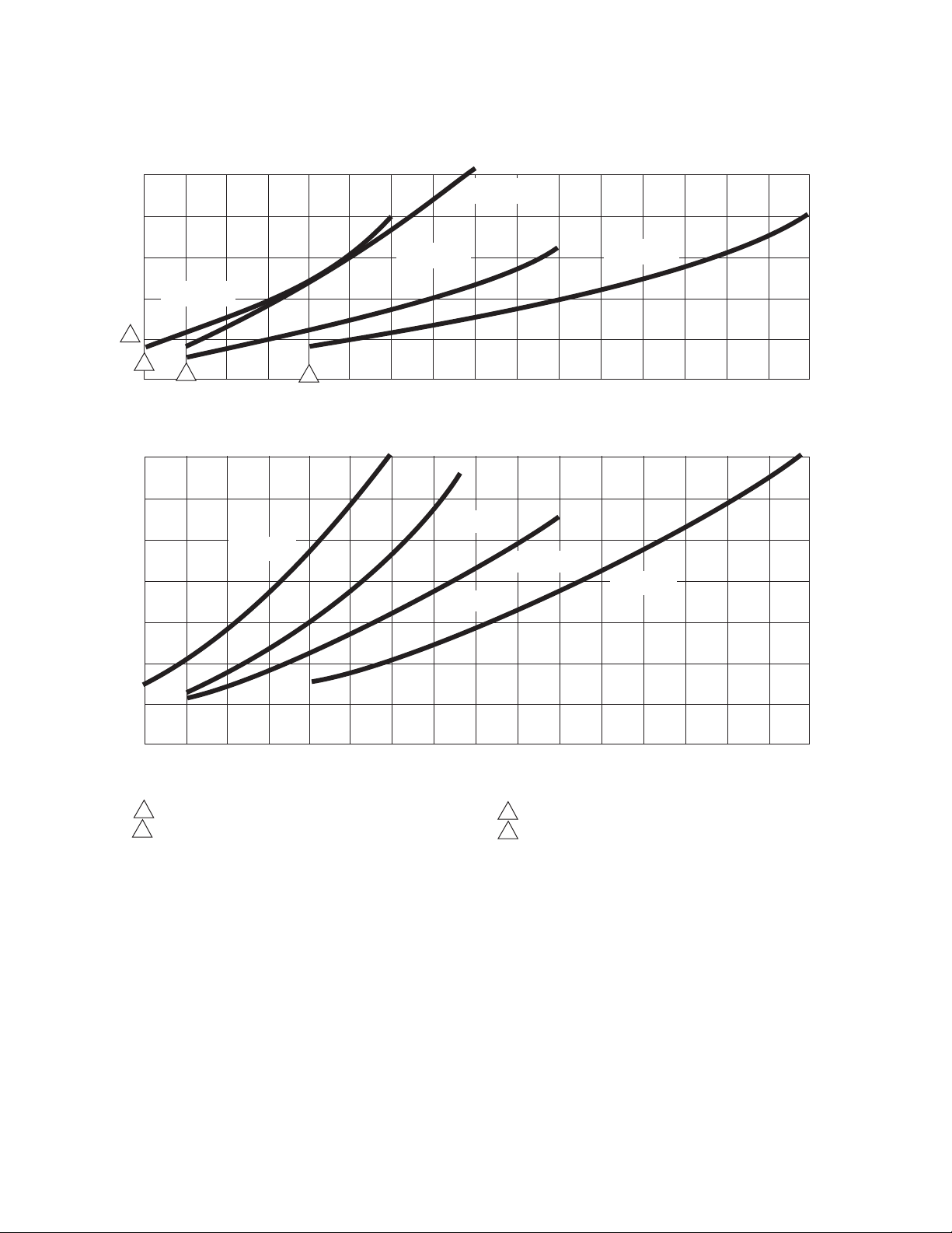
AIR CLEANER EFFICIENCY AND PRESSURE DROP AT VARIOUS AIRFLOW RATES.
WITHOUT POST FILTERS
20 x 12-1/2 in.
(508 x 318 mm)
4
1
2
400
500
(850)
600
(1020)
(680)
WITH POST FILTERS
700
(1190)
20 x 12-1/2 in.
(508 x 318 mm)
3
800
(1360)
20 x 20 in.
(508 x 508 mm)
900
(1530)
16 x 25 in.
(406 x 635 mm)
1000
(1700)
110 0
(1870)
16 x 20 in.
(406 x 508 mm)
16 x 25 in.
(406 x 635 mm)
16 x 20 in.
(406 x 508 mm)
1200
1300
(2040)
(2210)
CAPACITY IN cfm (m
20 x 20 in.
(508 x 508 mm)
1400
(2380)
3
/hr)
20 x 25 in.
(508 x 635 mm)
1500
(2550)
20 x 25 in.
(508 x 635 mm)
1600
(2720)
1700
(2890)
1800
(3060)
1900
(3230)
2000
(3400)
.25
(62.2)
.20
(49.7)
.15
(37.3)
.10
(24.9)
.05
(12.4)
0
.35
(87.2)
.30
(74.7)
.25
(62.2)
.20
(49.7)
.15
(37.3)
PRESSURE DROP IN in. wc (Pa)
400
500
(680)
(850)
1 MINIMUM RECOMMENDED cfm FOR 20 x 12-1/2 in. (508 x 318 mm) MODEL.
2 MINIMUM RECOMMENDED cfm FOR 16 x 25 in. (406 x 635 mm),
20 x 20 in. (508 x 508 mm), 16 x 20 in. (406 x 508 mm) MODELS.
600
(1020)
700
(1190)
800
(1360)
900
(1530)
1000
(1700)
110 0
1200
(1870)
(2040)
CAPACITY IN cfm (m3 /hr)
Fig. 1. Pressure Drop Vs. Airflow.
Temperature Ratings:
Operating Ambient: 40° to 125°F (4° to 52°C).
Temperature of Airflow Through Cells: 40° to 125°F
(4° to 52°C).
Maximum Cell Washing Temperature: 220°F (140°C).
Storage and Shipping Ambient: Minus 40°F to plus 140°F
(minus 40°C to plus 60°C).
Mounting:
Mounts in the return air duct of a forced air heating, cooling, or
ventilating system. Mount upstream from an atomizing
humidifier. See Planning the Installation section.
1400
1300
(2210)
3 MINIMUM RECOMMENDED cfm FOR 20 x 25 in. (508 x 635 mm) MODEL.
4 SELECT SIZE THAT MOST CLOSELY FITS DIMENSIONS OF
FURNACE/AIR HANDLER RETURN AIR OPENING
(2380)
1500
(2550)
1600
(2720)
1700
(2890)
1800
(3060)
1900
(3230)
2000
(3400)
M13654
Weight:
See Table 3.
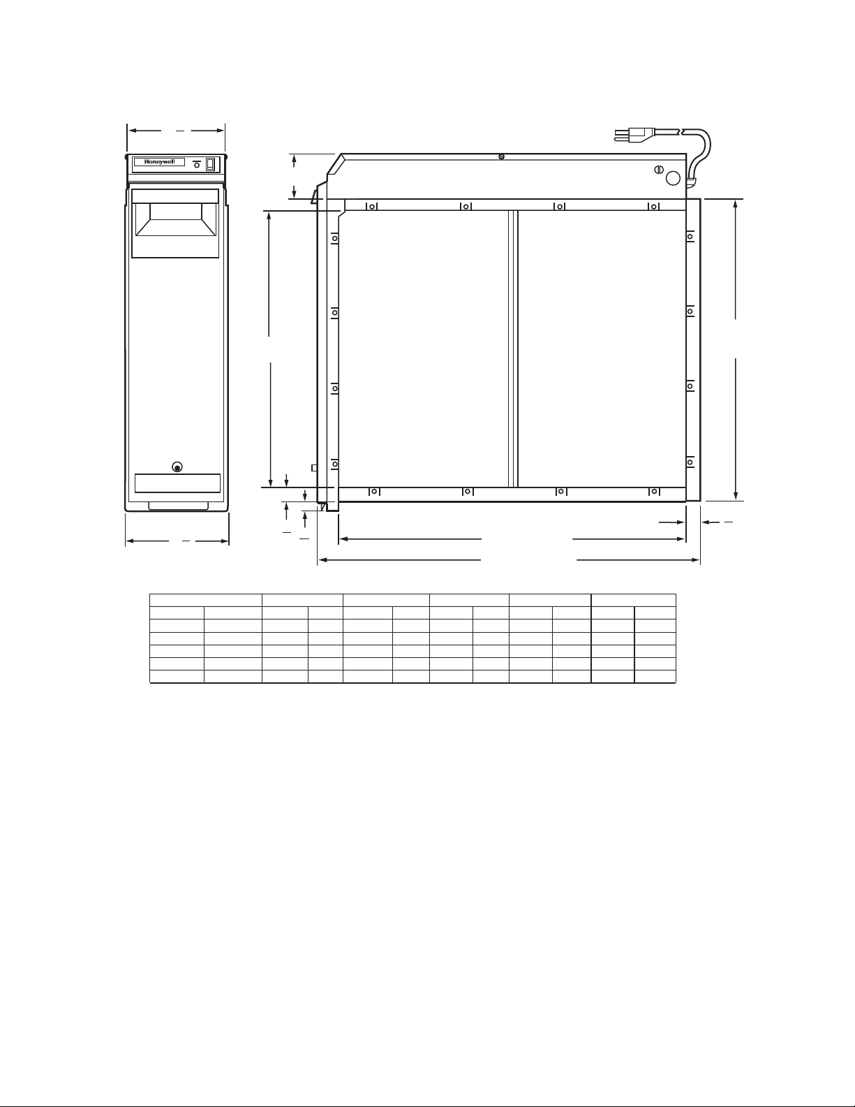
Dimensions:
See Fig. 2.
Approvals:
Underwriters Laboratories Inc. Listed: File E30954.
.10
(24.9)
.05
(12.4)
0
PRESSURE DROP IN in. wc (Pa)
3 68-0240EF—06

F300 ELECTRONIC AIR CLEANER
Accessories:
203365A Conversion Kit for changing 120V, 60 Hz power
supply to 240V, 60 Hz or 220/240V, 50 Hz.
W8600F Air Cleaner Monitor.
W8600A AIRWATCH™ Indicator.
Table 3. Shipping and Installed Weight.
16 x 20 in.
(406 x 508 mm)
Item
Electronic Cell
(each)
Shipping Weight 30 13.6 33 15.0 25 11.3 33 15.0 38 17.2
Installed Weight
(Cells included)
lb kg lb kg lb kg lb kg lb kg
5 2.25 6 2.7 7-1/2 3.4 6-3/16 2.8 7-1/2 3.4
26 11.6 28 12.7 21 9.5 29 13.2 33 15.0
16 x 25 in.
(406 x 635 mm)
Repair Parts:
See Replacement Parts/Exploded View section.
Weight
20 x 12-1/2 in.
(508 x 318 mm)
20x 20 in.
(508x 508 mm)
(508 x 635 mm)
20 x 25 in.
68-0240EF—06 4
F300 ELECTRONIC AIR CLEANER
3
6
8
(162)
ELECTRONIC AIR CLEANER
6
(172)
DIM. E
(SEE TABLE)
DIM. A
(SEE TABLE)
7
3
4
(22)
5
8
8
(16)
DIM. C (SEE TABLE)
DIM. D (SEE TABLE)
DIM. B
(SEE TABLE)
7
8
(22)
F50F SIZE
IN.
16 X 25
16 X 20
20 X 25
20 X 20
20 X 12 1/2
MM
406 X 635
406 X 508
508 X 635
508 X 508
508 X 318
DIM. A
IN. MM IN. MM
14 7/16
14 7/16
18 7/16
18 7/16
18 7/16
367
367
468
468
468
16 3/16
16 3/16
20 3/16
20 3/16
20 3/16
DIM. B
411
411
513
513
513
Fig. 2. Electronic air cleaner installation dimensions in in. (mm).
PLANNING THE INSTALLATION
Application
The F300 Electronic Air Cleaner is used in a forced air heating,
cooling, or ventilating system. It removes airborne particles
from the air circulated through it. All models have an internal air
flow switch that automatically energizes the air cleaner cells
when the system blower is on.
Review Installation Requirements
The air cleaner should be installed where all the air passing
through the system circulates through it. The best location is in
the return air duct next to the blower compartment so the air
cleaner can help keep the blower motor and evaporator coils
clean.
DIM. C
IN. MM IN. MM
23 1/4
591
18 1/4
457
23 1/4
591
18 1/4
457
10 7/8
276
DIM. D
25 1/2
20 1/2
25 1/2
20 1/2
13 1/8
648
521
648
521
333
DIM. E
IN. MM
2 3/4
2 3/4
2 3/4
2 3/4
3 5/8
70
70
70
70
92
M2872A
IMPORTANT
Do not mount in the discharge air duct.
For most efficient air cleaning, airflow must be spread evenly
across the face of the air cleaner. If the duct is a different size
than the air cleaner cabinet, gradual transitions are
recommended. If the duct turns sharply just before the air
cleaner, turning vanes are recommended.
Applications with Air Conditioning
The air cleaner should be installed upstream from the
evaporator coil. The air cleaner will help keep the coil clean,
reducing maintenance.
5 68-0240EF—06
F300 ELECTRONIC AIR CLEANER
WARNING
Applications with a Humidifier
An evaporative humidifier can be mounted upstream from the
air cleaner. An atomizing humidifier should be mounted
downstream from the air cleaner, even though hard water salts
will be blown into the living space and deposited as dust. If an
atomizing humidifier must be mounted upstream from the air
cleaner:
1. Mount it as far as possible upstream from the air cleaner.
2. Install a standard disposable furnace filter between the
humidifier and the air cleaner to trap water droplets and
hard water salts.
3. Frequently clean the air cleaner to prevent a hard water
salt buildup.
NOTE: The volume of water that is discharged from an atom-
izing humidifier can overload the air cleaner, resulting
in hard water salts being deposited as dust in the living space.
Applications with Outdoor Air Intake
Return air temperature must be at least 40°F (4°C). Lower
temperatures can cause ionizer wire failure. If outdoor air is
used, warm it upstream from the air cleaner by:
• Making sure the outdoor intake is far enough upstream from
the air cleaner so the return and outdoor air is thoroughly
mixed. Stratified air can dump a stream of very cold air into
one section of the air cleaner.
• Adding baffles upstream from the air cleaner to force
thorough air mixing.
• Installing a Honeywell Perfect Window™ Fresh Air
Ventilation System that transfers up to 80 percent of the
heat from the exhaust air to the incoming outside air. This
keeps the incoming air above 40°F (4°C) and reduces
energy usage.
• Installing a preheater if large amounts of outdoor air are
used. The preheater, which could be an electric strip heater
or hot water coil, should be controlled by a thermostat. Hot
water or steam coils should be protected by a freeze-up
control.
Optional W8600F Air Cleaner Monitor
The W8600F Air Cleaner Monitor can be mounted in the living
area or in the furnace room. It should be located in a
convenient location to observe the display.
The W8600F Air Cleaner Monitor is furnished with all the
connectors needed for easy installation. Follow the installation
instructions provided with the W8600F.
Optional W8600A AIRWATCH™ Indicator
The W8600A can be mounted next to the thermostat or in any
other location in the living area of the home where the display
can be conveniently observed. No wiring is necessary.
Choose Location
Choose a location that is readily accessible for regular
inspection and cleaning. Allow at least 13 in. (330 mm) in front
of the access door for removing the metal mesh prefilter, media
postfilter and electronic cell. Allow enough room above the
power supply so it can be serviced without removing pipes,
ducts, or other heating system components.
The air cleaner must be installed where the temperature is
between 40° to 125°F (4° to 52°C).
IMPORTANT
UV light can damage media postfilters. Avoid
installing UV lamp downstream of F300 in location
where UV light illuminates postfilter.
Choose Mounting Position
Heavy Equipment Hazard.
Can cause injury or equipment damage.
Do not mount air cleaner with access door facing down
because the latch may not hold and the cell, postfilter
and prefilter can fall unexpectedly.
NOTE: Nothing holds the cell, postfilter, and prefilter in place
when the access door is opened.
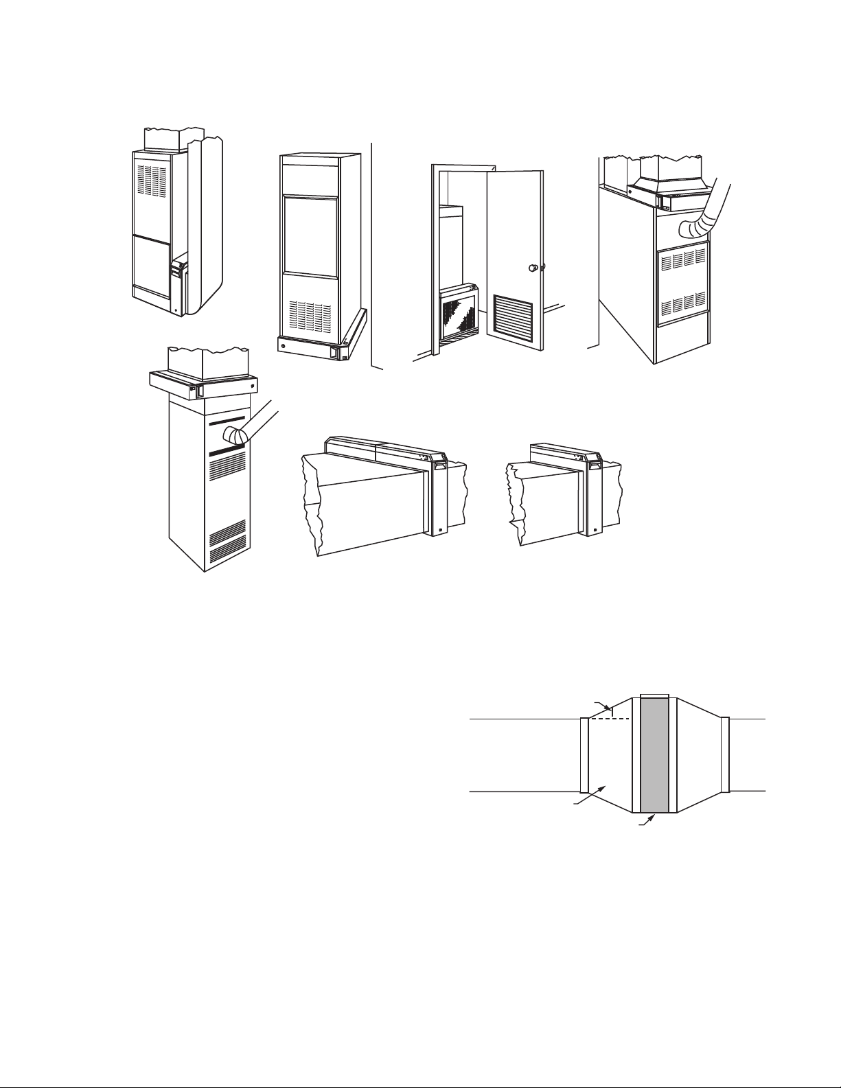
The air cleaner can be mounted in any position except with the
access door facing down. A list of air cleaner mounting
positions for a variety of furnace installations follows.
NOTE: At least 13 in. (330 mm) clearance is required
between the access door and any obstructions for
cell, postfilter and prefilter maintenance.
— Upflow Highboy furnace: Side installation; air cleaner is
mounted vertically where return enters side inlet of furnace.
See Fig. 3A.
— Upflow Highboy furnace: Installation beneath furnace (air
cleaner cabinet can easily support weight of furnace and air
conditioner coil). Air cleaner is mounted horizontally where
return enters from below. See Fig. 3B.
— Upflow Highboy furnace: Closet installation. Air cleaner is
mounted vertically on furnace between furnace and
louvered return air opening in closet door. See Fig. 3C.
— Lowboy furnace: Air cleaner is mounted horizontally in
return plenum just above furnace, opposite of supply
plenum. See Fig. 3D.
— Downflow Counterflow furnace: Air cleaner is mounted
horizontally in return duct or plenum just above furnace.
See Fig. 3E.
— High capacity system: Two or more air cleaners can be
used together. See Fig. 3F.
— Horizontal furnace: Air cleaner is mounted vertically where
return enters. See Fig. 3G.
68-0240EF—06 6
F300 ELECTRONIC AIR CLEANER
A
B
C
E
D
F
Fig. 3. Mounting positions with variety of furnace installations.
Determine Duct Design Requirements
The air cleaner is adaptable to all new or existing forced air
heating, cooling and ventilating systems used in residential
applications. Transitions, turning vanes, or offsets may be
needed in some applications for effective operation.
Transitions
Transitions are needed when the duct is a different size than
the air cleaner cabinet. Gradual transitions reduce air
turbulence and increase efficiency. Limit expansion to no more
than 20 degrees or about 4 in. per running foot (100 mm per
300 linear mm) on each side of a transition fitting.
See Fig. 4.
G
M19777
CHANGE DUCT SIZE GRADUALLY TO MINIMIZE TURBULENCE.
20 DEGREE EXPANSION PER SIDE PER
FITTING (4 in. PER LINEAR FOOT
[100 mm PER 300 LINEAR mm]).
RETURN
AIR DUCT
TRANSITION FITTING
ELECTRONIC AIR CLEANER CABINET
M5626A
Fig. 4. Change duct size gradually to minimize turbulence.
Turning Vanes
If the air cleaner is installed close to an elbow or angle fitting,
install turning vanes inside the angle to distribute airflow more
evenly across the face of the cell. See Fig. 5.
7 68-0240EF—06
F300 ELECTRONIC AIR CLEANER
WARNING
M5627A
LESS
THAN
7 in.
[178 mm]
OFFSET
AT LEAST
7 in.
[178 mm]
1
1 TURNING VANES HELP DISTRIBUTE AIRFLOW EVENLY.
E
L
E
CT
R
O
NI
C
AI
R
C
LE
A
N
E
R
TYPICAL USE OF DUCT OFFSET TO ALLOW
SPACE FOR ELECTRONIC AIR CLEANER.
M20804
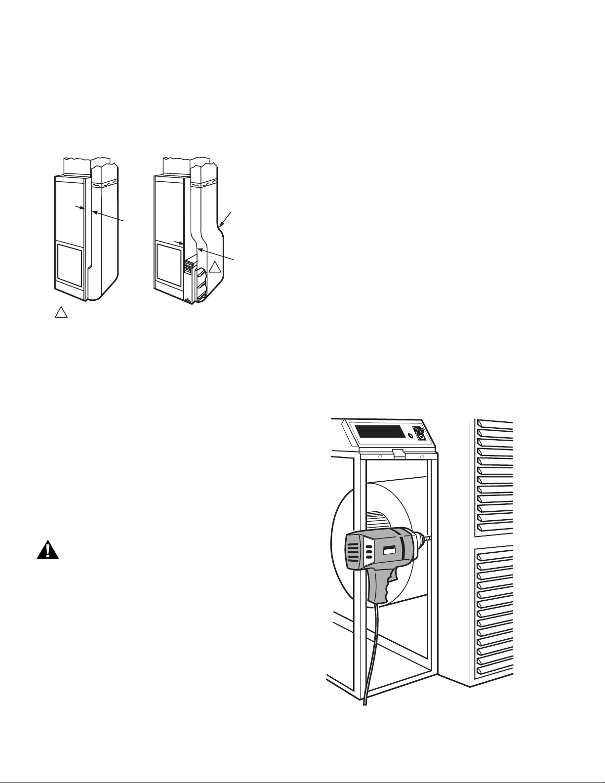
Offsets
If the duct connection to the furnace in a side installation allows
less than 7 in. (178 mm) for mounting the air cleaner cabinet,
add an offset to the elbow. See Fig. 5.
Fig. 5. Typical use of duct offset to allow space for
electronic air cleaner.
INSTALLATION
Clean Blower Compartment
Remove and discard the existing furnace filter.
Thoroughly clean the blower compartment.
If possible, power vacuum the ductwork to remove
accumulated dust in an existing home, or construction dirt in
a new home. The electronic air cleaner cannot remove dust
that has settled in the blower compartment and distribution
ducts.
Check the edges of the furnace fan blades for dirt buildup
and clean as necessary. The fan will not deliver the rated
cfm if the blades are dirty.
Fasten Cabinet To Furnace
NOTE: This procedure shows a side installation on a typical
highboy furnace. You may need to alter the procedure
to fit your application.
Remove and set aside the access door, electronic cells
metal mesh prefilters and media postfilters.
Align the cabinet with the return air opening.
Create opening in furnace to match air cleaner cabinet
opening.
Install a transition when the furnace and air cleaner
openings are different sizes. See Fig. 4.
Place blocks under the cabinet so the unit is firmly
supported and level. The 5/8 in. (16 mm) mounting foot on
the cabinet hinge plate provides the minimum clearance
required for the access door hinge.
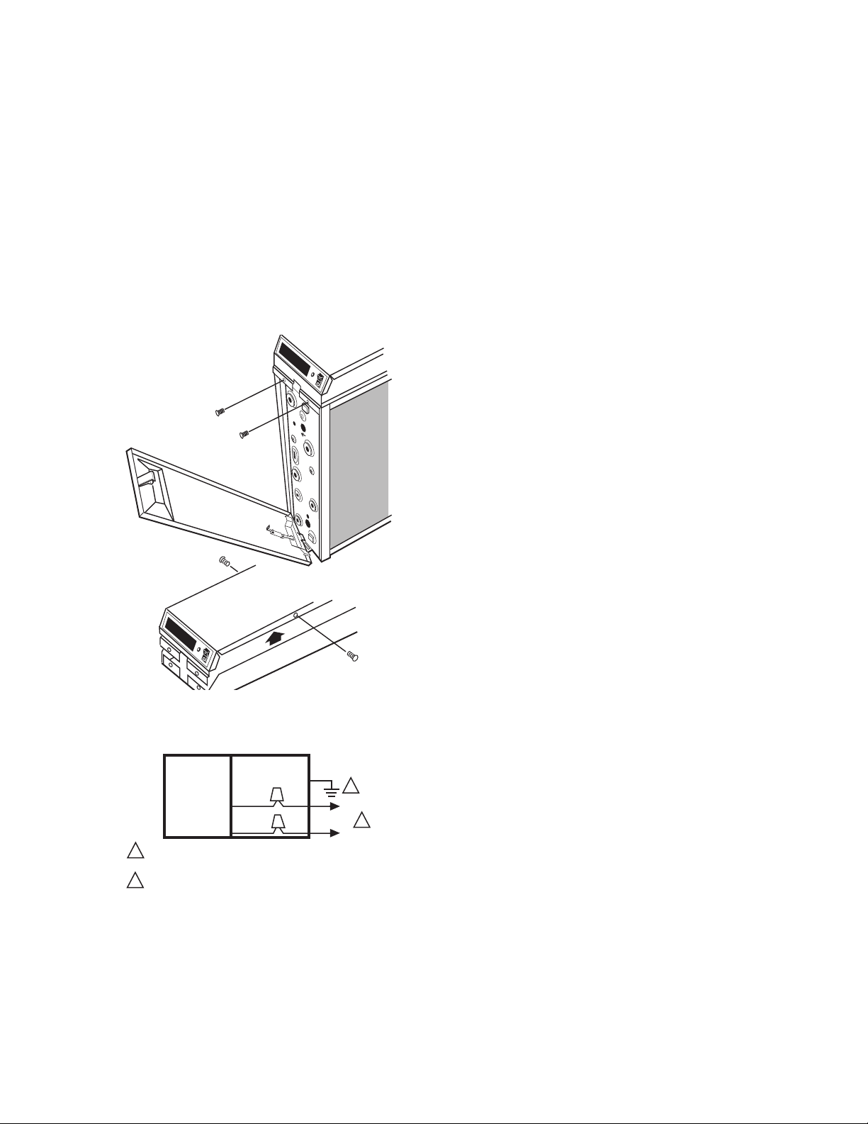
Attach the cabinet securely to the furnace. The unit can be
attached directly, as shown, or a starting collar can first be
fitted in the furnace opening. Either drill holes and fasten with
sheet metal screws or rivets, or use slip joints. See Fig. 6.
When Installing this Product...
1. Read these instructions carefully. Failure to follow them
could damage the product or cause a hazardous
condition.
2. Check the ratings given in the instructions and on the
product to make sure the product is suitable for your
application.
3. Installer must be a trained, experienced service
technician.
4. After installation is complete, check out product
operation as provided in these instructions.
Electric Shock Hazard.
Can cause electrical shock or equipment damage.
Do not connect to power before installation is complete.
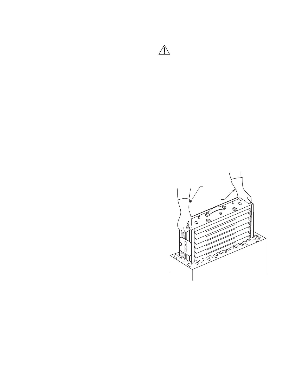
Unpack Electronic Air Cleaner
Check that all components are included. The electronic air
cleaner is shipped assembled. The unit consists of a
galvanized steel cabinet, power supply with On-Off switch
and neon light, two electronic cells, two metal mesh
prefilters, two media postfilters (on select models), access
door and product data literature.
Order W8600F (optional) including mounting hardware and
Order W8600A (optional) including mounting hardware,
installation literature separately.
batteries, and literature separately.
Fig. 6. Fasten cabinet to furnace.
68-0240EF—06 8
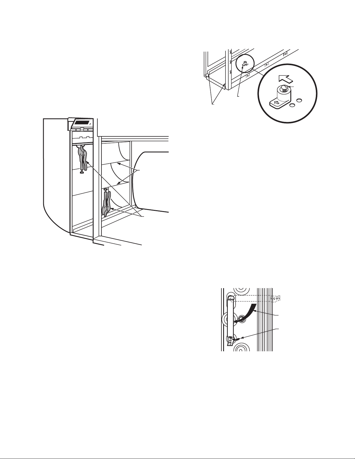
Install Turning Vanes
M20815
LOCKING
PLIERS
TURNING
VAN ES
Mount turning vanes inside the elbow or angle fitting that is
directly against the air cleaner cabinet. See Fig. 7.
F300 ELECTRONIC AIR CLEANER
Fasten Cabinet To Ductwork
Install a transition when the opening in the air cleaner
cabinet and the duct are different sizes. See Fig. 4.
Fasten the other side of the cabinet to the elbow using
sheet metal screws, rivets, or slip joints as appropriate. If
drilling holes, use locking pliers to help hold the unit in place
during drilling. See Fig. 7.
Fig. 7. Connect ductwork to air cleaner. (Note turning
vanes. Locking pliers hold duct to air cleaner cabinet
during installation.)
CELL KEY
PREFILTER GUIDES
M5639
DOWNSTREAM
CELL
KEY
AIRFLOW
CELL KEY
SCREW
ALTERNATE
HOLES FOR
KEY
Fig. 8. Position of cell key determines orientation of cell
(arrow on key must point downstream).
3. Turn the key around and place it over the opposite holes.
The tab on the bottom fits into the larger hole, and the
screw fits into the smaller hole. Make sure the arrow on
the key points in the direction of the air flow (downstream).
4. Tighten the screw into the new hole.
5. Insert the electronic cell. The ionizer section will now be
on the air-entering (upstream) side of the cabinet.
Attach Cell Handles
Cell handles included with the air cleaner must be installed on
the end of the cell closest to the access door. To install:
1. Orient the cell as it will be when installed. The gray
contact board must be up and the airflow arrow stamped
into the cell must point downstream.
2. Hold the handle sideways and insert the solid tab on the
back of the handle into the slot in the cell. Turn the
handle 90 degrees clockwise to align the divided tab with
the square hole. See Fig. 9.
Seal Joints
Seal all joints in the return air system between the air
cleaner and the furnace to prevent dust from entering the
clean airstream. Use optional air cleaner cabinet gasket kit
(part no. 32002109-001), mastic or foil tape.
Position Cell Key
The electronic cell must always be installed so the ionizer
section is on the upstream side. A factory-installed cell key on
the bottom of the cabinet allows the cell to be inserted in only
one direction. If the arrow molded into the plastic key points in
the same direction as the airflow, the ionizer is always on the
upstream side.
If position of the key must be reversed, proceed as follows:
1. Remove the electronic cell.
2.
Remove the screw holding the cell key in place. See Fig. 8.
9 68-0240EF—06
INSTALL HANDLE ON END OF CELL
CLOSEST TO ACCESS DOOR
ROTATE 90
DEGREES
FOLD TAB
TO LOCK
HANDLE
IN PLACE
M6047A
Fig. 9. Install the handle on the end of the cell closest to
the access door.
3. Insert the divided tab into the square hole.
4. Fold up the wedge and insert it into the divided tab to
lock the handle in place. If necessary, press with a blunt
instrument like the end of a pliers.
F300 ELECTRONIC AIR CLEANER
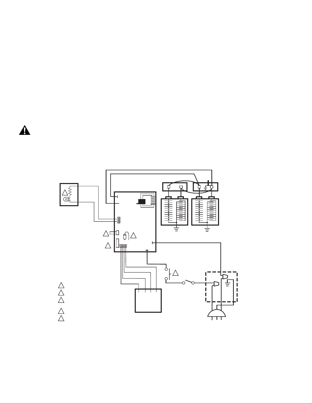
WARNING
P3
P4
P1
P2
J3
BLACK
W4 W2 W1 W3
AIRFLOW SWITCH BOARD
ORANGE
GRAY
VIOLET
BLACK
1 INTERLOCK SWITCH.
2 SHORTING BAR FOR OZONE REDUCTION.
3 AIRFLOW SWITCH DISABLE JUMPER, J8.
AIRFLOW SWITCH PLUG, J3.
4 NEON LIGHT.
5 OPTIONAL W8600F AIR CLEANER MONITOR.
M23413
POWER
SUPPLY
2
4
BLACK
BLACK
BLACK
BROWN
BLACK
BLACK
WHITE
GREEN
1
3
J4
J5
J1
BLACK
RED
TEST
BUTTON
CONTACT
BOARD
RED IONIZER
BLACK COLLECTOR
5
J8
Reassemble Air Cleaner
Insert the electronic cells with the gray contact board toward
the power supply and the airflow arrow pointing
downstream. If the cell does not slide easily into the cabinet,
check the orientation of the cell key.
Insert the metal mesh prefilters on the upstream side of the
cabinet in the guide provided.
Insert the media postfilters (on select models) on the
downstream side of the cabinet in the guide provided.
Replace the access door. Insert the tab on the bottom of the
door into the slot in the cabinet, then swing it closed and
press into place. The door must be firmly in place or the air
cleaner will not operate.
Complete Wiring
Electric Shock Hazard.
Can cause personal injury.
Do not use an extension cord.
• Assure all wiring complies with local codes and ordinances.
• The line voltage power source must match the voltage and
frequency printed on the label inside the access door.
• When the System fan comes on, the Air Flow Switch (AFS)
senses the negative pressure in the duct and turns on the
power supply. If power to the air cleaner is controlled by
another switch, the AFS can be disabled by disconnecting
the AFS plug J3 and cutting the J8 jumper on the power
supply. See Fig. 10.
Plug the electronic air cleaner directly into the correct
voltage and frequency outlet. See Fig. 10 for internal
schematic. The air cleaner operates correctly with any fan
when wired with conduit or plugged in.
NOTE: To reduce the risk of electric shock, this product has a
grounding type plug that has a third (grounding) pin.
This plug only fits into a grounding type power outlet.
If the plug does not fit into the outlet, contact a qualified electrician to install the proper outlet. Do not
change the plug in any way.
Alternatively, the electronic air cleaner can be wired with
conduit.
68-0240EF—06 10
Fig. 10. Internal schematic for electronic air cleaner.
F300 ELECTRONIC AIR CLEANER
3
1
2
REMOVING COVER
FROM POWER BOX.
ELECTRONIC
AIR CLEANER
WIRING
COMPARTMENT
BLACK
BROWN
POWER SUPPLY. PROVIDE DISCONNECT MEANS AND
OVERLOAD PROTECTION AS REQUIRED.
THE AIR CLEANER CAN BE COMPLETELY ISOLATED FROM
THE ELECTRICAL CIRCUIT OF THE HVAC SYSTEM UNLESS
REQUIRED BY LOCAL CODE TO USE SAME CIRCUIT. ANY
CONVENIENT HOUSE CIRCUIT CAN POWER AIR CLEANER,
REGARDLESS OF ELECTRICAL RATING OF HVAC SYSTEM.
M5707
2
1
2
L1 (HOT)
L2
1
1. Open access door.
2. Remove and retain the two screws from the front of the
power box and the two screws from the sides of the
power box. See Fig. 11.
3. In the power box, remove and retain two wire nuts that
connect the line cord leads to the power box wiring.
4. Remove the power cord green lead from the green
grounding screw on the wiring compartment barrier.
5. Remove the power cord and the strain relief.
6. Install the plug (provided with the literature pack) in the
hole left by the power cord.
7. Attach conduit through a power box side knockout.
8. Wire the air cleaner directly to line voltage using wire
nuts. See Fig. 12. Secure ground connection to the
green ground screw on the wiring compartment barrier.
9. Replace power supply cover and access door.
Fig. 11. Removing cover from power box.
OPERATION
Large particles (lint, hair) are caught by the prefilter. As the
dirty air passes through the intense high voltage electric field
surrounding the ionizer wires, all particles are given an
electrical charge.
The air then moves through the collector part of the cell where
alternate parallel plates are charged positively and negatively,
creating a uniform electrostatic field. The charged particles are
attracted to and collect on the plates that have the opposite
electrical charge.
The air then passes through media postfilters, removing
additional particles from the air stream. The air leaving the air
cleaner has fewer particles. Each time the air circulates
through the electronic air cleaner, more particles are removed.
CHECKOUT
Inspect the Installation
Make sure:
• Turning vanes and transitions, as needed, are correctly
installed.
• Sheet metal joints between air cleaner and furnace are
sealed.
• All sheet metal connections are complete.
• Original furnace filter has been removed and the blower
compartment cleaned.
• If atomizing humidifier is installed upstream from the air
cleaner, a disposable furnace filter is installed between the
humidifier and the air cleaner.
• Outside air, if used, is mixed with return air or heated, as
necessary, before it can reach the air cleaner.
• Airflow arrows on the electronic cell point downstream.
• Metal mesh prefilter is on the upstream side and media
postfilter is on downstream side of the cell.
• Cell handle faces outward.
• Electronic cell and prefilter are clean and dry.
• W8600F wiring connections are correctly made.
Fig. 12. Conduit connection for electronic air cleaner.
11 68-0240EF—06

F300 ELECTRONIC AIR CLEANER
CAUTION
CAUTION
Check Air Cleaner Operation
With all components in place, turn on air cleaner switch and
energize system blower. Check following points of operation:
1. The neon light next to the On-Off switch is on. The neon
light shows that the air cleaner is energized and the high
voltage power supply is working correctly. If a W8600F is
part of the installation, also check the wall panel and
make sure the On indicator is lit. The W8600F Fault indicator comes on if there is a problem with the high voltage
power supply.
2. Turn off the system blower. The neon light should go off
after a few seconds.
3. Turn on the system blower. With the air cleaner ener-
gized, push the test button. A snapping sound indicates
that the collector voltage is present on the cell.
4. With a multispeed blower, repeat steps 1 through 3 for
each fan speed.
SERVICE
Sharp Edges.
Can cause personal injury.
Carefully handle the cell(s) or wear protective gloves to
avoid cuts from the sharp metal edges.
Cleaning the Cells and Prefilters
To assure optimum performance from the air cleaner, the cells
and prefilters must be cleaned regularly and the postfilters
replaced regularly—twice a year with normal use or more
frequently with heavy use. Washing frequency varies,
depending on the number of family members, pets, activities
(such as cooking or woodworking) and smoking habits. Use
the Service Reminder Schedule at the end of this document to
help establish and maintain a regular cleaning schedule. Keep
your Service Reminder Schedule in a convenient location.
If the air cleaner has a W8600F Air Cleaner Monitor, the
SERVICE indicator activates to indicate filter and cell
maintenance are due. The time between activation of the
SERVICE indicator is based on air cleaner run time that is
selected by the installer at installation.
If the air cleaner has a W8600A AIRWATCH Indicator, the Air
Cleaner LCD arrow blinks to indicate it is time to service the
cells and prefilters. The time between activations of the Air
Cleaner LCD is based on calendar time that is selected at
installation.
NOTE: To let the heating or air conditioning system operate
normally while the cells are being washed, simply turn
off the air cleaner switch.
Cleaning your Prefilter
1. The quickest and easiest way to clean your prefilter is to
use the brush attachment of your vacuum cleaner to vacuum the lint off the dirty side of the prefilter. Greasy dirt
may require soaking the prefilter in a tub or rinsing with
the garden hose. Do not wash the prefilter in the dishwasher or car wash.
2. The prefilter should be cleaned every 6 months or more
frequently with heavy use. This will keep the prefilter
clean of air choking lint that can make your system work
harder.
Cleaning your Cells
1. A quick cleaning of the cells can be done by simply wip-
ing down the ionizer wires with a damp cloth. This will
help boost the efficiency of the air cleaner between full
cleaning cycles. This quick clean can be done every time
the prefilters are cleaned.
2. A full cleaning of the cells will return the air cleaner to its
peak efficiency. An easy way to wash the cells is in a tub
of hot, soapy water. Just soak the cells until the water
cools, agitate and rinse. For details see below instructions on Cleaning in a Container, Automatic Dishwasher
or Washing Cells at the Car Wash.
3. A full cleaning of the cells can be put off for yearly main-
tenance because the efficiency of the air cleaner
remains high even as it loads up with dirt. A quick cleaning can be done more often. Those wishing to renew to
peak effeciency or with heavier use may want to wash
more frequently.
Replacing your Postfilter
1. The postfilter is an optional filter that boosts the effi-
ciency of the air cleaner. Do not wash the postfilter
because that will neutralize the factory applied charge.
2. The postfilter should be replaced every six months to
ensure peak performance.
Automatic Dishwasher
Burn Hazard.
Can cause personal injury.
Allow cells to cool completely in dishwasher at end of
wash cycle or wear protective gloves to avoid burns.
Hot water can accumulate in the tubes supporting
collector plates; tip cells so tubes drain.
IMPORTANT
• Check the dishwasher owner's manual. Some
manufacturers do not recommend washing electronic cells
in their dishwashers.
• If the dishwasher has upper and lower arms, position the
cells carefully to allow good water circulation.
• Be careful to avoid damaging the cells when placing them in
the dishwasher. Broken ionizer wires or bent collector plates
are not included in the warranty.
• Very dirty cells, especially from tobacco or cooking smoke,
can discolor the plastic parts and the lining of some
dishwashers. This discoloration is not harmful. To minimize
it, wash the cells more frequently or try a different brand of
detergent.
• Do not allow the dishwasher to run through the dry
cycle. This bakes on any contaminants not removed during
the wash cycle and reduces air cleaner efficiency.
68-0240EF—06 12
F300 ELECTRONIC AIR CLEANER
CAUTION
1. Put the cells on the lower rack of the dishwasher with the
airflow arrow pointing up. It may be necessary to remove
the upper rack. Do not block water flow to the upper arm.
NOTE: Lay a few large water glasses between the spikes on
the lower rack and rest the cell(s) on them so the
spikes do not damage the aluminum collector blades.
2. Using regular dishwasher detergent, allow the dish-
washer to run through the complete wash and rinse
cycle. Do not use the dry cycle. To avoid burns, let the
cells cool completely before removing, or wear protective
gloves when removing the cells. Remember that water
may be trapped inside the cells. Tip the cells so the
tubes can drain.
3. Wipe ionizer wires and contact board on the end of the
cell using thumb and forefinger with a small, damp cloth.
4. Inspect the dishwasher. Rerun wash and/or rinse cycle
with the dishwasher empty if there is dirt or residue from
washing the cells. If dirt or residue seems excessive,
wash cells more often or try a different detergent.
Washing Cells in a Container
Hazardous Chemical.
Can cause personal injury.
Do not splash detergent solution in eyes. Wear rubber
gloves to avoid prolonged detergent contact with skin.
Keep detergent and solution out of reach of children.
NOTE: Always wash the cells first, then the prefilters, to keep
heavy prefilter lint from getting caught in the cells.
1. Use a large enough container, such as a laundry tub or
trash container, to hold one or both cells.
NOTE: Sharp corners on cells can scratch surface of
bathtub.
2. Dissolve about 3/4 cup of automatic dishwasher deter-
gent per cell in enough hot water to cover the cells. If
detergent does not dissolve readily, or forms a scum on
the water, try another brand, or use softened water
3. After detergent has completely dissolved, place cells in
the container and let soak for 15 to 20 minutes. Agitate
up and down a few times and remove. See Fig. 13.
WEAR GLOVES
TO PROTECT
HANDS FROM
DETERGENT
SOLUTION.
M922A
Fig. 13. Washing cells in container.
4. Next, wash the prefilters the same way. Empty and rinse
the wash container.
5. Rinse the cells and prefilters with a hard spray of very
hot water; rinse the tub clean, then fill the tub with clean
hot water and soak for 5 to 15 minutes. Rinse until the
water draining from the cells and prefilters no longer
feels slippery.
6. Soak cells and prefilters in a final clear water rinse for
ten minutes.
7. Wipe ionizer wires and contact board on end of cell using
your thumb and forefinger with a small, damp cloth.
13 68-0240EF—06
F300 ELECTRONIC AIR CLEANER
HIGH VELOCITY
DETERGENT SPRAY
STEAM
M20831
M1540B
IONIZER
WIRE
IONIZER
WIRE
NEEDLENOSE
PLIERS
SPRING
CONNECTORS
PRESS
DOWN
EYELETS
REPLACING AN IONIZER WIRE.
TWO EYELETS HOLD IONIZER WIRE TO CELL.
1
1
Washing Cells at the Car Wash
Use the hand sprayer at a coin-operated do-it-yourself car
wash to clean the cells. Hold the nozzle at least two feet away
from the unit to avoid damage (such as broken ionizer wires or
bent collector plates) from the high pressure stream of water.
See Fig. 14. Follow the same sequence of wash and rinse as
recommended for cars. However, do not wax the cells. Be sure
to rinse until the water draining from the cells no longer feels
slippery.
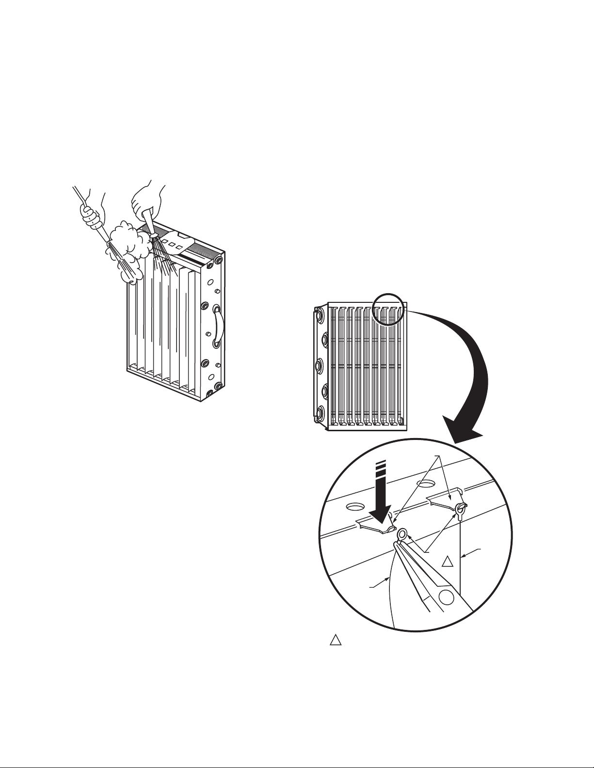
Replacing Ionizer Wires
Broken or bent ionizer wires can cause an electrical short to
ground, often resulting in visible arcing or sparking. Do not use
cells until broken wires are removed. Cells can be used
temporarily with one wire missing, but replace the wire as soon
as possible.
Replacement wires are supplied cut to length with eyelets on
both ends for easy installation. See Parts and Accessories Not
Illustrated section. To install:
1. Hook the eyelet on one end of the wire over the spring
connector on one end of the cell. See Fig. 15. Be careful
to avoid damaging spring connectors or other parts of
the cells.
2. Hold the opposite eyelet with a needle nose pliers and
stretch the wire the length of the cell. Depress the
opposite spring connector and hook the eyelet over it.
3. Check the cell for short circuits using an ohmmeter; see
Fig. 16. Check the resistance between the frame of the
cell and both the ionizer and the collector contacts. In
each case, the resistance should be infinite.
Fig. 14. Washing cells at car wash.
Reinstall the Cells and Prefilters
1. Inspect the cells for broken ionizer wires and bent collec-
tor plates. Repair as necessary or take to a
Honeywell Authorized Air Cleaner Repair Station.
2. Slide the prefilters into the upstream prefilter guides.
3. Slide in the air cleaner cells so the airflow arrow points
downstream and the handles faces outward.
4. Firmly close the access door.
5. Turn on the air cleaner. If the cells and prefilters are wet,
the neon light may not come on and you may hear
arcing. If the arcing is annoying, simply turn off the air
cleaner for two to three hours or until the cells are dry.
Replacing Media Postfilters
To maximize the filtration efficiency of the media postfilters,
replace them every six months. Replacement filters are
available in the same size and configuration as the original
unit. Contact your local Honeywell distributor to purchase
replacement filters. Install the replacement filters exactly as the
filters provided with the equipment. Use the Service Reminder
Schedule at the end of this document to help you establish and
maintain a regular replacement schedule. Keep your Service
Reminder Schedule in a convenient location.
Fig. 15. Replacing an ionizer wire.
68-0240EF—06 14
 Loading...