

Page 1
68-0138-2
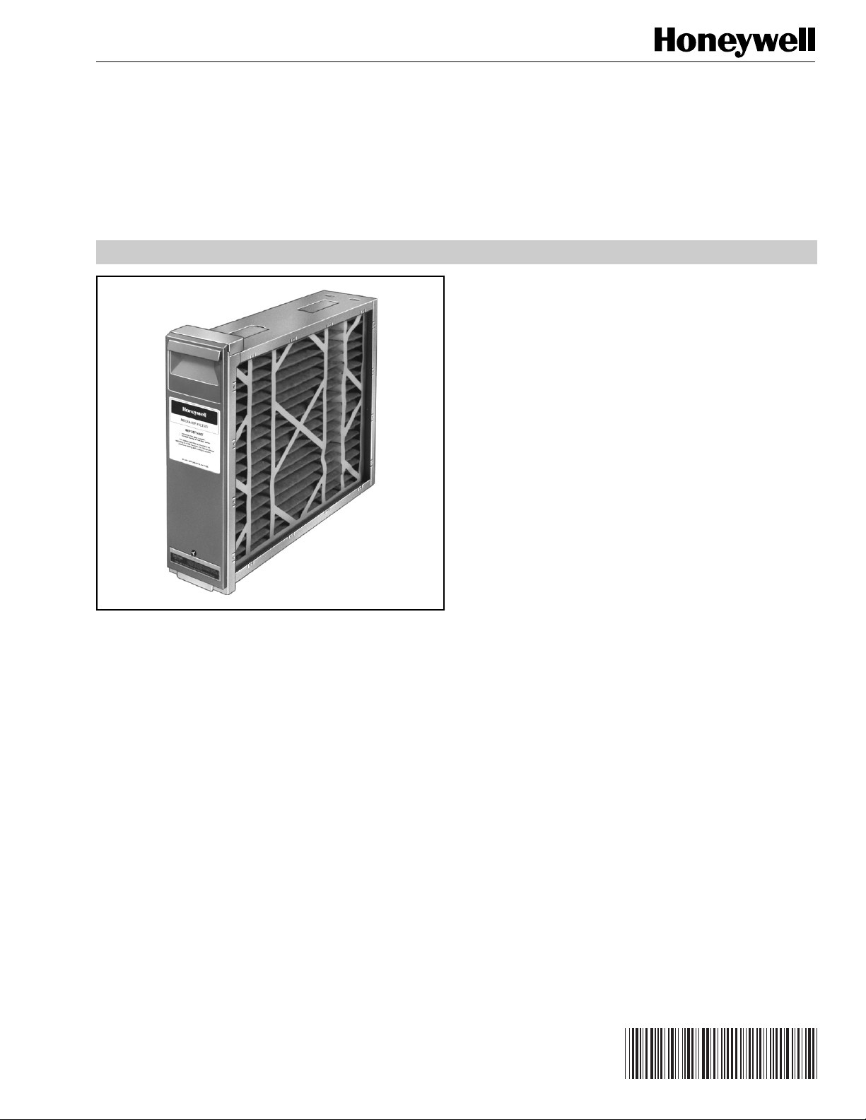
F25F
Media Air Cleaner
PRODUCT DATA
FEATURES
• High efficiency media filter captures particles as small
as 1.0 micron.
• Efficiency and arrestance ratings based on the
American Society of Heating, Refrigerating and Air
Conditioning Engineers Standard 52-76.
• Applicable to all gas, oil, and electric forced warm air
furnaces and to compressor cooling up to 3-1/2 tons.
Can be used with heat pumps only if the filter is
changed regularly to prevent excessive pressure drop.
Not recommended for applications where pressure
drop may be critical.
• Mounts in the return air duct.
• Cabinet can support weight of residential furnace and
evaporator coil.
APPLICATION
The F25 Media Air Cleaner captures a significant amount of
the air-borne particles from the air circulated through the unit.
• Requires no electrical connections.
• Mounts in any position.
• Requires no maintenance except periodic media filter
replacement.
• Media filter is easily replaced by homeowner.
• Later upgrade to F50 Electronic Air Cleaner is easy.
Contents
Application........................................................................... 1
Features .............................................................................. 1
Specifications ...................................................................... 2
Ordering Information ........................................................... 2
Planning the Installation ...................................................... 4
Installation and Checkout .................................................... 7
Future Option ...................................................................... 8
® U.S. Registered Trademark
Copyright © 1998 Honeywell Inc. • All Rights Reserved
Page 2

F25F MEDIA AIR CLEANER
SPECIFICATIONS
IMPORTANT
The specifications in this publication do not include
normal manufacturing tolerances; therefore, an
individual unit may not exactly match the listed
specifications. This product is tested and calibrated
under closely controlled conditions, and some minor
differences in performance can be expected if those
conditions are changed.
Model:
F25 Media Air Cleaner includes cabinet, access door and
pleated media filter.
Application:
Use with gas, oil, and electric forced warm air furnaces and
with compressor cooling. Can be used with heat pumps if
filter is changed regularly to prevent excessive pressure drop.
Not recommended for applications where pressure drop may
be critical.
Arrestance Efficiency:
Efficiency ratings are based on National Bureau of
Standards Dust Spot Method using atmospheric dust
and American Society of Heating, Refrigerating and AirConditioning Engineers Standard 52-76.
Initial Efficiency: 10 percent (staining dirt removal).
Average Efficiency: 18 percent (staining dirt removal).
Average Arrestance: 90 percent (bulb dirt removal).
Filter Media:
Nonwoven, reinforced cotton and synthetic fabric, pleated for
greater media area. See Table 1.
Capacity And Pressure Drop:
See Table 1.
Temperature Rating:
-40° to +125°F (-40° to +52°C).
Dimensions:
See Fig. 1.
Mounting:
Mounts in any position in the return air duct next to the
furnace blower compartment. Air flow must be in the direction
of the arrow on the filter cartridge. Cabinet is sturdy enough to
support weight of a residential furnace and evaporator coil.
Underwriters Laboratories, Inc.:
Listed to UL 900, Class 2.
The F25F removes particles as small as one micron. See
Fig. 1 for size ranges of common household particles.
ORDERING INFORMATION
When purchasing replacement and modernization products from your TRADELINE® wholesaler or distributor, refer to the
TRADELINE® Catalog or price sheets for complete ordering number.
If you have additional questions, need further information, or would like to comment on our products or services, please write or
phone:
1. Your local Home and Building Control Sales Office (check white pages of your phone directory).
2. Home and Building Control Customer Logistics
Honeywell Inc., 1885 Douglas Drive North
Minneapolis, Minnesota 55422-4386
In Canada—Honeywell Limited/Honeywell Limitée, 35 Dynamic Drive, Scarborough, Ontario M1V 4Z9.
International Sales and Service Offices in all principal cities of the world. Manufacturing in Australia, Canada, Finland, France,
Germany, Japan, Mexico, Netherlands, Spain, Taiwan, United Kingdom, U.S.A.
68-0138—2
2
Page 3
F25F MEDIA AIR CLEANER
Upgrade Path:
The F25 uses the same cabinet as the F50 Electronic Air
Cleaner. Upgrade requires installing the cell key, electronic
cells, protective screens and installation and wiring of the
power box.
Accessory:
S830A Clogged Filter Indicator.
Replacement Media:
Replace media filter annually or more often if reduced air flow
results in lower heating/cooling equipment performance.
Nominal Size (in.) Part Number
12.5 x 20 203722
16 x 25 203719
20 x 25 203720
20 x 20 203721
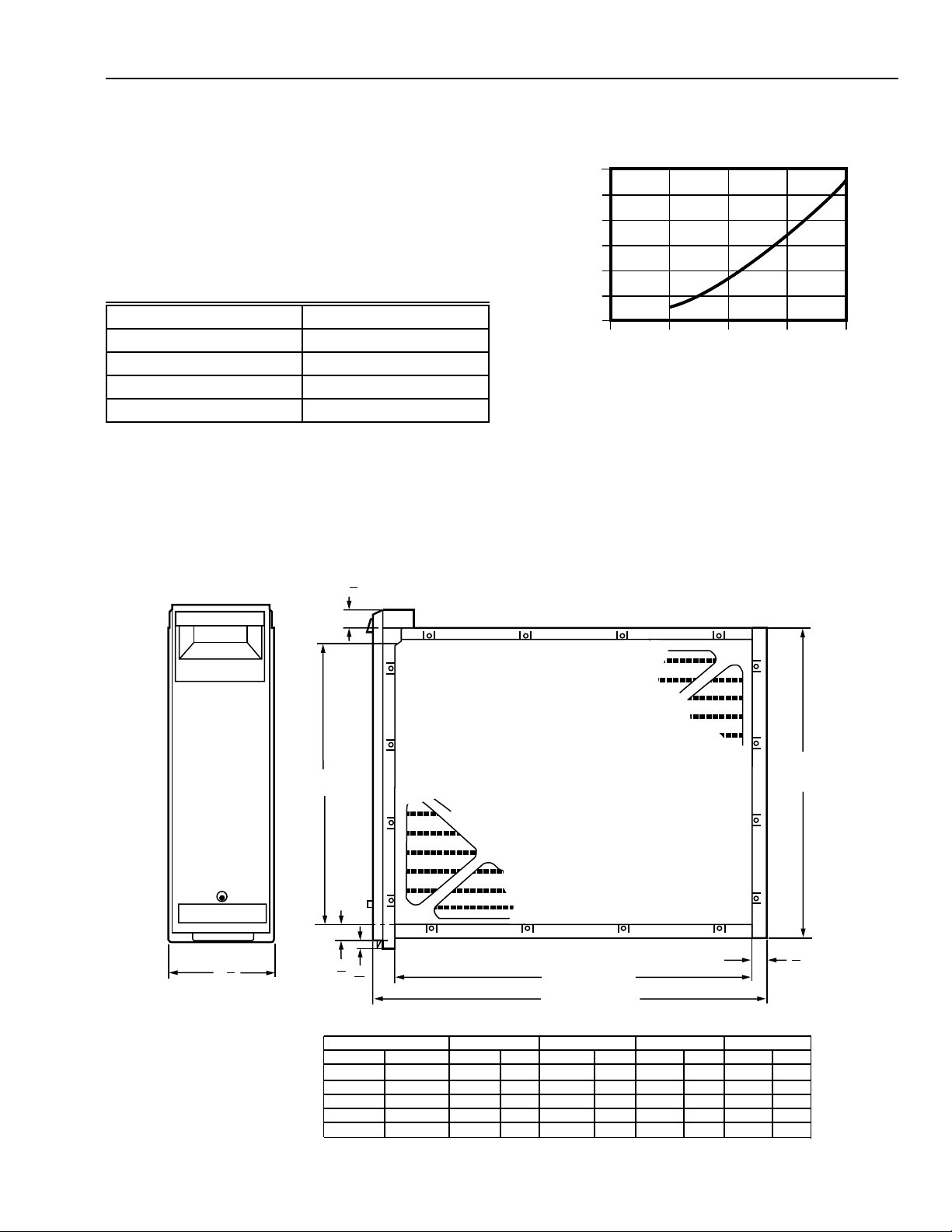
Table 1. Capacity, Pressure Drop and Area of
F25 Filter Media.
F25 FILTER PRESSURE DROP
0.30
a
0.25
0.20
0.15
0.10
0.05
PRESSURE DROP (IN. WC)
0.00
SIZE
12.5 X 20
16 X 25
20 X 25
20 X 20
a
When first installed. Pressure drop increases as filter
0
b
-------
-------
-------
-------
ABOVE IS WHEN FIRST INSTALLED. PRESSURE DROP INCREASES
AS FILTER BECOMES LOADED.
437.5 875 1312.5
AIRFLOW (CFM)
218
350
438
350
438
700
875
700
c
656
1050
1313
1050
1750
875
1400
1750
1400
M5638
becomes loaded. Filter should be replaced when pressure
drop reaches 0.5 in. w.c. (0.1 kPa).
b
Available in United States only.
c
Maximum capacity based on 500 FPM face velocity.
6
(171)
1
(29)
1
8
DIM. A
(SEE TABLE)
(22)
7
5
8
8
(16)
DIM. C (SEE TABLE)
DIM. D (SEE TABLE)
3
4
DIM. B
(SEE TABLE)
7
8
(22)
F25 SIZE
IN.
16 X 25
16 X 20
20 X 25
20 X 20
20 X 12 1/2
MM
406 X 635
406 X 508
508 X 635
508 X 508
508 X 318
DIM. A
IN. MM IN. MM
14 7/16
14 7/16
18 7/16
18 7/16
18 7/16
367
367
468
468
468
DIM. B
16 3/16
16 3/16
20 3/16
20 3/16
20 3/16
411
411
513
513
513
DIM. C
IN. MM IN. MM
23 1/4
18 1/4
23 1/4
18 1/4
10 7/8
Fig. 1. Installation dimensions in in. (mm) of air cleaner.
3
591
457
591
457
276
25 1/2
20 1/2
25 1/2
20 1/2
13 1/8
DIM. D
648
521
648
521
333
M5641A
68-0138—2
Page 4

F25F MEDIA AIR CLEANER
M939A
PLANNING THE INSTALLATION
Location
The media air cleaner should be installed where all the air
passing through the system is circulated through it. The best
location is in the return air duct next to the blower
compartment so the media air cleaner can help to keep the
blower motor and evaporator coils clean. Do not mount in the
supply air duct.
For most efficient air cleaning, spread airflow evenly across
the face of the media. If the duct is a different size than the
media air filter cabinet, gradual transitions are required. If the
duct turns sharply just before the air filter, turning vanes are
required.
Choose a location that is readily accessible for checking and
replacing the filter. Allow at least 26 in. (660 mm) clearance in
front of the unit for removal of the cartridge.
Install the media air filter where the temperature will not
exceed the ratings in the Specifications.
Fig. 2. Highboy furnace, with side installation.
Media air filter is mounted vertically where return
enters side inlet of furnace.
Applications With Air Conditioning
Mount the media air cleaner upstream of the evaporator coil
in a cooling system. The filter will help to keep the coil clean
and reduce maintenance.
Applications With A Charcoal Filter
Add an activated charcoal filter to the air handling system to
remove gaseous (nonparticulate) contaminants from the
circulated air. A common residential application is to remove
odors that cannot be removed by mechanical air filters. The
activated charcoal filter, if used, should be installed
downstream from the media air filter to protect the charcoal
filter from lint and other particles.
Applications With A Humidifier
The media air cleaner is compatible with humidifiers. Avoid
applications where water mist will reach the media. If an
atomizing humidifier is used, the filter media will require
replacement more often because of minerals in the water.
Choose Mounting Position
The media air cleaner can be mounted in any position, but the
arrow on the cartridge must point in the same direction as the
airflow. See Figs. 2-9 for proper location of the media air
cleaner for a variety of furnace installations. Note that the
media air cleaner cabinet is sturdy enough to easily support
the weight of the furnace and evaporator coil. See Fig. 3.
M940A
Fig. 3. Highboy furnace, with installation beneath furnace.
Media air cleaner is mounted horizontally where return
enters from below.
68-0138—2
4
Page 5

M941A
Fig. 4. Highboy furnace, with closet installation. Media air
cleaner is mounted vertically on furnace between furnace
and louvered return air opening in closet door.
F25F MEDIA AIR CLEANER
M942A
Fig. 5. Lowboy furnace, with media air cleaner mounted
horizontally in return plenum just above furnace and
opposite heating plenum.
M943A
Fig. 6. Counterflow furnace, with media air cleaner
mounted horizontally in return duct or plenum just
above furnace.
M944A
Fig. 7. Central fan installation, with media air cleaner
mounted horizontally in central return duct.
5
68-0138—2
Page 6

F25F MEDIA AIR CLEANER
Offsets
If the duct connection to the furnace in a side installation
allows less than 7 in. (178 mm) for mounting media air
cleaner cabinet, attach an offset to the elbow. See Fig. 12.
DUCT SIZE CHANGED GRADUALLY TO PREVENT TURBULENCE.
20 DEGREE EXPANSION PER SIDE PER
FITTING (4 IN. PER RUNNING FOOT
[100 MM PER 300 LINEAR MM])
M945A
Fig. 8. Horizontal furnace, with media air filter mounted
vertically in return duct near furnace.
M946A
Fig. 9. Two or more media air cleaners used in a high
capacity system.
Determining Sheetmetal Requirements
The media air cleaner is adaptable to all new or existing
forced air heating and cooling systems used in residential
applications. Transitions or turning vanes may be required in
some applications for effective media air cleaner operation.
Transitions
Tr ansitions are needed when the duct is a different size than
the media air cleaner cabinet. Follow these guidelines when
fabricating:
1. Use gradual transitions to reduce air turbulence and
increase efficiency. See Fig. 10.
2. Use no more than 20 degrees (about 4 in. per running
ft. (100 mm per 300 linear mm)) of expansion on each
side of a transition fitting.
Turning Vanes
If the media air cleaner is installed next to an elbow or angle
fitting, add turning vanes inside the angle to distribute airflow
more evenly across the face of the media. See Fig 11.
RETURN AIR
DUCT
TRANSITION FITTING
MEDIA AIR CLEANER CABINET
M947B
Fig. 10. Duct size changed gradually to prevent
turbulence.
TURNING
VANES
M5651
Fig. 11. Turning vanes installed in bend help distribute
airflow evenly over face of media.
LESS
THAN
7 in.
(178 mm)
OFFSET
AT LEAST
7 in.
1
(178 mm)
68-0138—2
1 REQUIRED TURNING VANES HELP DISTRIBUTE AIRFLOW EVENLY.
Fig. 12. Typical use of duct offset to make room for
media air cleaner.
6
M948A
Page 7

F25F MEDIA AIR CLEANER
INSTALLATION AND CHECKOUT
When Installing this Product…
1. Read these instructions carefully. Failure to follow them
could damage the media air filter or cause a hazardous
condition.
2. Check the ratings given in the instructions and on the
media air cleaner to make sure the product is suitable
for your application.
3. Installer must be a trained, experienced service
technician.
Remove Furnace Filter And Clean Blower
Compartment
Before starting the installation, remove and discard the
existing furnace filter (if used). Thoroughly clean the blower
compartment. If possible, power vacuum the ductwork to
remove accumulated dust in an occupied home or remove
construction dirt in a new home. The media air cleaner cannot
remove dirt that has settled in the blower compartment and
distribution ducts.
Install The Cabinet
The following procedure describes a typical side installation
on an existing highboy furnace. Alternate procedures are
noted as appropriate. Other changes in installation
procedures may be necessary to complete your installation.
Review The Installation Plan
Temporarily place the cabinet on the floor, oriented as it will
be when installed. Insert and remove the cartridge to make
sure the plan allows adequate clearance for easy removal
and replacement of the cartridge.
Make sure that shop-fabricated sheetmetal components, such
as turning vanes, are available.
Fasten The Cabinet To The Furnace
Fasten Cabinet To Ductwork
Fasten side of cabinet to the ductwork using sheet-metal
screws, rivets, or slip joints, as appropriate.
Connect Ductwork
Connect the vertical duct section to the elbow. If the vertical
drop of the duct is less than 7 in. (178 mm) from the side of
the furnace, shorten the horizontal trunk or attach an offset
fitting to the elbow. See Fig. 12. When ductwork is properly
aligned, connect the vertical duct to the horizontal trunk.
Seal Joints
Seal all joints in the return air system between the media air
filter and the furnace to prevent dust from entering the clean
airstream.
Install Filter Cartridge
Slide the filter cartridge into the cabinet, making sure the
arrow on the cartridge points in the direction of air flow.
Replace access door. Insert the tab on the bottom of the door
into the slot in the cabinet. Swing the door closed and press it
into place.
Checkout
Visually check the installation. Make sure:
• Airflow is in the direction of the arrow on the media air filter
cartridge.
•Turning vanes and transitions, if used, are properly
installed.
• Joints in sheetmetal between media fir filter and fur-nace
are sealed.
• All sheetmetal connections are complete.
•Original furnace filter has been removed and blower
compartment is cleaned.
Replace any access doors removed during the Installation or
Checkout.
Align the cabinet with the return air opening. Place blocks
under the cabinet, as necessary, to make sure the unit sits
securely. Create an opening in the furnace to match the
cabinet opening. Attach the cabinet securely to the furnace.
Attach the unit directly or fit a starting collar in the furnace
opening. Either drill holes and fasten with sheetmetal screws
or rivets, or use slip joints. If you are drilling holes, use a
locking pliers to help hold the unit in place during drilling.
Install Turning Vanes
Install turning vanes to help distribute air equally over the full
surface of the upstream side of the media. Install them
whenever an abrupt 90 degree elbow is installed directly
against the media air cleaner cabinet.
Run the furnace or cooling system through one complete
cycle to make sure the system operates as desired.
Maintenance
The media filter must be replaced when pressure drop across
the media filter reaches 0.5 in. w.c. (0.1 kPa). or at least
annually. If the media air cleaner is installed downstream from
an atomizing humidifier or if the installation includes both
heating and cooling, more frequent replacement may be
necessary. Clogged media must be replaced promptly to
avoid restricting airflow and reducing efficiency of the heatingcooling system. Record the replacement date in the space
provided on the replacement media filter.
See Replacement Parts in the SPECIFICATIONS section. If
desired, install the S830A Clogged Filter Indicator to allow
visual indication of when the media needs replacing. Install
and adjust the S830A by following the instructions provided
with the unit.
7
68-0138—2
Page 8

F25F MEDIA AIR CLEANER
FUTURE OPTION
The F25 Media Air Filter cabinet and filter cartridge are
designed to be easily upgraded to an F50 Electronic Air
Cleaner. An electronic air cleaner has the features to
increase the comfort and enjoyment of your home.
• Captures up to 95% of airborne particles 0.5 microns and
larger that pass through the unit.
• Can save 10 to 15% in operating costs over the life of your
equipment. Honeywell offers an exclusive
10-year Clean Coil Guarantee.
• Protects your expensive HVAC equipment.
• No on-going filter replacements because cells can be
washed and restored to top efficiency.
• Increased home comfort.
• Easy maintenance.
• And it’s by Honeywell, a leader in indoor air quality
products for over 30 years.
High Efficiency Cleaning
F50 Electronic Air Cleaner
Home and Building Control
Honeywell Inc.
Honeywell Plaza
P.O. Box 524
Minneapolis MN 55408-0524
Honeywell Latin American Region
480 Sawgrass Corporate Parkway
Suite 200
Sunrise FL 33325
68-0138—2 L.C. Rev. 2-98
68-0138—2
Home and Building Control
Honeywell Limited-Honeywell Limitée
155 Gordon Baker Road
North York, Ontario
M2H 3N7
Honeywell Europe S.A.
3 Avenue du Bourget
1140 Brussels
Belgium
Printed in U.S.A. on recycled
paper containing at least 10%
post-consumer paper fibers.
8
Honeywell Asia Pacific Inc.
Room 3213-3225
Sun Hung Kai Centre
No. 30 Harbour Road
Wanchai
Hong Kong
www.honeywell.com/yourhome
 Loading...