

Page 1
Ex-Schaltgeräte für Temperaturschalter
Ex switch units for temperature switches
Montage- und Bedienungsanleitung
Assembly- and Operating Instructions
f
Die Montage- und Bedienungsanleitung gilt speziell für die Ex-Ausführung der FEMA-Temperaturschalter. Zusätzlich sind die Hinweise in der
ebenfalls beigefügten Montage- und Bedienungsanleitung für das jeweilige Grundgerät (nicht Ex) zu
beachten.
The assembly- and operating instructions apply
specifically to the Ex-range of FEMA temperature
switches. You should also adhere to the assemblyand operating instructions for the
respective basic unit.
D
GB
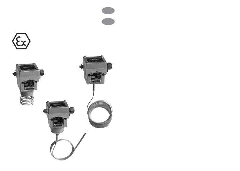
EX-FT
EX-TAM
EX-TRM
Page 2

2
Zündschutzart
II 2 G D EEx de IIC T6 IP65 T80°C
Zulassung
PTB 02 ATEX 1121
Ex-Zone
Geeignet für Zone 1 und 2, 21 und 22
Schutzart
IP 65 bei senkrechter Einbaulage
Umgebungstemperatur
-15 °C bis +60 °C
Max. Temperatur am Schaltgerät
60 °C
Kabeleinführung
M16 x 1,5, nur für feste Verlegung
Justierung: Skalenwert entspricht dem unteren
Schaltpunkt, der obere Schaltpunkt ist um die
Schaltdifferenz höher.
Schaltelement: Mikroschalter, einpolig umschaltend. Bei Verwendung als Begrenzer mit
Wiedereinschaltsperre muss die Verriegelung
durch die nachfolgende Schaltung erfolgen.
Einbaulage: senkrecht nach oben.
D
Type of Ex-protection
II 2 G D EEx de IIC T6 IP65 T80°C
Authorisation
PTB 02 ATEX 1121
Ex-Zone
Compatible for zones 1 and 2, 21 and 22
Form of protection
IP 65 (vertical positon)
Ambient temperature
-15 °C to +60 °C
Max. temperature at pressure switch
60 °C
Cable insert
M16 x 1.5, only for stationary installation of cable
Switching difference: Not adjustable,
approximate values see type-overview.
Adjustment: Scale values represent the lowest
switching point, the highest switching point
being the switching difference higher.
Switching element: Single-poled, changeover
microswitch.
Fitting position: vertically upwards.
GB
Technische Daten
der Ex-Schaltgeräte
Technical data
of Ex switch units
Page 3
3
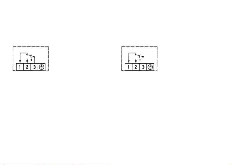
Anschlussplan
Die Klemmleiste ist nach Abnahme des Klemmenkastendeckels und der Klemmenschutzkappe zugänglich. Nach Anschluss der Zuleitungen Klemmenschutzkappe unbedingt
wieder anbringen.
Bei steigender Temperatur
wird die 3-1 unterbrochen
und 3-2 geschlossen.
Schutzleiteranschluss
Nach Abnahme des Klemmenkastendeckels
zugänglich.
Erdungsanschluss/Potentialausgleich
Außen am Schaltgerät. Max. Kabelquerschnitt
4 mm
2
Schaltleistung
Wechselstrom (AC): 3 A 250 V Widerstandslast,
2 A 250 V Induktive Last (cos = 0,6).
Gleichstrom (DC): 0,1 250 V~ Widerstandslast,
0,01 A 250 V~ Induktive Last,
2 A 30 V Widerstandslast.
Connection plan
The terminal board can be accessed after the
protective casing has been removed. After
connecting the supply lines, the protective
casing should in all cases be reattached.
With increasing temperature 3-1 and 3-2 are interrupted and closed.
Protection of the conductive connection
Can be accessed after removing the terminal
board casing.
Earthing connection/potential equalisation
External on the outside of the switching unit.
The maximal cross section of the cable is 4 mm
2
Switching power
AC: 3 A 250 V resistance load,
2 A 250 V inductive load (cos = 0.6).
DC: 0,1 A 250 V~ resistance load,
0,01 A 250 V~ inductive load,
2 A 30 V resistance load.
Page 4

4
1 Potentialausgleich
2 Klemmenschutzkappe (abnehmbar)
3 Anschlussklemmen
4 Kabeleinführung M16 x 1,5
Nur für feste Verlegung
5 Schaltpunkteinstellung
6 Feststellschraube für Einstellspindel
7 Schutzleiteranschluss
1 Potential equalisation
2 Protective casing for terminals (removable)
3 Connection terminals
4 Cable inlet M16 x 1.5
Only for stationary installation of cable!
5 Switching point adjustment
6 Locking bolt for setting spindle
7 Protection of the conductive connection
Page 5

5
Schaltpunkteinstellung
Der Schaltpunkt ist im Rahmen der im Datenblatt angegebenen Bereiche an der Stellspindel
mit einem Schraubendreher einstellbar. Dazu
ist der Klemmenkastendeckel abzunehmen
(4 Innensechskant-Schrauben M4 lösen). Zuvor
ist die kleine Feststellschraube an der Frontseite (oberhalb der Skala) zu lösen und nach
der Schaltpunkteinstellung wieder anzuziehen.
Rechtsdrehung an der Stellspindel bedeutet
niedriger Schaltpunkt, Linksdrehung bedeutet
höheren Schaltpunkt.
Die Skala dient als Richtwertskala, für genaue
Einstellungen ist ein Manometer erforderlich.
Serien-Nummer
Alle Schaltgeräte und die dazugehörigen Klemmenkastendeckel sind mit der Typenbezeichnung und einer Serien-Nummer gekennzeichnet. Bei der Montage ist darauf zu achten,
dass die Klemmenkastendeckel nicht
vertauscht werden.
Wichtig
Bei der Montage und Inbetriebnahme der ExSchaltgeräte sind die anerkannten Regeln der
Technik und Richtlinien für Installation in ExBereichen zu beachten.
Setting of switching point
The switching point can be set within the range
given in the datasheet by using a screwdriver
on the setting spindle. Additionally you should
remove the terminal board casing (with 4 hexagon screw M4). The affixing screw on the front
end (above the scale) has to be removed and
should be reattached after setting the switching
point.
By turning the setting spindle clockwise gives a
lower switching point, by turning anticlockwise
gives a higher switching point.
The scale should be used as a guide for more
exact settings you should use a Manometer.
Serial numbers
All switch units and their respective terminal
board casings are marked with a serial number.
When installing you should ensure that the
terminal board casing do not get mixed up.
Important notice
When installing the Ex switch units and setting
them up for operation you should comply with
the recognised rules and guidelines for
installations in Ex-areas.
Page 6

Page 7

Page 8

FEMA Regelgeräte FEMA Controls
Honeywell GmbH Honeywell GmbH
Böblinger Straße 17 Böblinger Straße 17
71101 Schönaich 71101 Schönaich
Deutschland Germany
Telefon +49 (70 31)6 37-02 Phone +49 (70 31)6 37-02
Telefax +49 (70 31) 637-8 50 Fax +49 (70 31) 637-8 50
7156.873/5
MU2B-0246GE51 R0707 www.fema.biz
Manufactured for and on behalf of the Environmental and Combustion Controls Division of
Honeywell Technologies Sàrl, Ecublens, Route du Bois 37, Switzerland
by its Authorized Representative:
 Loading...