

Page 1

Excel Web
EXCEL 5000 OPEN SYSTEM
USER GUIDE
® U.S. Registered Trademark EN2B-0289GE51 R0709
Copyright © 2009 Honeywell Inc.
All Rights Reserved
Page 2

EXCEL WEB USER GUIDE
Software License Advisory This document supports software that is proprietary to Honeywell Inc. and/or to third
party software vendors. Before software delivery, the end user must execute a
software license agreement that governs software use. Software license agreement
provisions include limiting use of the software to equipment furnished, limiting
copying, preserving confidentiality, and prohibiting transfer to a third party.
Disclosure, use, or reproduction beyond that permitted in the license agreement is
prohibited.
Trademark Information Echelon, LON, L
LonTalk, LonUsers, LonPoint, Neuron, 3120, 31701, the Echelon logo, the LonMark
logo, and the LonUsers logo are trademarks of Echelon Corporation registered in
the United States and other countries. LonLink, LonResponse, LonSupport, and
LonMaker are trademarks of Echelon Corporation.
BACnet is a registered trademark of the American Society of Heating, Refrigerating
and Air-Conditioning Engineers, Inc.
Microsoft and Windows are registered trademarks of Microsoft Corporation. Other
brands and their products are trademarks or registered trademarks of their
respective holders and should be noted as such.
ONMARK, LONWORKS, LonBuilder, NodeBuilder, LonManager,
EN2B-0289GE51 R0709 2
Page 3

USER GUIDE EXCEL WEB
CONTENTS
SOFTWARE AND FIRMWARE VERSIONS........................................................................................................................... 7
SYSTEM REQUIREMENTS ........................................................................................................................... 8
SYSTEM OVERVIEW ........................................................................................................................... 9
General .............................................................................................................. 9
Versions and Firmware ...................................................................................... 9
Browser Access / Operater Interface.................................................................. 9
Network .............................................................................................................. 12
Operation and Application Software ................................................................... 14
Backup/Restore.................................................................................................. 17
Diagnostics......................................................................................................... 17
System Architecture Examples........................................................................... 17
EXCEL WEB HTML INTERFACE ........................................................................................................................... 20
WEB BROWSER ACCESS VIA MODEM ........................................................................................................................... 21
Setup Modems ................................................................................................... 21
Make Modem Connection................................................................................... 22
WEB BROWSER ACCESS VIA SERIAL INTERFACE (RS 232)........................................................................................... 30
USER ADMINISTRATION ........................................................................................................................... 37
DATAPOINTS ........................................................................................................................... 40
Physical Datapoints............................................................................................ 40
Value Datapoints ................................................................................................ 41
Reference Datapoints......................................................................................... 41
Mapped Datapoints ............................................................................................ 42
Datapoint Properties........................................................................................... 42
Properties Descriptions.................................................................................. 43
Ackn. (Acknowledged Transitions) ................................................................ 44
Active / Inactive Text ..................................................................................... 44
Alarm Delay................................................................................................... 45
Alarm Text ..................................................................................................... 45
Alarm Type .................................................................................................... 45
Alarm Value................................................................................................... 46
Alarm Value Enable....................................................................................... 46
Auto ............................................................................................................... 46
BACnet Instance............................................................................................ 46
BACnet Object (Type).................................................................................... 47
BACnet Object ID .......................................................................................... 48
Change of Value Increment........................................................................... 49
Bit Mask......................................................................................................... 49
Bit String(s).................................................................................................... 49
Characteristic................................................................................................. 49
COV Period ................................................................................................... 50
Current Value ................................................................................................ 50
Datapoint Name............................................................................................. 50
Deadband ...................................................................................................... 51
Description..................................................................................................... 51
Descriptor ...................................................................................................... 52
Direction ........................................................................................................ 52
Engineering Unit ............................................................................................ 52
EOV / EOV Optimization................................................................................ 52
Event ............................................................................................................. 53
Event Enrollment ........................................................................................... 53
Event State.................................................................................................... 53
Fault............................................................................................................... 54
High Limit Enable .......................................................................................... 55
In Alarm ......................................................................................................... 55
Increment....................................................................................................... 56
Initial Value .................................................................................................... 56
3 EN2B-0289GE51 R0709
Page 4

EXCEL WEB USER GUIDE
Input NV ........................................................................................................ 57
IO Configuration ............................................................................................ 57
Is Alarm Condition ......................................................................................... 57
Is Fault Condition .......................................................................................... 58
Last Transition............................................................................................... 58
LON Point...................................................................................................... 58
Low Limit Enable ........................................................................................... 58
Manual .......................................................................................................... 59
Manual Life Safety......................................................................................... 59
Mapping......................................................................................................... 59
Notification Class........................................................................................... 60
Notify Type .................................................................................................... 60
NV Name....................................................................................................... 60
NV Type ........................................................................................................ 61
Out Of Service............................................................................................... 61
Output NV...................................................................................................... 62
Period............................................................................................................ 62
Priority Level.................................................................................................. 62
Polarity .......................................................................................................... 63
Property......................................................................................................... 64
Read Access Level........................................................................................ 64
Reference...................................................................................................... 64
Reliability....................................................................................................... 65
Relinquish Default ......................................................................................... 66
Reporting....................................................................................................... 66
Reset to......................................................................................................... 66
Runtime (Active Time)................................................................................... 67
Scaling Factor ............................................................................................... 67
State Text...................................................................................................... 67
States ............................................................................................................ 67
#States .......................................................................................................... 68
Time Delay .................................................................................................... 68
Time of Last Reset ........................................................................................ 68
Transition Events........................................................................................... 68
Type .............................................................................................................. 68
With Switches / 3 Position Output ................................................................. 69
Write Access Level........................................................................................ 69
Datapoint Properties Overview........................................................................... 69
Analog Input .................................................................................................. 70
Analog Output ............................................................................................... 72
Analog Value ................................................................................................. 74
Binary Input ................................................................................................... 76
Binary Output ................................................................................................ 78
Binary Value.................................................................................................. 80
Multi-State Input ............................................................................................ 82
Multi-State Output ......................................................................................... 84
Multi-State Value ........................................................................................... 86
Pulse Converter............................................................................................. 88
Reference Input............................................................................................. 90
Reference Output .......................................................................................... 90
I/O Pull-up Resistor Handling............................................................................. 91
I/O Initializiation.................................................................................................. 91
Input Datapoints (AI, BI) ................................................................................ 91
Output Datapoints (AO, BO).......................................................................... 92
Reference Inputs ........................................................................................... 92
Summary....................................................................................................... 92
Setting Datapoints into Manual Mode (Manual Override)................................... 93
Setting and Detecting Manual Overrides of Analog, Binary, and Multi-State
Outputs.......................................................................................................... 93
Setting and Detecting Manual Overrides of Analog, Binary, Multi-State,
and Pulse Inputs............................................................................................ 95
Status Flag Indications....................................................................................... 96
Input Point Status Flags ................................................................................ 96
Output Point Status Flags.............................................................................. 96
Alarm and Event Priority Classification .............................................................. 97
ALARM HANDLING ........................................................................................................................... 98
Alarm Behavior of Datapoints............................................................................. 98
EN2B-0289GE51 R0709 4
Page 5

USER GUIDE EXCEL WEB
Alarm Settings and Alarm Display for Analog Inputs and Outputs................. 101
Analog Input .................................................................................................. 102
Analog Output................................................................................................ 103
Analog Value ................................................................................................. 103
Binary Input ................................................................................................... 104
Binary Output................................................................................................. 104
Binary Value .................................................................................................. 105
Multi-state Input ............................................................................................. 105
Multi-state Output .......................................................................................... 106
Multi-state Value............................................................................................ 106
Pulse Converter............................................................................................. 107
Notification Class Manager................................................................................. 108
TIME PROGRAMS ........................................................................................................................... 111
Schedules and Calendars .................................................................................. 111
TRENDING ........................................................................................................................... 113
PLANTS ........................................................................................................................... 113
CONTROL LOOPS ........................................................................................................................... 113
Parameters.........................................................................................................114
Cycle Time Category..........................................................................................114
SYSTEM SETTINGS ........................................................................................................................... 114
Diagnostics.........................................................................................................115
EMAIL ALARMING ........................................................................................................................... 115
EVENT ENROLLMENTS ........................................................................................................................... 116
Event Enrollment Objects / Algorithmic Change Reporting ................................116
OPERATING THE EXCEL WEB
HTML INTERFACE ........................................................................................................................... 117
Start Excel Web HTML Interface........................................................................ 117
Main Screen Description and Basic Functions ................................................... 118
Main Screen Description................................................................................ 118
Basic Functions ............................................................................................. 122
User Administration ............................................................................................ 125
Invoke User Administration............................................................................ 125
Create Access Rights List.............................................................................. 126
Create User ................................................................................................... 127
Edit User........................................................................................................ 131
Delete User.................................................................................................... 132
Display Project Information................................................................................. 132
Display Controller Information ............................................................................ 133
Device Name ................................................................................................. 136
Display Plant Information ................................................................................... 136
Fast Access Lists ............................................................................................... 138
Create Fast Access List................................................................................. 138
View / Modify Fast Access List ...................................................................... 149
Delete Fast Access List ................................................................................. 151
Schedules........................................................................................................... 152
View Existing Schedules................................................................................ 152
Create Schedule............................................................................................ 153
Calendars........................................................................................................... 168
View Calendars ............................................................................................. 168
Create Calendar ............................................................................................ 169
Copy Calendar............................................................................................... 172
Edit Calendar................................................................................................. 174
Delete Calendar............................................................................................. 178
Show Calendar References........................................................................... 179
Datapoints .......................................................................................................... 180
View Datapoint List........................................................................................ 180
View / Edit Datapoint Details ......................................................................... 181
General Procedure ........................................................................................ 182
View General Properties................................................................................ 183
5 EN2B-0289GE51 R0709
Page 6

EXCEL WEB USER GUIDE
View / Edit Alarming ...................................................................................... 184
View / Edit Values ......................................................................................... 186
View / Edit Command Priorities..................................................................... 190
View / Edit Event Enrollment Alarming .......................................................... 191
System Settings ................................................................................................. 203
View/Change Clock Settings ......................................................................... 203
View/Change Cycle Time Categories............................................................ 204
View/Change Communication Settings ......................................................... 206
View LON Diagnostic Data............................................................................ 210
View BACnet Diagnostic Data....................................................................... 216
Search Using “Who Has”............................................................................... 216
Trend.................................................................................................................. 217
Alarms................................................................................................................ 229
View Alarm Details ........................................................................................ 231
Control Loops..................................................................................................... 234
View Control Loop Information ...................................................................... 234
Parameters.................................................................................................... 235
Change Parameter ........................................................................................ 238
Enable Event Enrollment Alarming..................................................................... 240
Enable Event Enrollment Alarming for Plant.................................................. 240
Enable Event Enrollment Alarming for Controller System Status .................. 243
Enable Event Enrollment Alarming for Controller Email Alarming ................. 245
E-Mail Alarming.................................................................................................. 248
AUTOMATIC SAVING OF ONLINE CHANGES..................................................................................................................... 255
Excel Web Controller and Communication Failures ........................................... 255
CONTROLLER OVERLOAD INDICATORS........................................................................................................................... 255
CONTROLLER BOOT AND WATCHDOG BEHAVIOR......................................................................................................... 256
TROUBLESHOOTING ........................................................................................................................... 258
Modem Trouble Shooting .............................................................................. 258
INDEX ........................................................................................................................... 259
EN2B-0289GE51 R0709 6
Page 7

USER GUIDE EXCEL WEB
SOFTWARE AND FIRMWARE VERSIONS
This user guide is valid for the following software versions:
• Linux 2.01.00
• Excel Web 2.01.09
• CARE 8.03.00
7 EN2B-0289GE51 R0709
Page 8

EXCEL WEB USER GUIDE
SYSTEM REQUIREMENTS
To operate the Excel Web HTML Interface via touch panel PCs or any other
standard PC platform, the following requirements must be fulfilled:
Web browser
• Internet Explorer 5.5 or higher, Netscape 6.2.1 or higher
• HTML 4.01
• CSS-1
• JavaScript 1.3
• DOM Level 1
• Frames
• Full screen
Touch panel PC Hardware
• Minimum 12,1“
• SVGA color display
• 800 x 600 dpi resolution or higher
• No cooling fan
• IP 54 or better
• Power supply: ideally 24V ACDC
250V AC or 24V DC acceptable
• 1 x Ethernet 10/100 Base Tx, RJ45
• 1 x USB (optional)
• 1 x RS232 (optional)
• Memory: no hard disc drive, 64 MB RAM or more
64 MB Compact Flash card or more.
• CE compliant
Operating system
• Internet Explorer 5.5 or higher pre-installed
• Soft keyboard in order to allow numeric and alphanumeric input
• Microsoft platform builder must use latest 2004 Microsoft QSEs for Internet
Explorer
• The following features of the operating system image must already be pre-
defined as factory defaults:
a. Internet explorer pre-set in auto-start group
b. Hyperlinks in Internet Explorer always underlined
c. Customer specific settings (see next paragraph) can be easily stored in the
registry
• A Honeywell service technician must be able to easily make the following
customer specific settings:
a. Network settings (IP address, Mask and Gateway)
b. Enter the customer’s Excel Web IP address as Start page for Internet
Explorer
EN2B-0289GE51 R0709 8
Page 9

USER GUIDE EXCEL WEB
SYSTEM OVERVIEW
General
The Excel Web® is a BACnet/IP-based, freely programmable building automation
controller.
Excel Web® incorporates the two major open standards in building automation:
BACnet® and L
As a native BACnet® building controller, Excel Web® integrates into any 3rd-party
BACnet® system and can integrate 3
Furthermore, Excel Web® is a full L
enabling you to use of Honeywell’s complete L
party LON products.
The Excel Web® can host a huge variety of building management applications, be it
traditional heating, ventilation, and air conditioning (HVAC) applications, energy
management functions, including optimum start/stop, night purge, and maximum
load demand, supervisory functions for lighting, sunblind, heat and energy metering
and many other applications.
By virtue of its "peer-to-peer" concept, Excel Web® is not dependent upon the
availability of super ordinate centrals or application network controllers.
Excel Web® seamlessly integrates into Honeywell’s Enterprise Buildings
Integrator™ (EBI) and SymmetrE® front-ends.
ONWORKS®.
rd
party BACnet devices and controllers.
ONWORKS® controller. This gives the benefit of
ONWORKS® product portfolio and 3
rd
-
Versions and Firmware
Excel Web Versions XL1000B50 / XL1000C50
52 physical datapoints and 50 Schedule Objects, 128 trend objects
XL1000B100 / XL1000C100
104 physical Datapoints and 50 Schedule Objects, 128 trend objects
XL1000B500 / XL1000C500
300 physical Datapoints and 50 Schedule Objects, 128 trend objects
XL1000B1000 / XL1000C1000
600 physical Datapoints and 100 Schedule Objects, 128 trend objects
For more details such as RAM size, please refer to Product Data EN0443-GE51.
Excel Web Firmware Linux operating system
Updating Firmware If, at some later point in time, i.e. after the release of a new version of the firmware,
XLWebExe-H-MM-LL.xwa, including firmware itself, BACnet driver and HTML pages
(H-MM-LL are version numbers).
the user wishes to download the new firmware into the Excel Web, this can be done
either via USB or Ethernet, using the CARE.
Browser Access / Operater Interface
Operator Interface The Excel Web® is operated via a standard web browser (Excel Web HTML
Interface). By default, an integrated web server provides all operation pages for a
full browser-based operation. Through the consequent use of software standards,
any PC platform can be used as an operator interface (client). In addition to laptops
and desktop PCs, panel PCs can also be used for direct flush mounting into panel
9 EN2B-0289GE51 R0709
Page 10
EXCEL WEB USER GUIDE
doors. Other than the operating system and Internet Explorer® or Netscape®, no
Alternatively – or in addition – Excel Web can be operated with the Excel Touch
Access Modes to
Excel Web Controller Any Excel Web controller on the network can be accessed via the browser-based
The controller can be accessed in one of the following ways:
software needs to be installed on the client PCs.
operator interface, which is a 5.7” touch-screen device (order number “XI882” For
more details please refer to the Excel Touch product data sheet, form no.
EN0B0615-GE51) or/and to the Excel Touch User Guide, form no.
EN2B0615-GE51).
Excel Web HTML Interface, both locally and remotely. The Excel Web HTML
Interface can reside on any PC platform client such as:
• Desktop PC
• Notebook, Laptop
• Touch panel PC
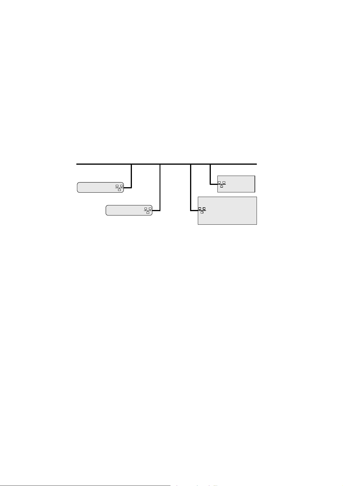
• LAN (remote access)
LAN
Excel Web Controller A
Excel Web Controller B
Fig. 1. Access to Excel Web controller via LAN
Excel Touch
BACnet Client
Desktop PC, Notebook
Permanent IP address, allocated by I.T. department
The Excel Web controller can be accessed remotely via LAN by allocating a valid
and permanent IP address to the controller, which is reachable within the LAN.
Procedure:
See Establish Remote LAN Connection section in CARE User Guide
EN2B0182GE51 / 74-5587.
Alias IP address, factory default
For access via Ethernet, the Excel Web has a permanent factory default IP
address 192.168.253.20 and Network Mask 255.255.255.0. Your PC's IP
address must match the Excel Web controller's default IP address. We
recommend using 192.168.253.21 and Network Mask 255.255.255.0.
When using this default address, you must ensure that you have only one
powered-up Excel Web controller on your Ethernet; otherwise, communication
will fail because all Excel Web controllers have the same permanent default IP
address. Alternatively, you can use an Ethernet cross-over cable between your
PC and the Excel Web controller rather than having your PC and the Excel Web
controller both connected to a LAN.
Standard Ethernet Interface of your PC
Change the (factory-set) configuration of the integrated Ethernet card so as to
match the Excel Web IP address and IP subnet.
NOTE:
In order to (subsequently) operate on your standard Ethernet network (again),
you will have to change the configuration back to the previous settings.
Dedicated Ethernet Interface of your PC
If the laptop or PC with which you wish to access the Excel Web via Ethernet/IP
is not already equipped with an integrated Ethernet Card, or if you want to leave
EN2B-0289GE51 R0709 10
Page 11
USER GUIDE EXCEL WEB
the IP settings of the integrated network card unchanged, you can buy and install
(into your laptop or PC) an external Ethernet network card.
• Crossover cable (local access)
Excel Web Controller A
LAN
Excel Web Controller B
Fig. 2. Access to Excel Web controller via crossover cable
Crossover Cable
BACnet Client
Notebook, Touch panel PC, Desktop PC
To locally connect to the Excel Web controller via Ethernet, a crossover cable
can be used. Hence it has temporarily no connection to any other network and
the Excel Web controller is not reachable in the network.
The crossover cable connection type has the highest transfer rate (100 Mbit/s),
but when applied, the IP address settings of the client need to be changed.
Procedure:
See Establish Local Ethernet Connection via Crossover Cable section in CARE
User Guide EN2B0182GE51 / 74-5587.
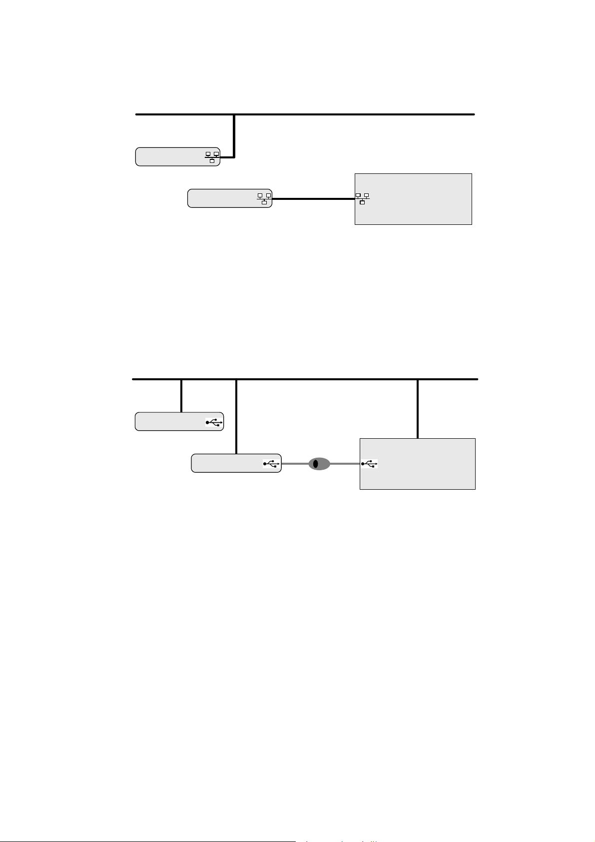
• USB (local access)
LAN
Excel Web Controller A
USB Cable
Excel Web Controller B
Desktop PC, Notebook, Touch panel PC
Fig. 3. Access to Excel Web controller via USB
BACnet Client
To locally connect to the Excel Web controller via USB interface, a D-Link DUB-
E100 USB 2.0 Fast Ethernet adapter can be used.
The USB connection type is recommended for the initial setup of an Excel Web
controller due to a reasonable transfer rate (2 Mbit/s) and because no IP address
changes are necessary after installation. In addition, the LAN connection can be
used in parallel and uninterruptedly.
Permanent IP address, factory default
For access via USB, the Excel Web has a permanent factory default IP address
192.168.252.20 and Network Mask 255.255.255.0. Your PC's IP address of the
Belkin USB network adapter must match the Excel Web controller's default IP
address subnet: We recommend using 192.168.252.21.
Procedure:
See Establish Local Connection via USB Cable section in CARE User Guide
EN2B0182GE51 / 74-5587.
IP Address Allocation
To establish any of the described connections, IP addresses must be allocated to
the relevant network components such as BACnet client, Excel Web controller(s)
and USB network adapter.
11 EN2B-0289GE51 R0709
Page 12
EXCEL WEB USER GUIDE
For further information, please refer to "Setup Excel Web Controller" section in
CARE User Guide EN2B0182GE51 / 74-5587.
• Internet (remote)
Firewall
Internet
BACnet Client
Desktop PC, Notebook
Provider
LAN
Excel Web Controller A
Fig. 4. Remote Access to Excel Web controller via Internet
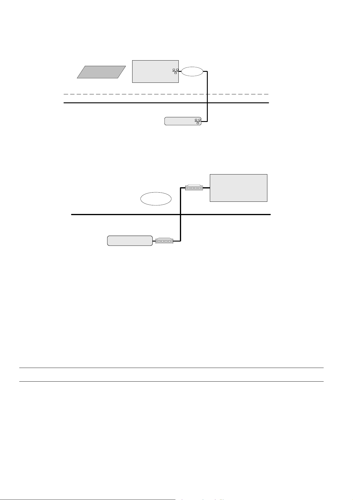
• Web Browser access to Excel Web controller via modem
Without using an Internet provider, dial up access via modem is possible by using
two modems. One must be connected to the telephone network at the Excel Web
controller and one at the BACnet client or PC with Internet Browser.
BACnet Client
Modem
Dial-up
Desktop PC, Notebook
Telephone network
Excel Web Controller A
Fig. 5. Web Browser access to Excel Web controller via modem
• CARE access to Excel Web controller via modem
You can work with CARE on an Excel Web controller via modem by connecting
remotely to the modem attached to the Excel Web controller. When the
connection is established, CARE can connect to the Excel Web controller via IP
address. LON-Commissioning can then be done by using a NIC IP (Loytec)
additionally.
Communication Settings Communication settings in the Excel Web HTML Interface comprise:
• Interface settings such as serial baudrates, IP address, neuron chip ID, MAC
address, automatic logout time of web server
• Modem settings
• Remote central (front-end) settings
Bus-Wide Operation Any user can operate all Excel Web controllers residing on a BACnet network.
Modem
Network
Based on its design as an IP device (see also "Communication Protocols"), the
Excel Web controller "speaks" BACnet over IP (Internet Protocol) and hence, can be
integrated smoothly and without the need for additional devices into any network
infrastructure having regard to the corresponding network security mechanism.
EN2B-0289GE51 R0709 12
Page 13

USER GUIDE EXCEL WEB
OSI Model
Application layer
TCP / IP Model BACnet over IP*
Presentation layer
Session layer
Transport layer Transport layer
Network layer Network layer
Data link layer
Physic al layer
Application layer
Link layer
IP *
BACnet *
Ethernet
Ethernet
BACnet
Functions
Protocol
Physical
Fig. 6. Networking model of Excel Web controller
Network Load The network load for one Excel Web controller in combination with one EBI central
is about 1 % network load in a 10 Mbit network.
These figures are based on the following assumptions:
• 20 BACnet properties per display
• BACnet properties are updated by 5 EBI displays simultaneously
• Each property is updated every 5 s. One update message for a simple property
needs 100 bytes, for a complex property 200 bytes.
Calculation:
5 displays * 20 properties/display * 150 bytes/property *
1 update/5 s = 30000 bits per second.
If alarms should be received and properties should be in trend, everything should
not consume more than 100 Kbits/s, which is 0,1 % in a 100 Mbit network.
Communication Protocols BACnet/IP - ISO 16484-5 – ENV 13321-1
Communication with other Excel Web® controllers, with 3
with Honeywell Enterprise Buildings Integrator™ and SymmetrE® front-ends, and
rd
with 3
-party BACnet® front-ends is based on the international BACnet® Protocol.
rd
-party BACnet® devices,
More details on the BACnet® Interoperability can be obtained from the Excel Web®
Protocol Implementation Conformance Statement (PICS).
LonTalk®
Communication with physical I/O modules, with room and zone controllers, and with
Excel 50/500 controllers is based on LonTalk®.
A Free Topology Transceiver (FTT-10A or FT-X1) allows a communication speed of
78 KBaud.
In typical cases, field devices are controlled via Honeywell Distributed I/O
(XFL52xB) or Smart I/O (XFCxxx) modules. Maximum cable lengths are 320 m to
2,200 m.
HTTP
Excel Web® can be operated using a standard Internet Explorer (5.5 or higher) or
Netscape (6.2.1 or higher). The required minimum screen resolution is 800 x 600
pixels. For more details, please refer to the "Operating the Excel Web HTML
Interface" section.
FTP
The firmware and application are downloaded via the standard FTP (File Transfer
Protocol).
Telnet
Telnet access to the Excel Web controller is possible for the purpose of service and
diagnostic of the Linux operating system and the Excel Web firmware. In case this is
needed, please contact your Honeywell representative.
13 EN2B-0289GE51 R0709
Page 14

EXCEL WEB USER GUIDE
SMTP
Simple Mail Transfer Protocol is used for the embedded Email alarming functionality
of Excel Web.
Time Synchronization BACnet clients such as EBI or 3
web controller via the standard time sync or UTC time sync BACnet service. When
having multiple Excel web controllers on a network without any BACnet client being
the time master, the time must be set for any controller separately and correctly
before downloading the application.
EBI Compatibility The Excel Web controller communicates with BACnet front-ends only.
Supported BACnet front-ends are:
• EBI / SymmetrE Software
For more information, please refer to the following software release bulletins:
− EBI R300.1 with Excel Web / BACnet Software Update
− SymmetrE R300.2 with Excel Web Software Update
− EBI / SymmetrE R310.1 or later
• XFI Software
The XFI has not been tested yet with Excel Web, but supports BACnet
functionality.
rd
-party BACnet front-ends, can time sync the Excel
Operation and Application Software
Programming The Excel Web® is freely programmable using the CARE Engineering Tool and is
This allows making use of standard, pre-tested and pre-documented application and
Application Control Four selectable control loop speed classes (multitasking) with defined cycle times
User Administration Your control system is protected by defined user access rights. This ensures that
Datapoints Datapoints are the basis of the Excel Web – BACnet system. Datapoints contain
Alarm Handling Alarm handling is defined and realized in the application.
thus ideal for all Building Control and Building Management tasks.
control strategies.
and switching tables allow tailored and highly effective applications control.
only authorized persons have access to the system data. There are six pre-defined
user levels. The predefined user levels are arranged hierarchically and the
sequence with descending priority is as follows:
• System Admin (128)
• Project Admin (115)
• Building Engineer (96)
• Operator (64)
• Tenant (32)
• Guest (0)
Excel Web® allows the definition of up to 128 user levels by default. The above
mentioned user levels are available. Each user level can have different read and
write rights assigned, e.g. Display Communication Settings, Create and Delete
Calendars, Change clock settings, etc. Several users with individual passwords can
be defined for each user level.
NOTE: There is no limit to the number of users per user level.
system-specific information such as values, status, limit values, and default settings.
The user has easy access to datapoints and the information they contain.
The user can recall and modify information in the datapoints.
EN2B-0289GE51 R0709 14
Page 15

USER GUIDE EXCEL WEB
BACnet alarming
On datapoint level, alarming is done by the BACnet intrinsic reporting service.
The following point changes may generate alarm messages:
• Exceeding limit values (analog points and pulse converter point)
• Changes of state (binary and multi-state input and value datapoints)
• Faults (due to, e.g. LON communication errors or e.g. sensors breaks)
Alarming is further supported by notification class objects, which contain information
required for the distribution and segregation by time and addresses of alarm/event
notifications within a BACnet system.
Notification class objects allow up to 256 alarm priorities. By default, CARE provides
3 notification class objects matching the EBI alarm priorities:
• Urgent
• High
• Low
IMPORTANT
The internal ring alarm buffer takes max. 100 alarms.
Excel Web does also support the BACnet algorithmic alarming service.
The algorithmic alarming uses the standard BACnet “Event Enrollment Object” and
is used to provide the following functionality:
• Warning limits for analog datapoints (Min. and Max. warning limits, in
addition to the Min and Max Alarm limits)
• Alarming for datapoint change between “auto” and “manual”
• Alarming for missing or late acknowledgement of alarms
• Maintenance alarming, based on elapsed runtime of datapoints or number
of state-changes of datapoints.
• Alarming for unsuccessfull transmission of Email alarms
• Alarming for stopped or started plants within Excel Web
LON alarming
As LON does not know "devices" but only NVs, I/O module alarming must be
realized by mapping a particular NV to the appropriate "alarm" datapoint in CARE.
Then for the alarm datapoint, the alarm settings are to be defined as usual.
Remote LON Commissioning Excel Web Controllers on a LON bus can be commissioned remotely via LAN / WAN
Time Programs Time programs comprise schedules and calendars.
Schedules
Schedules are daily and weekly time programs.
Whenever you want, you can use schedules to enter the setpoint or status for any
Schedules are assigned to plants. Each plant of a controller can have multiple
using CARE or Excelon (can be used as LonWorks protocol analyzer via LAN).
datapoint.
schedules assigned and each schedule can command datapoints of that plant.
Each schedule specifies a list of datapoint properties to command (switchpoints) on
a weekly basis. The week program defines the normal daily activity of the system by
specifying which switchpoints are to be commanded each day of the week. The
week program applies to a definable time period. There is only one-week program
per schedule.
Schedules offer 16 write priorities that define the priority for writing to the present
value of output and value datapoints. Note that only priorities 9 to 16 are allowed in
the controller.
The write priority applies only to the present value property of virtual points and
output points. The write priority is ignore
d for all other types of properties.
15 EN2B-0289GE51 R0709
Page 16

EXCEL WEB USER GUIDE
For every schedule (week program), specific programs called exceptions can be
created. Exceptions have higher priority than the week program and will overwrite
the week program for a definable time period. Exceptions can be one of the
following four time periods:
• Specific Date
e.g. Christmas Eve or 5.5., the whole of May, or the whole year of 2004
• Date Range
e.g. Summer holidays from 29.7-7.9.2004
• Recurring Event
e.g. every last Friday of every month
• Calendar Reference
A project-wide calendar provides dates, e.g. regional holidays and
public/religious festivals or any other particular date. The time period can be a
specific date, a date range or a recurring event.
Calendars contain exception days or periods, e.g. Christmas, holidays. Calendars
Trending Trending can be performed via the Excel Web HTML Interface residing on any PC
Controller Based Trending A Compact Flash Card (type 1 or type 2) or micro drive allows memory extensions
Protocolling In the context of the Excel Web controller, "protocolling" means creating a log of the
Calendars
are valid for the whole project, and are executed in each controller but apply only to
those schedules, which reference calendars. Changes in multiple particular
controller schedules can be quickly made by simply changing a calendar in one
controller. Thus project-wide scheduling can be influenced.
platform and via BACnet clients. Trend data is stored on an 2 MB integrated Flash
memory which can hold a maximum of 64,000 trend records distributed among 125
trend log objects. In addition, three trend log objects are used for LON statistic
trending. A single trend log object can include max. 2.880 trend records (max. trend
buffer size). One trend record equals 30 bytes. Extended trend memory is possible
by using a 3
rd
-party standard Compact Flash card or micro drive. Trend data storage
can be in ´Ringbuffer` mode or in ´Stop When Full` mode. Trend data are
dynamically created in the controller and can be saved in a .CSV file.
Trend data have unlimited lifetime and survive an application download. Trend
objects must be explicitly deleted via Excel Web HTML Interface or BACnet. This
deletes also the corresponding trend records. The trended object may be a local or
a reference point in the same controller and the trended property may be integer or
floating point, e.g. point value, point state, alarm limit, time stamp.
Trending via BACnet Client
BACnet clients like EBI will use the BACnet ´read range service` to readout trend
values from the Excel Web controller. Trend recovery for BACnet clients, specifically
EBI and SymmetrE optionally provide an automated recovery mechanism which
allows to "backfill" missing trend data on the BACnet client side with trend values
from the Excel Web controller.
for the purpose of expanding integrated trend memory and increasing historical data
storage. The integrated on-board trend memory allows saving of max. 64.000 trend
values.
values or states of the datapoints, which have been assigned to this particular Excel
Web controller. Using the Excel Web HTML Interface, the user must place the
corresponding datapoints into "trend". If, at some later point in time, i.e. after lengthy
operation, a protocol of the Excel Web controller's history is desired, the
corresponding trend data can be generated, viewed, and downloaded (in CSV
format) via the browser interface. For the storage of larger amounts of trend data
(more than 64,000 trend entries – corresponding to approx. 2 MB), a CF card or
micro drive can be used. The trend data can even be downloaded into a BACnet
client if this client supports this BACnet service.
When connected to the Excel Web controller via Internet Browser, all other Excel
Web controllers of the same project can be operated without the necessity of a new
login.
EN2B-0289GE51 R0709 16
Page 17

USER GUIDE EXCEL WEB
Backup/Restore
The Excel Web controller supports the BACnet Backup/Restore functionality by the
backup/restore of the application files.
When performing a backup/restore of the application files, the following must be
noted:
• Online changes may not be considered circa 1 minute before the backup is
started.
• Do not restore the application if the LON interface of the controller has been
changed via CARE.
Diagnostics
LON Diagnostics The Excel Web HTML Interface allows trending and display of LON specific
parameters, e.g. messages received and transmitted, communication errors, etc.
BACnet Diagnostics The Excel Web HTML Interface allows display and analysis of BACnet services
Modem Diagnostics Modem diagnostics is based on open LINUX and the Excel Web offers the standard
which have been initiated or executed by Excel Web.
Furthermore the Excel Web HTML I/F allows searching for BACnet objects in a
BACnet network.
LINUX modem log functionality.
System Architecture Examples
See next pages.
17 EN2B-0289GE51 R0709
Page 18

EXCEL WEB USER GUIDE
Laptop
Modem
Dial-up***
Analog / ISDN
MODEM
LAN / WAN
*** Dial-up not recommended due to network security
problems. If applied, please contact the network
administrator for security measures!.
LonWorks
Laptop
Internet
Modem / ISDN / DSL
PROVIDER
Touch Panel PC
Firewall
LON
Modem
LON
LON
Excel Web
CF
321
Excel Web
CF
LON
321
Smart I/0 Modules
Fig. 7. Open BACnet / LON System Architecture for Plant Control
Desktop PC
LON
LON
Excel Web
CF
321
Router
LON
LON
Excel Web
Field Devices
Central (EBI)
CF
321
3rd-Party BACnet Devices
3rd-Party LON Devices
EN2B-0289GE51 R0709 18
Page 19

USER GUIDE EXCEL WEB
LAN / WAN
*** Dial-up not recommended due to network security
problems. If applied, please contact the network
administrator for security measures!.
LonWorks
Laptop
Modem
Dial-up***
Analog / ISDN
MODEM
Laptop
Internet
Modem / ISDN / DSL
PROVIDER
Touch Panel PC
Firewall
LON
Modem
LON
LON
21
Excel Web
CF
3
Excel 12 Controllers
Excel Web
CF
LON
321
Excel 10 Controllers
Fig. 8. Open BACnet / LON System Architecture for Room Control
Desktop PC
LON
LON
Excel Web
°
+
Router
CF
321
LON
LON
21
Excel Web
Field Devices
Central (EBI)
CF
3
3rd-Party BACnet Devices
3rd-Party LON Devices
19 EN2B-0289GE51 R0709
Page 20

USER GUIDE EXCEL WEB
EXCEL WEB HTML INTERFACE
The Excel Web® controller is operated via a standard web browser.
By default, an integrated web server provides all operation pages for a full browserbased operation.
Through the consequent use of software standards, any PC platform can be used as
an operator interface (client). In addition to laptops, desktop PCs or panel PCs can
also be used for direct flush mounting into cabinet doors (IP65).
Other than the operating system and Internet Explorer® or Netscape®, no software
needs to be installed on the client PCs.
For detailed information on the operation of the Excel Web HTML Interface, please
refer to the "Operating the Excel Web HTML Interface" section, p. 117.
20 EN2B-0289GE51 R0709
Page 21

USER GUIDE EXCEL WEB
WEB BROWSER ACCESS VIA MODEM
Without using an Internet provider, dial up access to the Excel Web controller via
modem is possible by using two modems. One must be connected to the telephone
network at the Excel Web controller and one at the BACnet client or PC with Internet
Browser.
http://192.168.253.20
Excel Web
Controller
IOIO 3
Modem
Fig. 9. Web Browser access to Excel Web controller via modem
Connect the Westermo TDW 33 modem to the port 3 of the Excel web controller and
to the telephone network.
Connect and install a Westermo TDW 33 modem or a comparable model of another
manufacturer according to the relevant modem documentation and the Microsoft
Windows documentation. After successful installation, the modem must be available
in the Phone and Modem Options program group of the Control Panel.
Telephone Network
Modem
COM
Notebook, Touch panel PC, Desktop
PC
Setup Modems
21 EN2B-0289GE51 R0709
Page 22

EXCEL WEB USER GUIDE
Make Modem Connection
NOTE: The following description applies to Windows XP. For Windows 2000, the
screenshots and options are similiar. Please refer to the Windows XP
Online Help for detailed descriptions.
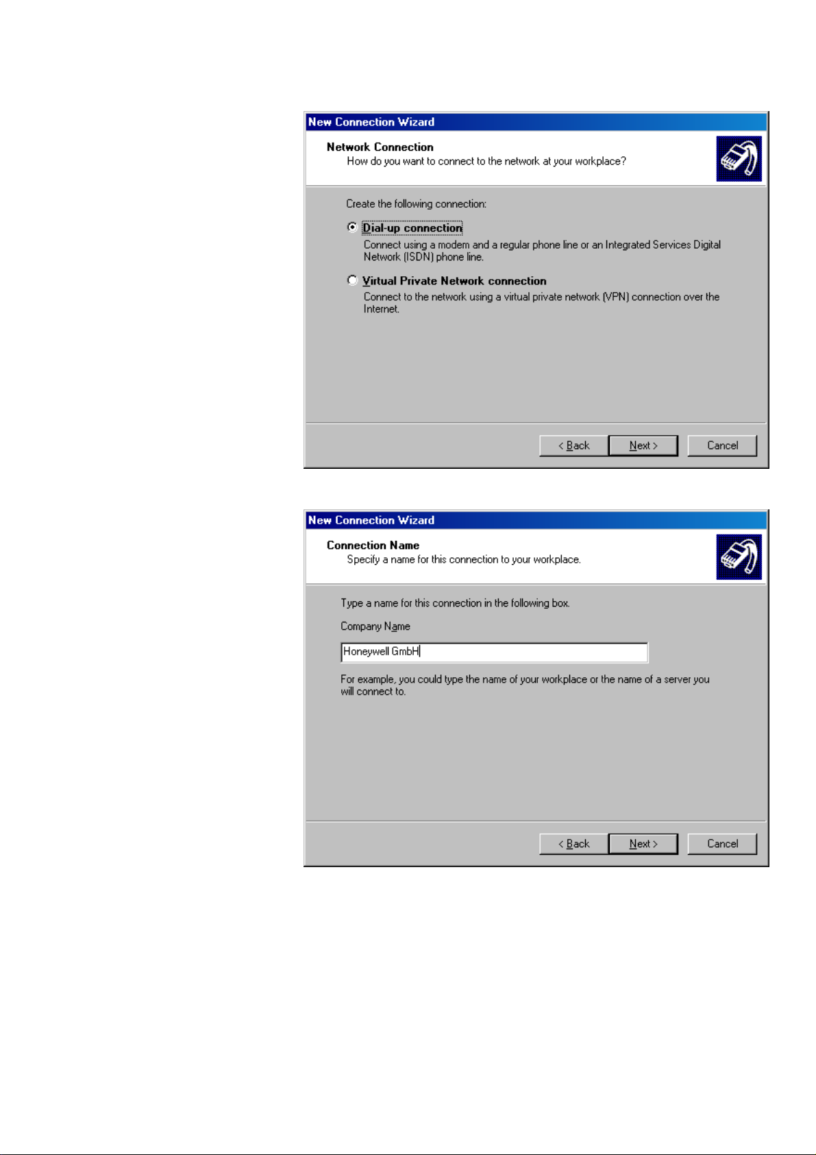
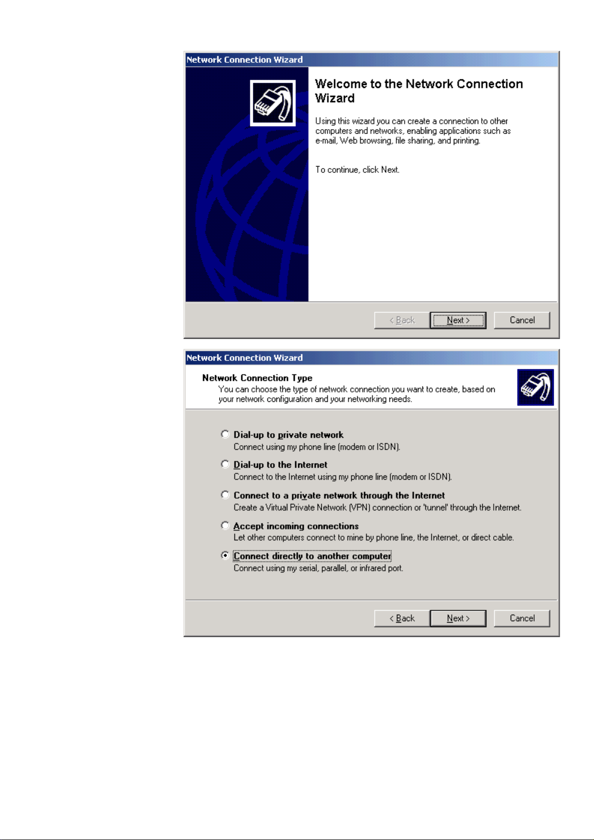
Procedure 1. From the Windows Start menu, select Settings, then Network Connections and
Network Connection Wizard.
RESULT: The New Connection Wizard displays.
2. In the Network Connection Wizard, click the Next button.
EN2B-0289GE51 R0709 22
Page 23
USER GUIDE EXCEL WEB
3. Select Connect to the network at my workplace, and then click the Next
button.
4. Select Dial-up connection, and then click the Next button.
5. In the Company Name field, enter a name for the modem connection, and then
23 EN2B-0289GE51 R0709
click the Next button.
Page 24

EXCEL WEB USER GUIDE
6. In the Phone number field, enter the phone number of the modem connected
to the Excel Web controller, and then click the Next button.
.
NOTE: For the phone number, please contact the telephone network
administrator.
7. Select the connection availability under Anyone´s use or My use only, and
then click the Next button.
.
EN2B-0289GE51 R0709 24
Page 25

USER GUIDE EXCEL WEB
8. Check Add a shortcut to this connection to my desktop, and then click the
Finish button.
9. In the User name field, enter ´xwadmin` and in the Password field, enter
´remad-1234`.
10. Check Save this user name and passwo rd to the following users, and
select Me only or Anyone who uses this computer.
11. Click the Properties button.
25 EN2B-0289GE51 R0709
Page 26
EXCEL WEB USER GUIDE
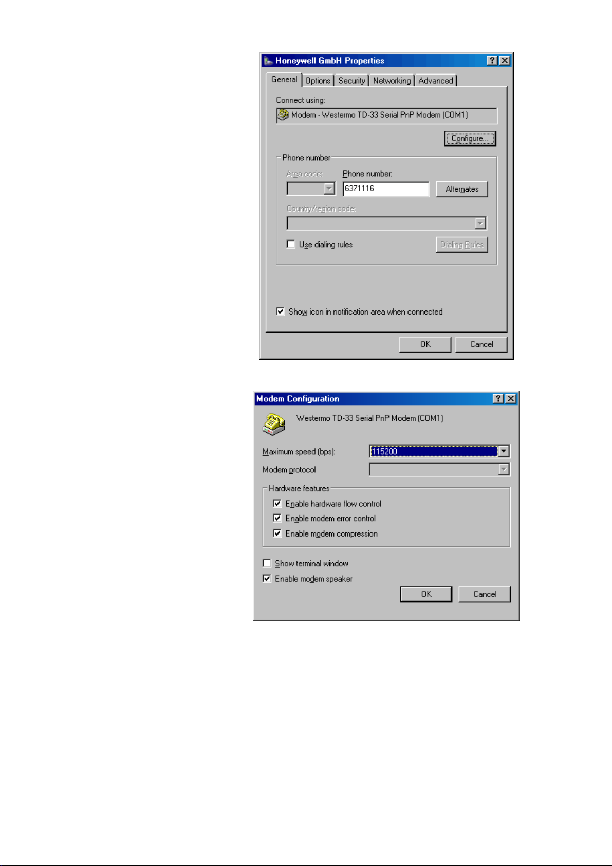
12. On the General tab, click the Configure button.
13. From the Maximum speed (bps) drop-down list box, select ´115200`, and then
click the OK button.
EN2B-0289GE51 R0709 26
Page 27
USER GUIDE EXCEL WEB
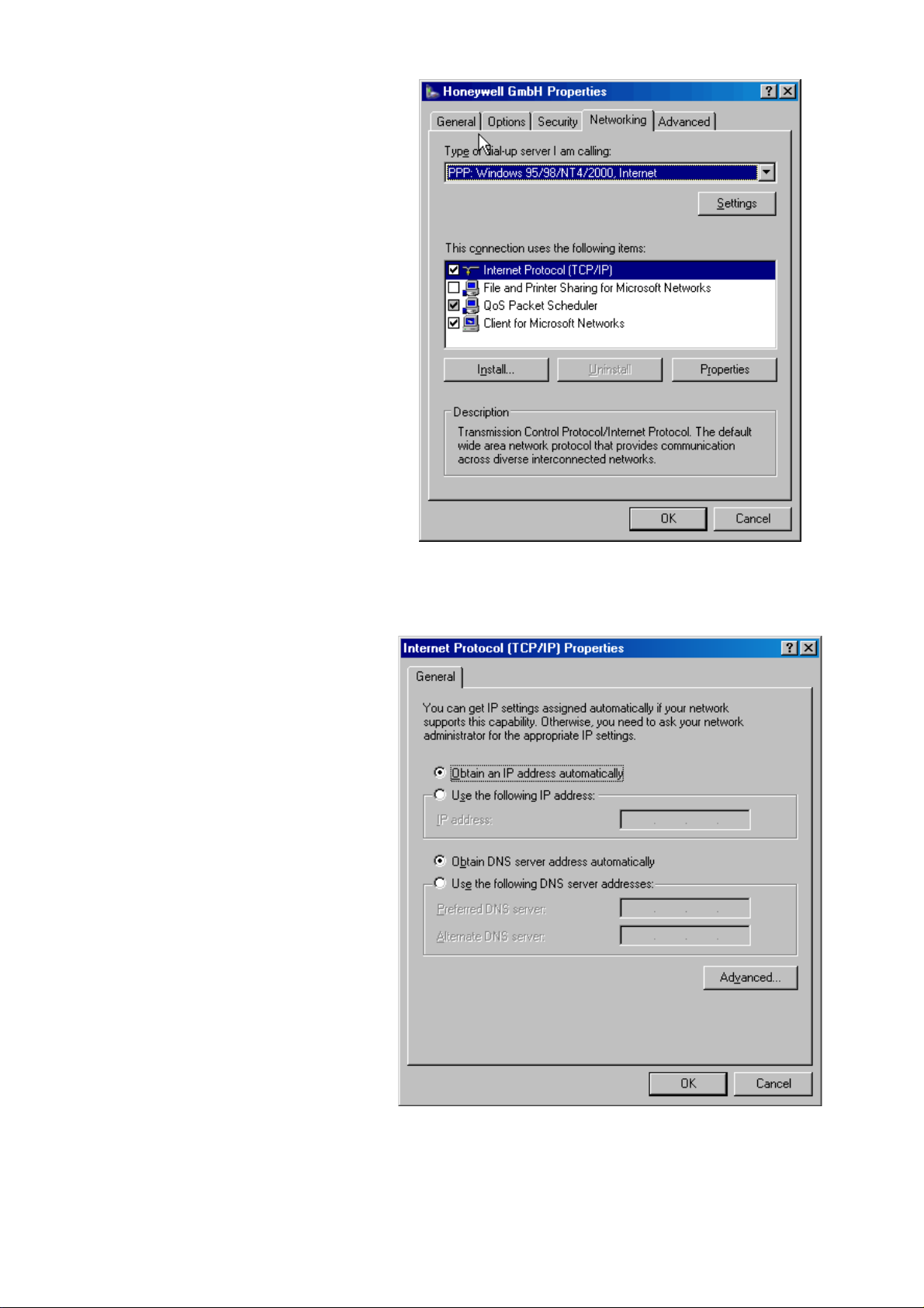
14. Slect the Networking tab.
15. Check and highlight Internet Protocol (TCP/IP) in the list and click the
Properties button.
27 EN2B-0289GE51 R0709
Page 28

EXCEL WEB USER GUIDE
16. On the General tab, select Obtain an IP address automatically, and then click
the OK button.
17. Click the OK button.
RESULT: The Connect… dialog box redisplays.
18. Click the Dial button.
RESULT: You will be connected to the Excel web controller. If
successfully connected, a tooltip in the system tray shows this
with a message.
19. To view connection details, hover over the connection icon in the system tray.
RESULT: A tooltip shows connection details such as connection name,
speed, etc.
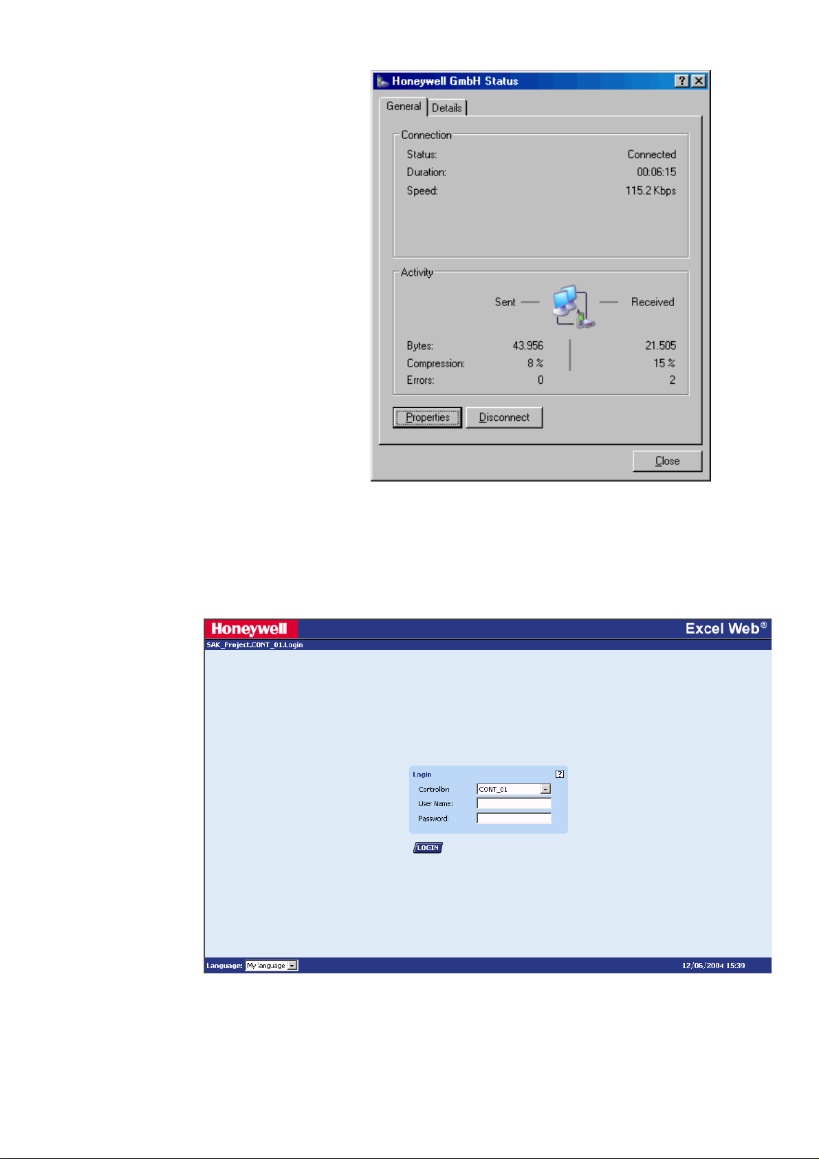
20. Click on the connection icon.
RESULT: The Status dialog box displays showing more details about the
connection.
EN2B-0289GE51 R0709 28
Page 29
USER GUIDE EXCEL WEB
21. Click Close button.
22. To operate the Excel Web controller via HTML Interface, start your web browser
and enter the following IP address:
http://192.168.253.20
RESULT: The Login screen displays (see next page).
For detailed information on the operation of the Excel Web HTML Interface,
please refer to the "Operating the Excel Web HTML Interface" section, p. 117.
29 EN2B-0289GE51 R0709
Page 30
EXCEL WEB USER GUIDE
WEB BROWSER ACCESS VIA SERIAL INTERFACE (RS 232)
The Excel Web controller can be connected to the PC via the RS232 interface.
Connect the free COM port of PC to the port 2 of the Excel web controller by using a
null modem cable.
http://192.168.253.20
Excel Web
IOIO 2
Controller
Fig. 10. Web Browser access via serial interface (RS 232)
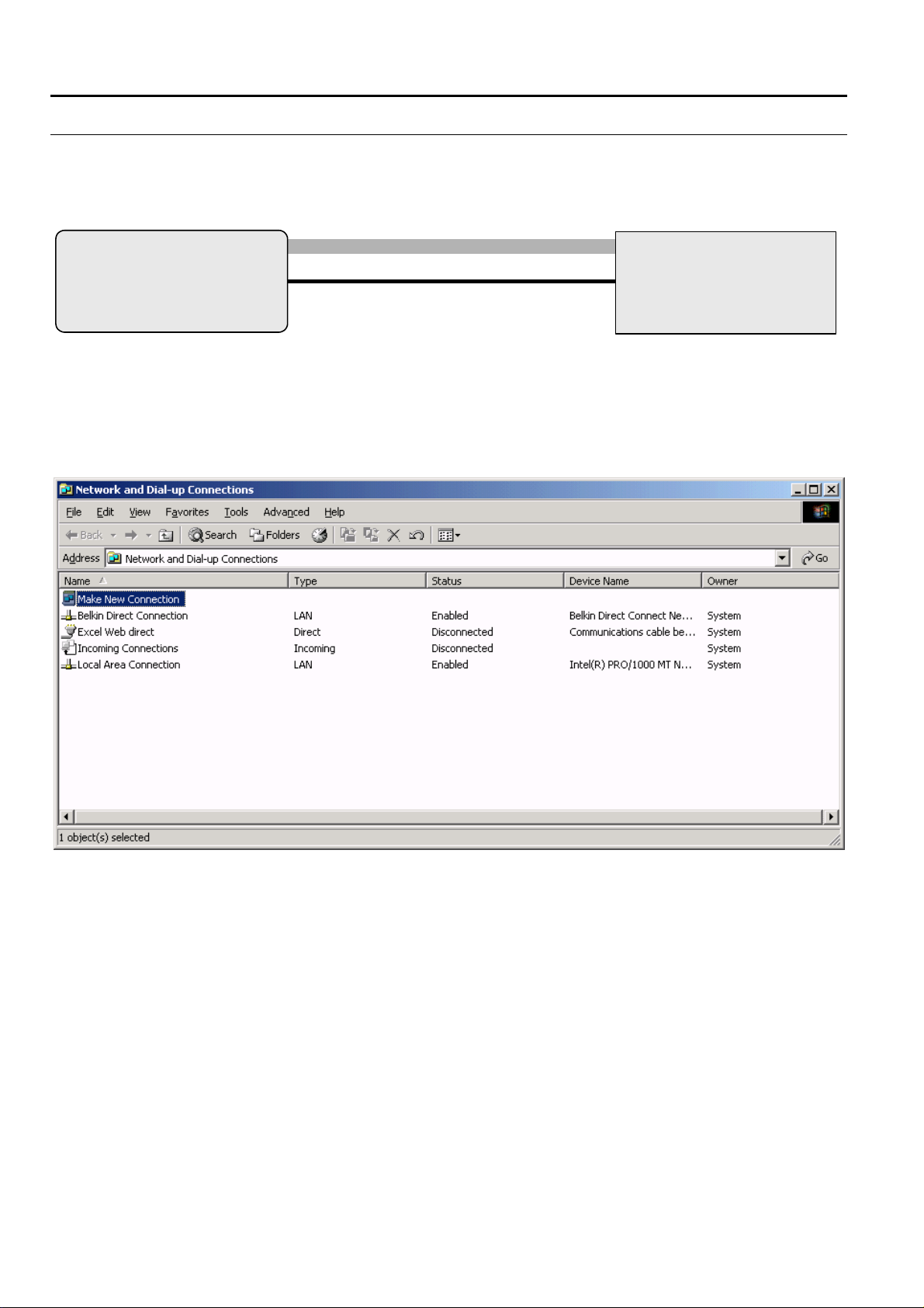
Procedure 1. From the Windows Start menu, select Settings, then Network and Dial-up
Connections.
RESULT: The Network and Dial-Up Connections window displays.
Null Modem Cable
COM
Notebook, Touch panel PC, Desktop
PC
2. Double-click on Make New Connection.
3. In the Network Connection Wizard, click the Next button.
EN2B-0289GE51 R0709 30
Page 31
USER GUIDE EXCEL WEB
4. Select Connect directly to another computer and click the Next button.
31 EN2B-0289GE51 R0709
Page 32

EXCEL WEB USER GUIDE
5. Select the Guest option.
6. Click the Next button.
7. Select the connection availability under For all users or Only for myself.
8. Click the Next button.
EN2B-0289GE51 R0709 32
Page 33

USER GUIDE EXCEL WEB
9. Enter a name for the connection.
10. In the User name and in the Password fields, enter ´xwadmin`, and check the
Save password checkbox.
11. Click the Properties button.
33 EN2B-0289GE51 R0709
Page 34

EXCEL WEB USER GUIDE
12. Select the Networking tab.
13. Check and highlight Internet Protocol (TCP/IP) in the list and click the
Properties button.
EN2B-0289GE51 R0709 34
Page 35

USER GUIDE EXCEL WEB
14. In the Internet Protocol (TCP/IP) Properties dialog box, select Obtain an IP
address automatically and click the OK button.
15. Click the OK button.
RESULT: The Connect… dialog box redisplays.
16. Click the Connect button.
RESULT: You will be connected to the Excel web controller. User name
password, and authentication are verified.
17. If the following message box displays, check the Do not request the failed
protocols next time checkbox and click the Accept button.
18. Check if you have been successfully connected to the Excel Web controller by
clicking on the connection in the Network and Dial-up Connections window.
35 EN2B-0289GE51 R0709
Page 36

EXCEL WEB USER GUIDE
RESULT: If the connection was successfully, the … Status dialog box is
displayed.
If you are not (successfully) connected to the Excel Web
controller, the Connect… dialog box redisplays where you can
connect again.
EN2B-0289GE51 R0709 36
Page 37

USER GUIDE EXCEL WEB
19. To operate the Excel Web controller via HTML Interface, start your web browser
and enter the following IP address:
http://192.168.253.20
RESULT: The Login screen displays.
For detailed information on the operation of the Excel Web HTML Interface,
please refer to the "Operating the Excel Web HTML Interface" section, p. 117.
USER ADMINISTRATION
37 EN2B-0289GE51 R0709
Page 38

EXCEL WEB USER GUIDE
The user administration (user access manager in CARE) is used for defining user
rights according to the required functions. These definitions are done in CARE firstly
by creating the users and issuing the functions they should have permission for in
the Excel Web HTML Interface. In addition, the user administration (user access
manager) is used for defining the language and decimal places of values the Excel
Web HTML Interface should display. User rights can be changed in the Excel Web
HTML Interface dependent on the predefinitions of the user in CARE.
Access Rights List An access rights list for a complete project will be created by assigning predefined
User Profile For each user within a project, a user profile with the following properties will be
NOTE: All users can operate all controllers of a project.
Changes in the user administration will be automatically synchronized
user levels to all executable functions (access rights) of the Excel Web HTML
Interface. An access rights list may look as follows:
Access Right User Level
Change Communication Settings System Admin
Create and Delete Schedules Building Engineer
Create and Delete Trends Building Engineer
Display Diagnostics Tenant
The predefined user levels are arranged hierarchically and the sequence with
descending priority is as follows:
• System Administrator (128)
• Project Administrator (115)
• Building Engineer (96)
• Operator (64)
• Tenant (32)
• Guest (0)
Example:
When assigning ´Operator` to ´Create & Delete Calendars`, a user having a user
(access) level below ´Operator`, for example ´Tenant` or ´Guest`, is not able to
create and delete calendars. A user having a user level equal to or higher than
´Operator`, for example ´Building Engineer` or ´Project Admin` is able to create and
delete calendars.
NOTE: When creating a project in CARE, the System Admin level is
created:
• User name
• User (access) level
• Language
• Decimal places
• Password
• Access rights
• Email address(es)
A user is identified by its user name. One of the predefined user levels will be
appropriately assigned to the user (name).
Due to the access rights list definitions, this assignment automatically determines
the set of access rights, which the user is allowed to execute in the Excel Web
HTML Interface.
All users having a user level higher than or equal to the assigned user level will have
this access right enabled in the Excel Web HTML Interface, all others will not.
among all Excel Web controllers in the same project.
automatically assigned to the user who has created the project.
Only the user who has System Admin user level can create new
users and edit or delete existing users.
EN2B-0289GE51 R0709 38
Page 39

USER GUIDE EXCEL WEB
NOTE: A user can carry out his/her assigned access rights in all controllers of the
In addition, the user profile includes the settings of the language in which the Excel
Web HTML Interface is displayed and the number of decimal places of values to be
displayed in the Excel Web HTML Interface.
For the email alarming function, the user must have an email address assigned
which allows receiving alarm emails generated by the Excel Web controller. For
each user, max. 5 email addresses can be assigned .
Finally, a password for each user must be issued for secure operation of the Excel
Web HTML Interface.
project.
USER PROFILE
PASSWORD
**********
USER NAME
John Q. Public
etc.
LANGUAGE
English (U.S.)
Email Address
JohnQ.Public@yahoo.com
„second email address
„max. 5 email addresses“
ACCESS LEVEL ACCESS RIGHTS (FUNCTIONS)
SystemAdmin
Building Engineer
Tenant
etc.
etc.
DECIMAL
PLACES
2
3
etc.
Create and Delete Calendars
Create and Delete Trends
Display Diagnostics
etc.
Fig. 11. User Profile Creation
Implications of CARE Settings For some items such as datapoints and control loops, access rights can be
predefined in CARE only. Dependent on the settings done in CARE, some items
may not be visible in the Excel Web HTML Interface.
Example:
When assigning the read access level ´building engineer` to all analog
inputs, no analog inputs are visible for users having a user access level
assigned which is lower than the ´building engineer` level, e.g. for users
with the user access levels ´operator`, ´tenant`, or ´guest`.
39 EN2B-0289GE51 R0709
Page 40

EXCEL WEB USER GUIDE
DATAPOINTS
An Excel Web® controller supports up to 600 physical datapoints and an unlimited
number of value datapoints.
A datapoint has different properties according to its type. Properties are displayed
and can be modified via a standard browser on operator interfaces such as laptops,
desktop PCs, or panel PCs. Properties contain information about the given
datapoint. Among many more, this information could be:
• Present value
• Transition events
• Descriptions
• Input limits values
• Operating status
• Elapsed run time
The following sections provide more-detailed information about the different kinds of
datapoints and datapoint properties and explain which properties are assigned to
which datapoints.
In addition, the Excel Web controller has two Integrated I/Os:
Binary Output
• potential-free relay, SPST (single pole single throw), normally open, 24 Vac +/20%, max. 2 A permanent load
• application-driven
• 1 "active" LED, illuminated when contacts closed
The binary output can be used for connecting an alarm buzzer.
Binary Input
• potential-free contact, max. 36 Vdc
• application-driven
• 1 "active" LED, illuminated when contact closed
Physical Datapoints
Physical datapoints are inputs and outputs attached to hardware devices like
sensors and actuators.
The following are examples of physical datapoints:
Analog Inputs NTC, PT 1000, PT 3000, BALCO Sensors (PT 3000/BALCO), standard 0...10 V / 0
Analog Outputs Outputs with a continuous 0...10 V output signal for controlling continuous actuators
Binary Inputs Inputs for processing voltage-free signals (switches, contacts, counters).
Binary Outputs Outputs for driving three-position actuators, for example, a damper motor; two
Multi-State Inputs Inputs used for equipment feedback (Automatic, On, Off)
Multi-State Outputs Outputs controlling multi-stage fans (0, 1, 2, 3)
Pulse Converter Digital inputs for processing pulsed signals up to 20 Hz (depending on I/O module
(4)...20 mA input, to connect outside air temperature sensors, for example.
position devices, for example, a circulation pump; and pulsed outputs
specifications), for example, metered energy consumption.
EN2B-0289GE51 R0709 40
Page 41

USER GUIDE EXCEL WEB
Value Datapoints
Value datapoints are values (intermediate results and parameters) computed while
the application program is running. In contrast to physical datapoints, value
datapoints are not directly connected to hardware devices.
A typical example of a value datapoint is a room temperature setpoint.
Access via datapoint name During system operation, you may need to access these values. To simplify this
Analog Value Datapoints Analog value points are software points containing an analog value in the user
Binary Value Datapoints Binary value points are software points containing a binary value in the user
Multi-state Value Point Multi-state Value datapoints allow switching 32 stages (including the “off stage“) of
A typical example would be a multi-state electric heater or a multi-stage fan.
process, you can include value datapoints in the datapoint list, where you can
access them directly via their datapoint name.
Like physical datapoints, value datapoints, too, can have different properties; for
example, they can specify a manual value, set minimum and maximum values, or
log trends.
The following are types of value datapoints:
• Analog value points
• Binary value points
• Multi-state value points
program.
An analog value point could, for example, contain a flow temperature setpoint calculated from the room setpoint and the outside air temperature via the heating
curve.
program.
For example, logical AND operation:
The AND operation provides a logical 1 output when all input conditions are also
logical 1. Otherwise the output is a logical 0. If the user program contains such an
AND operation on different input conditions, then the output could be available as a
binary value datapoint.
physical digital inputs or outputs. Depending on the number of stages, the multistate value point provides up to 32 editable stage texts, e.g., stage 1, stage 2, stage
3, etc, to be edited in CARE.
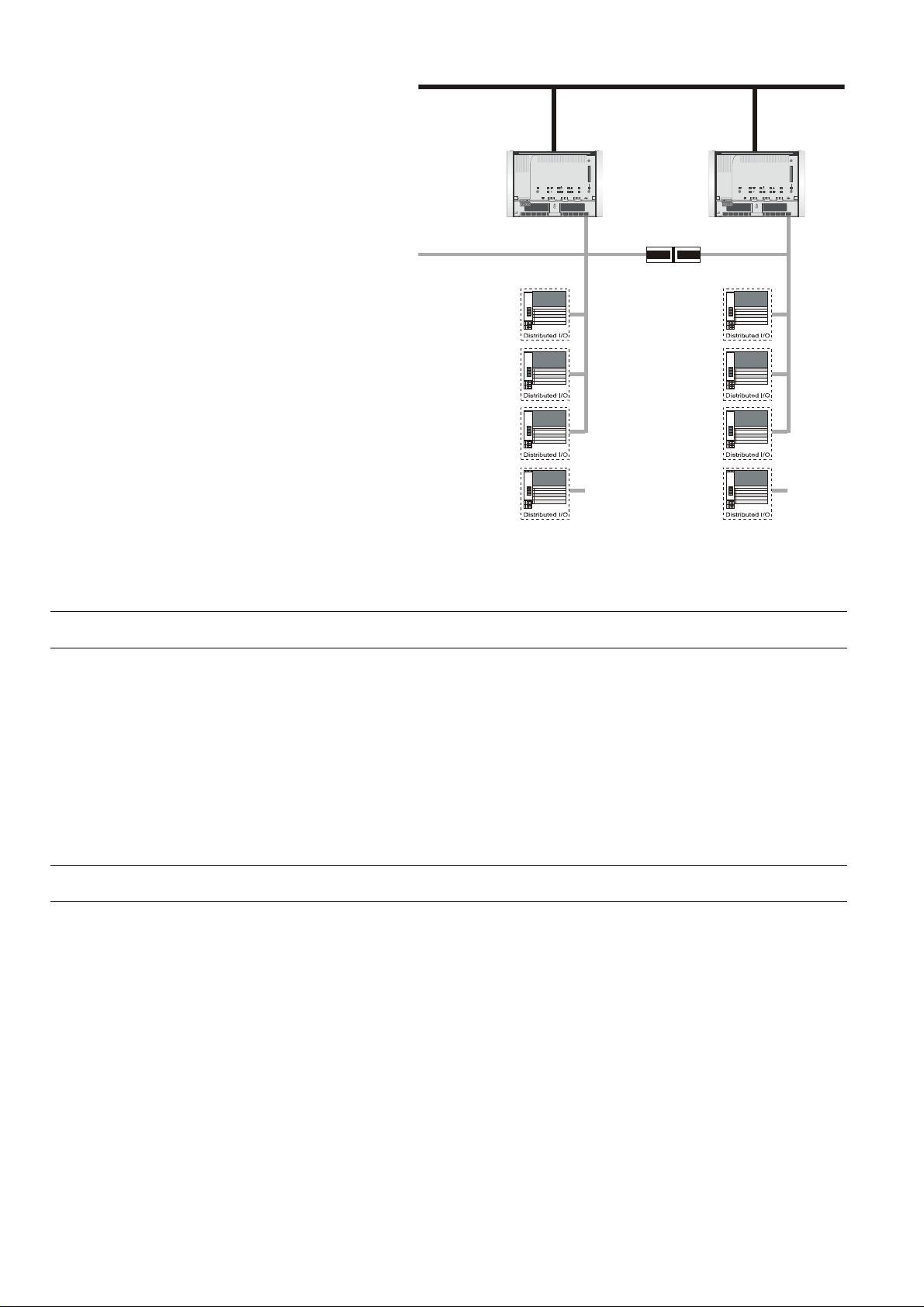
Reference Datapoints
If your control and monitoring system contains more than one controller, the controllers communicate with one another via the BACnet bus. This enables one controller both to read and set the datapoints from other controllers, and to read values
rd
of 3
-party BACnet devices of the project and external BACnet devices which are
not in the project.
This data communication is realized via so-called reference input/output points.
They always originate in or write to another plant and may originate in or write to
another controller.
41 EN2B-0289GE51 R0709
Page 42
EXCEL WEB USER GUIDE
BACnet bus
LON
LON
LON
Excel Web Controller Excel Web Controller
CF
321
LON
CF
321
LonWorks
Router
Fig. 12. Data exchange via reference datapoints on the BACnet bus
Please refer also the datapoint property description in the "Reference" section.
Mapped Datapoints
The Excel Web controller may have I/O devices connected via the LONWORKS
network. L
variables) can be mapped to the property "Value" of physical datapoints (AI, BI, AO,
BO, MI, MO). Analog value, binary value, and multi-state value points are also
supported for NV mapping. Note that multi-state points on BACnet start counting
from 1 while enumerated NVs start counting from zero. So a +1 conversion table
must be applied for NVI mapping and a -1 conversion table must be applied for NVO
mapping.
For more information on L
please refer to the CARE User Guide, EN2B-0182GE51.
ONWORKS network variables (or individual fields of structured network
ONWORKS network variables and datapoint mapping,
Datapoint Properties
Each datapoint type has associated with it various parameters, which allow the user
to set, e.g., the datapoint name, the level of access protection, alarm behavior, and
other options. These parameters are called properties. Each property performs a
specific function related to the datapoint.
Not all properties are available for every datapoint type.
Datapoint Refreshing The following properties will be simultaneously refreshed to an EBI central or the
EN2B-0289GE51 R0709 42
Excel Web HTML Interface:
• Present value
• Operating mode
• Reliability
• Status flags
• Event state
Page 43

USER GUIDE EXCEL WEB
• Event time stamp
• Acknowledged transition
• Command priorities
• Active/Inactive texts
• Elapsed active time
• Time of active time reset
• State texts
• Feedback value
• Time of present value reset
NOTE: A complete list of all properties associated with the various datapoint
Operating Mode The user is able to switch each datapoint between manual and automatic operation.
Automatic
Under automatic operation, the controller processes the values at the inputs, for
instance from temperature sensors. For outputs, under automatic operation, the
status shown by the user/time switch program is adopted, e.g., ´Heating circuit
pump off`.
Manual
During manual operation, the controller uses the manual values, for example, ´flow
temperature setpoint = 60°C`. Outputs adopt the preselected condition, for example,
´Heating circuit pump on`.
Local Manual Override If manual override controls are present on either the analog output or digital output
modules connected via a L
(automatic/manual override) is displayed in the Excel Web HTML Interface.
types can be found in the section Datapoint Properties Overview.
ONWORKS network, then the status of these controls
Properties Descriptions
How to Read the Datapoint Properties Description
In the following, all datapoint properties which exist in the Excel Web HTML
Interface and in CARE are described. Each property description starts with a table
that explains:
• which datapoints the property applies to
• where the property is available, either in CARE or in the HTML Interface or in
both of them
• if the property is editable and where (HTML Interface and/or CARE) it can be
changed.
• the corresponding equivalent name, if the property name is different in the HTML
Interface and in CARE
All valid items are highlighted in gray. Non-valid items remain in white.
Examples:
Datapoint Type AI AO AV
User Interface HTML Interface CARE
Editing - X
Equivalent Auto, Manual
The following table explains the Ackn. (Acknowledged
The following table explains the Active / Inactive Text property.
In this case the property applies to the BI, BO and BV datapoint
types. It is available in the HTML Interface and in CARE. It can
be edited in CARE but not in the HTML Interface. In the HTML
Interface the property is not called Active / Inactive Text but is
displayed as Auto or Manual property.
BI BO BV MI MO MV PC RI RO
Transitions) property. In this case the property applies to all
datapoints except the RI (reference input). It is available in the
43 EN2B-0289GE51 R0709
Page 44

EXCEL WEB USER GUIDE
HTML interface only. It cannot be edited at all and there is no
equivalent.
Datapoint Type
User Interface HTML Interface CARE
Editing
Equivalent
In some exceptions, remarks in quotation marks are added. In
the following table of the Engineering Unit property description,
"assigned to value" means that the engineering unit is not
available as property but is assigned to the current value of the
datapoint.
Datapoint Type
User Interface HTML Interface CARE
Editing "assigned to value" X
Equivalent
AI AO AV BI BO BV MI MO MV PC RI RO
AI AO AV BI BO BV MI MO MV PC RI RO
Ackn. (Acknowledged Transitions)
Datapoint Type AI AO AV BI BO BV MI MO MV PC RI RO
User Interface HTML Interface CARE
Editing
Equivalent
Shows whether a transition has been acknowledged or not. By default, each
transition will be acknowledged by the Excel Web controller and the Ackn. Property
is checked in the Excel Web HTML Interface. On the EBI central, transitions can be
set to be asked for acknowledgement by the operator manually.
Active / Inactive Text
Datapoint Type AI AO AV BI BO BV MI MO MV PC RI RO
User Interface HTML Interface CARE
Editing - X
Equivalent Auto, Manual
To binary points, texts can be assigned in CARE to display the corresponding active
or inactive state of the point in the Excel Web HTML Interface. The texts include
active/inactive (passive) descriptions with unit, and number of states.
Example:
The actual state is displayed as present value in the Excel Web HTML Interface.
See also "Auto" and "Manual" sections.
Active / Inactive text assigned to binary output for switching a pump.
Unit Nu mber of states State (0) State (1)
1 2 OFF ON
2 2 Stopped Running
EN2B-0289GE51 R0709 44
Page 45

USER GUIDE EXCEL WEB
Alarm Delay
Datapoint Type AI AO AV BI BO BV MI MO MV PC RI RO
User Interface HTML Interface CARE
Editing x X
Equivalent
The alarm delay determines how long a ´To-Off-Normal` or a ´To-Normal` transition
must exist before an alarm is generated. Entering an alarm delay time of 10 seconds
means that the limit value must be exceeded for at least 10 seconds before this
datapoint generates an alarm. If the limit value only lasts for 7 seconds, then no
alarm occurs. The alarm handling for a datapoint can be completely disabled by
setting the alarm delay time to a value of 100000 or higher.
Alarm Text
Datapoint Type AI AO AV BI BO BV MI MO MV PC RI RO
User Interface HTML Interface CARE
Editing - X
Equivalent
For the property ´Alarm text`, CARE allows entering personalized alarm texts for the
different event states of an analog or digital point. The assigned alarm text is shown
with the alarm, which is caused by the corresponding transition event.
Alarm texts can have 256 characters at maximum with no restriction on the used
character type.
Analog points have twelve, Digital points have six possible event states. The
following table shows the event states and examples for alarm texts:
Nr. Analog Event States Alarm Text Example Digital Event States Alarm Text Example
1 High Limit to Normal Value below High Limit Fault to Normal Input OK
2 Low Limit to Normal Value above Low Limit Normal to Fault Input Failure
3 Fault to Normal Sensor OK Off-Normal to Normal Input back to Normal
4 Normal to High Limit Value above High Limit Normal to Off-Normal Input Change to Alarm
5 Normal to Low Limit Value below Low Limit Fault to Off-Normal
6 Low Limit to High Limit Off-Normal to Fault
7 High Limit to Low Limit
8 Fault to High Limit
9 Fault to Low Limit
10 Normal to Fault Sensor Break
11 High Limit to Fault Sensor Break
12 Low Limit to Fault Sensor Break
Alarm Type
Datapoint Type AI AO AV BI BO BV MI MO MV PC RI RO
User Interface HTML Interface CARE
Editing - X
Equivalent Notify Type
According to the BACnet Specification, events can be of the type ´alarm` or ´event`.
45 EN2B-0289GE51 R0709
Page 46

EXCEL WEB USER GUIDE
On the EBI, alarms will be graphically indicated by blinking in the status line and
shown in the alarm summary. Events will not be indicated in the status line and will
be shown in the event summary.
The notify type can be defined and changed in CARE. In the Excel Web HTML
Interface, the notify type (alarm type) is displayed only.
For all notification classes, notify type ´Alarm` must be used.
See also "Notify Type" section.
Alarm Value
Please refer to the "Alarm Value Enable" section.
Alarm Value Enable
Datapoint Type AI AO AV BI BO BV MI MO MV PC RI RO
User Interface HTML Interface CARE
Editing x X
Equivalent Alarm Value
Defines the alarm condition of a binary input or value point when an alarm should be
reported in case of binary input changes. The alarm condition can be either the
active state or the inactive state of the point e.g. 0 or 1, ON or OFF, Up or Down. If
the present value is equal to this condition for at least the alarm delay time, then an
OFF-Normal event is generated. In addition an alarm delay can be entered.
Auto
Datapoint Type AI AO AV BI BO BV MI MO MV PC RI RO
User Interface HTML Interface CARE
Editing x
Equivalent
Sets the datapoint in automatic (Auto) operation mode. In Auto operation mode, the
datapoint shows the present value processed by the controller (sensor input values,
time program output values).
See also "Active / Inactive Text" section.
BACnet Instance
Datapoint Type AI AO AV BI BO BV MI MO MV PC RI RO
User Interface HTML Interface CARE
Editing -
Equivalent
The BACnet instance number is part of the internal BACnet addressing in every
BACnet system (BACnet communication). The BACnet instance number of
datapoints is not visible in the Excel Web HTML Interface and the user does not
need the BACnet instance number in order to operate the Excel Web controller.
The BACnet instance number of a device object is visible in the Excel Web HTML
Interface.
EN2B-0289GE51 R0709 46
Page 47

USER GUIDE EXCEL WEB
When creating objects in CARE such as datapoints, schedules or calendars, CARE
assigns an instance number to each object. The instance number is unique within
the same object type but the same instance number may also exist in other object
types. The instance number of the device object is unique on the whole BACnet
network.
The following table shows examples of instances, which CARE automatically
assigns to the corresponding BACnet objects while they are created:
Object Type Instance Number
Analog input 1 1
Analog input 2 2
Analog input 3 3
Analog input 4 4
Analog input 5 5
Binary input 1 1
Binary input 2 2
Binary input 3 3
Binary input 4 4
Binary input 5 5
The instance number in combination with the BACnet object type information is one
method in creating and adding a 3
rd
party BACnet device to the BACnet bus (see
also "BACnet Object ID" section).
This information must be provided by or to the project engineer/vendor who is
responsible for the 3
is responsible for integrating the Excel Web controller into a 3
rd
party BACnet device to be added to the CARE project, or who
rd
party BACnet
system.
NOTE: In Europe it is common using the EDE data format for interchanging
information between BACnet objects. For further information, please
access the BACnet Interest Group Europe e.V. at:
http://www.big-eu.org
BACnet Object (Type)
Datapoint Type AI AO AV BI BO BV MI MO MV PC RI RO
User Interface HTML Interface CARE
Editing -
Equivalent
The BACnet object type is part of the internal BACnet addressing in every BACnet
system (BACnet communication). The BACnet object type is not visible in the Excel
Web HTML Interface and the user does not need the BACnet object type in order to
operate the Excel Web controller.
In the BACnet standard, BACnet objects are classified in types.
Example:
Analog inputs are of BACnet object type "analog input(0)", binary inputs
are of BACnet object type "binary input(3)", devices such as the Excel
web controller and 3
rd
party BACnet devices are of BACnet object type
"device(8)”
The BACnet object type information in combination with the instance number is one
method in creating and adding a 3rd party BACnet device to the BACnet bus (see
also "BACnet Object ID" section).
47 EN2B-0289GE51 R0709
 Loading...