

Page 1
Excel Smart I/O Compact
HONEYWELL EXCEL 5000 OPEN SYSTEM
INSTALLATION INSTRUCTIONS
GENERAL INFORMATION
LonWorks
service LED
LonWorks
service
button
LON 1
removable LonWorks
terminal plug
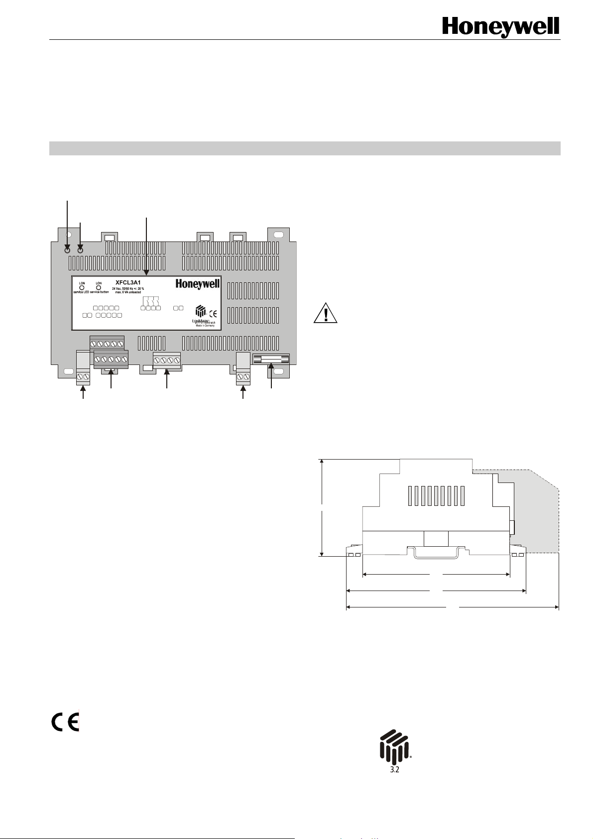
Fig. 1. Top view (optional terminal cover removed)
The Excel Smart I/O Compact is equipped with:
• three relays,
• three digital inputs, and
• three analog inputs, which may be used as slow digital
inputs or as NTC20k temperature sensor inputs.
See also Table 1 on page 2 for a complete overview of
terminals and their functions.
The two models of the Excel Smart I/O differ only in their
power supply:
• XFCL2A1: 230 Vac power supply
• XFCL3A1: 24 Vac power supply
GND9GND
DI 2
8
10
3214 5 6
AI 1
DI 1
LON 2
input terminals
terminal assignment label
DI 3
AI 3
12 15
11
AI 2
GND
7
GND
16
R123 COM
relay output terminals
Rel 1 NO17Rel 2 NO18Rel 3 NO
0441
26
25
24V 0
24V ~
fuse
removable power
supply terminal plug
BEFORE INSTALLATION
IMPORTANT
It is recommended that the controller be kept at room
temperature for at least 24 hours before applying
power; this is to allow the evaporation of any
condensation resulting from low shipping / storage
temperatures.
US requirement, only: This device must be installed
in a UL-listed enclosure offering adequate space to
maintain the segregation of line voltage field wiring
and Class 2 field wiring.
CAUTION
To avoid electrical shock or equipment damage, you
must switch OFF the power supply before attaching /
removing connections to/from any terminals.
MOUNTING
Both models have the same dimensions (W x L x H =
110 x 180 x 60 mm) (see Fig. 2) and conform to IP20 (without
optional terminal protection cover) or IP30 (with optional
terminal protection cover; width is then 130 mm).
59.5
90
110
130
Fig. 2. Excel Smart I/O Compact dimensions (in mm)
The Excel Smart I/O Compact is suitable for mounting on a
standard rail (DIN EN 50022-35 x 7,5), on walls/ceilings, as
well as for installation in wiring cabinets or fuse boxes.
terminal protection
cover (optional)
® U.S. Registered Trademark
Copyright © 2005 Honeywell Inc. EN1B-0282GE51 R0305B
All Rights Reserved
Page 2
EXCEL SMART I/O COMPACT
DIN Rail Mounting/Dismounting
screwing nose
(oval hole)
screwing nose
(oval hole)
eyelet for
cable binder
eyelets for
cable binders
stirrup; pull to
dismount from rail
cable binders
eyelets for
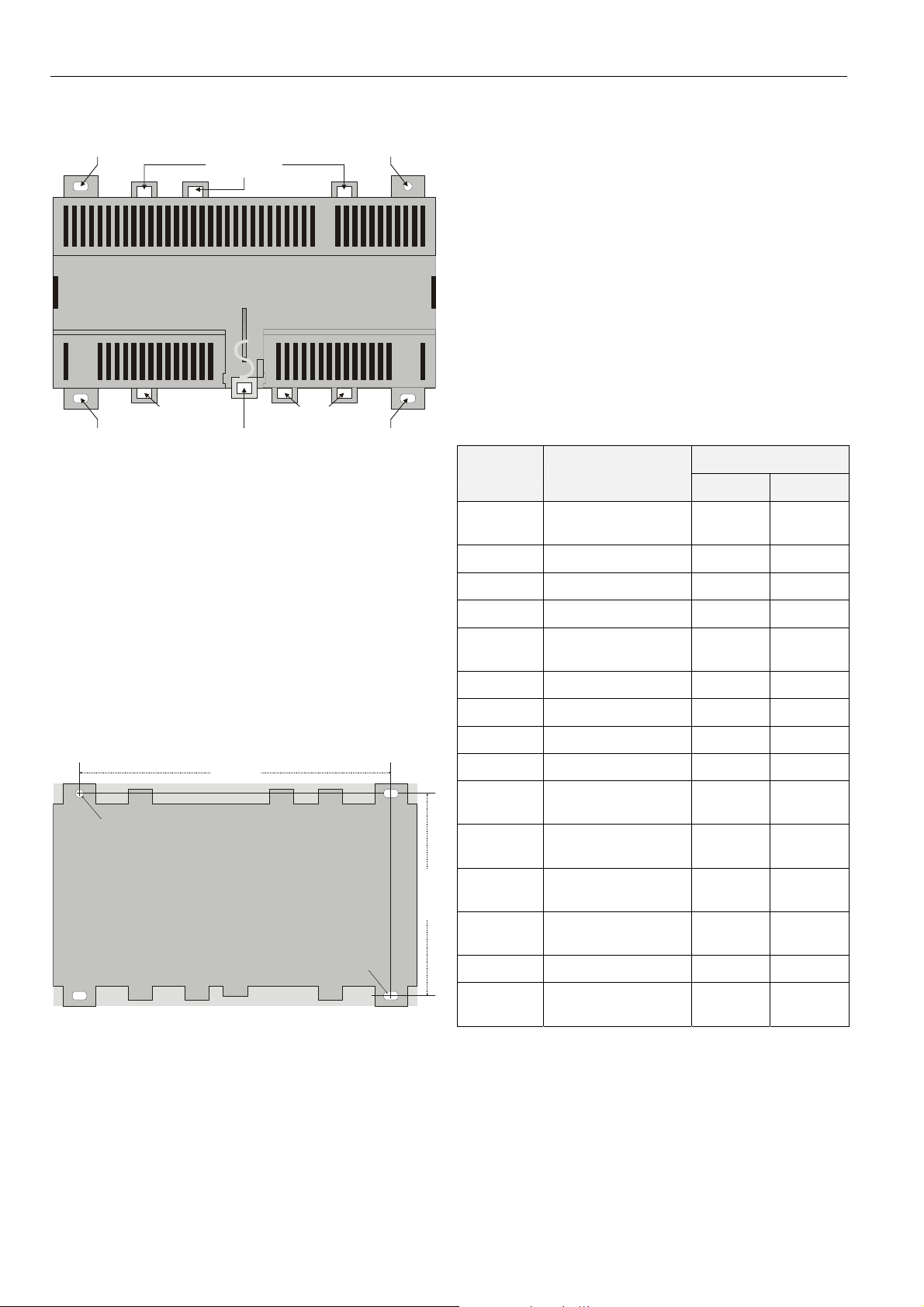
Fig. 3. Housing base (view from below)
The Excel Smart I/O Compact can be mounted onto the DIN
rail simply by snapping it into place. It is dismounted by gently
pulling the stirrup located in the base of the housing (see Fig.
3). When mounted on a DIN rail, the unit must be secured in
place with a stopper to prevent sliding.
screwing nose
(round hole)
screwing nose
(oval hole)
Wall/Ceiling Mounting/Dismounting
The Excel Smart I/O Compact can be mounted on walls or
ceilings in any desired orientation. In the case of ceiling
mounting, however, it should not be operated at ambient
temperatures exceeding 50 °C. The unit is mounted by
inserting 3.5-mm dowel screws through the corresponding
screwing noses.
154 mm
round hole
(diameter: 4 mm)
protection cover's cut-out tabs and snap it (by hand) into
place on the housing. To remove the cover, place a
screwdriver in the leverage slot and pry it loose.
Terminal Assignment
The Excel Smart I/O Compact features two rows of terminal
blocks located on one side for the connection of cables to the
inputs and relay outputs as well as for connecting the removable power supply terminal plug and removable
L
ONWORKS terminal plug.
NOTE: All relay and power supply terminal blocks are
orange-colored.
NOTE: According to VDE guidelines, it is not allowed to mix
low-voltage and high-voltage signals on the relays.
The Excel Smart I/O Compact is equipped with an adhesive
terminal assignment label on the top of the housing (see Fig.
1 on page 1).
Table 1. Overview of terminals and functions
model
terminal # function
XFCL2A1 XFCL3A1
1+2
removable L
connection plug
ONWORKS
X X
3 digital input #1 X X
4 analog input #1 X X
5 analog input #2 X X
6, 7, 8, 9
GND terminals
serving all signals
X X
10 digital input #2 X X
11 digital input #3 X X
12 analog input #3 X X
13+14 not used
15
16
relay common for
relays 1, 2, and 3
relay #1, normallyopen contact
X X
X X
100 mm
oval hole
(4x7 mm)
Fig. 4. Drilling template (view from above)
When equipped with the optional terminal protection cover
(see section "Terminal Protection Cover" on page 6), the
Excel Smart I/O Compact conforms to IP30.
After mounting the Excel Smart I/O Compact onto the wall or
ceiling, provide for cable access by snipping out the terminal
EN1B-0282GE51 R0305B
17
18
relay #2, normallyopen contact
relay #3, normallyopen contact
X X
X X
19 – 24 not used
25+26
removable power
supply plug
230 Vac 24 Vac
See also section “Configuring the Inputs and Outputs” on
page 4.
2
Page 3

EXCEL SMART I/O COMPACT
(
)
Power Supply
General Information
NOTE: All wiring must comply with applicable electrical
codes and ordinances. Refer to job or manufacturers’ drawings for details. Local wiring guidelines (e.g. VDE 0100) may take precedence over
recommendations provided in these installation
instructions.
NOTE: To comply with CE requirements, devices having a
voltage of 50...1000 Vac or 75...1500 Vdc but
lacking a supply cord, plug, or other means for
disconnecting from the power supply must have the
means of disconnection incorporated in the fixed
wiring. This means of disconnection must have a
contact separation of at least 3 mm at all poles.
Use a minimum of 18 AWG (1.0 mm
14 AWG (2.5 mm
2
) for all power wiring.
Power is supplied via a removable terminal plug (attached to
terminals 25 and 26) permitting individual Excel Smart I/O
Compacts to be disconnected from the power supply without
disturbing the operation of other devices powered by the
same source. See Fig. 5.
Excel Smart I/O Compact
XFCL2A1
230
230
Vac
device 3 device 2
device 1
230 Vac (15% / +10%)
Vac
25 26
230
230
Vac
Vac
25 26
230
230
Vac
Vac
25 26
NL
50 / 60 Hz
Fig. 5. Connection to power supply
NOTE: Do not reverse the polarity of the power connection
cables, and avoid ground loops (i.e. avoid connecting one field device to several controllers) as this
may result in short circuits damaging your device.
XFCL2A1 with 230 Vac Power Supply
The XFCL2A1 with 230 Vac power supply is equipped with a
built-in 24 Vac transformer.
Power supply: 230 Vac [-15% / +10%], 50/60 Hz).
Power consumption: < 6 VA (device unloaded)
2
) and a maximum of
Excel Smart I/O Compact
XFCL3A1
24
Vac24Vac
25 26
24
device 1device 2
Vac24Vac
25 26
24 Vac
+/-20%
NL
230 Vac (15% / +10%)
50 / 60 Hz
XFCL3A1 with 24 Vac Power Supply
Power supply: 24 Vac [±20%], 50 or 60 Hz, connected.
Power consumption: < 3 VA (device unloaded)
LonWorks Communications
General Information
The Excel Smart I/O Compact is equipped with a freetopology transceiver for communication on L
networks. The L
ONWORKS network is insensitive to polarity,
eliminating the possibility of installation errors due to
miswiring.
Different network configurations (daisy-chain, loop, and star
configurations, or any combination thereof) are possible (see
also Excel 50/500 L
ONWORKS Mechanisms Interface
Description, EN0B-0270GE51).
Connecting to the LONWORKS Network
IMPORTANT
Do not bundle wires carrying field device signals or
LONWORKS communications together with highvoltage power supply or relay cables. Specifically,
maintain a min. separation of 3 inches (76 mm)
between such cables. Local wiring codes may take
precedence over this recommendation.
IMPORTANT
Try to avoid installing in areas of high electromagnetic noise (EMI).
The unit must be wired to the L
IV 22 AWG (Belden part number 9D220150) or plenum-rated
level IV 22 AWG (Belden part number 9H2201504) nonshielded, twisted-pair, solid-conductor wire. When possible,
use Honeywell 111AK3781, AK3782, AK3791, or AK3792
cable (US part numbers). See Excel 50/5000 L
Mechanisms, EN0B-0270GE51, for details, including
maximum lengths.
Use wire with a minimum size of 20 AWG (0.5 mm
maximum size of 14 AWG (2.5 mm
D-71101 Schönaich
Excel Smart
I/O Compact
1 2 1 2
Made in Germany
Fig. 6. Connection to LonWorks network and termination
module (here: daisy-chain network configuration)
The Excel Smart I/O Compact is connected to the L
network via a removable terminal plug (attached to terminals
1 and 2) permitting individual Excel Smart I/O Compacts to be
connected / disconnected from the L
without disturbing the operation of other devices.
ONWORKS network using level
2
).
Excel Smart
I/O Compact
ONWORKS network
ONWORKS®
D-71101 Schönaich
Made in Germany
ONWORKS
2
) and a
ONWORKS
termination
module
EN1B-0282GE51 R0305B
3
Page 4

EXCEL SMART I/O COMPACT
Depending upon the chosen network configuration, one or two
terminations (see section "L
ONWORKS Termination" on page
6) may be required.
Inputs/Outputs
Wiring the Inputs/Outputs
Use a minimum size of 20 AWG (0.5 mm2) and a maximum of
14 AWG (2.5 mm
maximum length of all input/output cables is 400 m.
Two wires with a total thickness of 14 AWG can be twisted
together and connected using a wire nut (include a pigtail with
this wire group and attach the pigtail to the individual terminal
block). Deviations from this rule can result in improper
electrical contact. Local wiring codes may take precedence
over this recommendation.
power--power
Rel 3
0
ON
1826 25
Configuring the Inputs and Outputs
You can configure the Excel Smart I/O Compact’s inputs and
outputs using Honeywell's LNS plug-in or CARE.
NOTE: The switching logic functionality can be configured
using CARE, only. The LNS plug-in does not support
the switching logic functionality.
Digital Inputs
The Excel Smart I/O Compact is equipped with three digital
inputs suitable for use as fast digital inputs (static digital
inputs or push-buttons for flip-flop) or as totalizer inputs
(square waves).
software detects
inputs as
closed < 400 Ω < 0.8 Vdc max. 2.5 mA
open > 1.5 kΩ > 2.0 Vdc 0…1.5 mA
Totalizer input:
• digital input #1: up to 20 Hz; reacts on falling edge;
• digital input #2: up to 5 Hz; configurable (using
Honeywell’s LNS plug-in) to react on rising or falling edge;
• digital input #3: up to 5 Hz; configurable (using
Honeywell’s LNS plug-in) to react on rising or falling edge.
2
) for all input/output connections. The
Excel Smart I/O Compact
R123
Rel 1
Rel 2
COM
ON
ON
15
16
17
COMST1ST2ST3
3-stage fan
Fig. 7. Overview of inputs and outputs
Table 2. Digital input characteristics
AI3 DI3 DI2 GND GND GND GND AI2 AI1 DI 1 LON2 LON1
10 9 8 7 6 5
12 11
1 2
1 2
AI as
NTC20kOhm
DI as
totalizer
N L
resistive input
(dry contact)
AI as slow DI
voltage
input
3
4
2 1
DI
current out
of terminal
Analog Inputs
The Excel Smart I/O Compact is equipped with three analog
inputs. The analog inputs may be used as NTC20k temperature sensor inputs or as slow digital inputs. The analog
inputs do not support 0…10 V input.
Table 3. Slow digital input characteristics
software de-
tects inputs as
resistive input
(dry contact)
high/low
switching at
current out
of terminal
closed < 200 Ω < 1.5 Vdc < 0.3 mA
open > 50 kΩ > 3.5 Vdc < 0.1 mA
Table 4. Accuracy, resolution of inputs (NTC20k sensors)
temperature range accuracy resolution
-50 to -40 °C (-58 to -40 °F)
-40 to -30 °C (-40 to -22 °F)
-30 to -20 °C (-22 to -4 °F)
-20 to -10 °C (-4 to 14 °F)
-10 to 0 °C (14 to 32 °F)
0 to 10 °C (32 to 50 °F)
10 to 50 °C (50 to 122 °F)
50 to 70 °C (122 to 158 °F)
70 to 90 °C (158 to 194 °F)
90 to 100 °C (194 to 212 °F)
100 to 120 °C (212 to 248 °F)
120 to 150 °C (248 to 302 °F)
≤ 4.11 K
≤ 2.12 K
≤ 1.39 K
≤ 0.65 K
≤ 0.42 K
≤ 0.27 K
≤ 0.30 K
≤ 0.45 K
≤ 1.17 K
≤ 1.44 K
≤ 2.29 K
≤ 5.11 K
For all NTC20k sensor inputs, temperatures of ≤ -50 °C are
interpreted as being due to a sensor break, and temperatures
of ≥ +150 °C are interpreted as being due to a sensor shortcircuit.
Relay Outputs
The Excel Smart I/O Compact is equipped with three
normally-open relay outputs.
Current Limitations
NOTE: If inductive components are to be connected to the
relays and if these relays switch more often than
once every two minutes, these components must be
prevented from causing harmful interference to radio
or television reception (conformance with
EN 45014).
• A min. current of 50 mA is required to ensure a reliable
contact.
• The normally-open contacts are designed for a max. continuous current of 3 A at max. 230 Vac and cos φ = 1. The
d.c. characteristic is shown in Fig. 8.
1.42 K
0.77 K
0.44 K
0.27 K
0.17 K
0.12 K
0.11 K
0.19 K
0.35 K
0.48 K
0.92 K
2.3 K
EN1B-0282GE51 R0305B
4
Page 5

EXCEL SMART I/O COMPACT
300
200
100
ohmic load
switching voltage (Vdc)
10
0.1 0.2 0.5 1.0 2.0 5.0 10.0 20.0
switching current (A)
Fig. 8. Relay characteristic
Replacing the Fuse
NOTE: Before replacing the fuse (see also Fig. 1 on page
1), disconnect the Excel Smart I/O Compact from the
power source by detaching the removable terminal
plug attached to terminals 25 and 26.
CAUTION
Depending upon actual wiring, even after you have
switched OFF the power supply, the relays may still be
under high voltage.
Troubleshooting
The Excel Smart I/O Compact features a LONWORKS service
LED and corresponding L
1) for commissioning and troubleshooting.
When the service button is pressed, the service pin message
is broadcast.
See Table 5 for a description of the meaning of the various
different possible behaviors of the L
For more information on standard service LED behavior, refer
to Motorola L
ONWORKS Technology Device Data Manual,
page AL-190.
Possible Problems and Recommended Actions
Check to see if the LONWORKS service LED's behavior is
changed when you switch the power OFF/ON. Please contact
Honeywell if this does not solve the problem.
ONWORKS service button (see Fig.
ONWORKS service LED.
Table 5. L
1
2
3
4
5
6a
6b
6c
6d
7
8
9
ONWORKS Service LED Behaviors and Meanings
LED blinking pattern
LED remains OFF after
power-up.
LED is lit continuously
after first power-up.
LED flashes at power-up,
goes OFF, then is lit continuously.
LED flashes briefly
periodically.
LED repeatedly blinks ON
for 1 s and OFF for 1 s.
OFF duration ≈ 10 s.
Afterwards, the service
LED turns ON and remains ON, indicating
completion of the blanking
process.
OFF duration ≈ 1 s.
Afterwards, the service
LED is lit continuously.
OFF duration is 1...15 s,
depending on application
size and system clock.
Afterwards, service LED
repeatedly blinks ON for
1 s and OFF for 1 s.
OFF duration is indefinite
(1...15 s to load internal
EEPROM; remains OFF).
LED remains OFF after a
short ON duration.
LED flashes for 1 minute
in following pattern: 5x
ON/OFF, 5 sec OFF, 5x
ON/OFF
LED flashes continuously
in following pattern: 4x
ON/OFF followed by 5 sec
pause.
meaning
Defective device hardware. Suspect
power supply problems, clock
problems, or defective Neuron Chip.
Defective hardware.
Controller lacks application.
Controller is probably experiencing
continuous watchdog resets, or
external memory or EEPROM is
corrupt.
Controller is unconfigured but has an
application.
Using EEBLANK on a Neuron 3150
Chip-based custom node.
First power-up with a new PROM on
a Neuron 3150 Chip-based
customized node. Application-less
firmware state exported.
First power-up with a new PROM on
a Neuron 3150 Chip-based
customized node. Unconfigured
firmware state exported.
First power-up with new PROM on
Neuron 3150 Chip-based customized node. Configured firmware
state exported.
Controller is configured and running
normally.
Controller has received WINK
command from network. Other
physical outputs are unaffected.
Neuron communication failure or
sensor break.
EN1B-0282GE51 R0305B
5
Page 6

EXCEL SMART I/O COMPACT
Accessories
Terminal Protection Cover
Required for wall/ceiling mounting. Set of eight covers.
order no.: XAL_COV_L
LONWORKS Termination
One or two LONWORKS terminations are required, depending
on the given LonWorks bus layout. See section "Connecting
to the L
ONWORKS Network" on page 3.
Two different L
LONWORKS termination module, order no.: 209541B
LONWORKS connection / termination module (mountable on
DIN rails and in fuse boxes), order no.: XAL-Term
removable screw-type
3-pole terminal block
ONWORKS termination modules are available:
l
l
e
w
y
e
n
o
H
m
r
e
T
-
L
A
X
4
3
L
L
O
O
N
N
plug-in
jumper
3
4
LON
Termi nat ion
FTT/LPT Bus
FTT/LPT Free
Park Position
5
1
shield shield
06
Fig. 9. L
ONWORKS connection and termination module
Automation and Control Solutions
Honeywell GmbH
Böblinger Straβe 17
D-71101 Schönaich
Phone: (49) 7031 63701
Fax: (49) 7031 637493
http://europe.hbc.honeywell.com
Subject to change without notice. Printed in Germany Manufacturing location certified to
EN1B-0282GE51 R0305B
 Loading...