

Page 1
XFC1Axx, XFC1Dxx, XFC2Axx, XFC2Dxx, XFC3Axx,
HONEYWELL EXCEL 5000 OPEN SYSTEM
GENERAL INFORMATION
In addition to the four fast digital inputs and four relays (two
normally open, two changeover) present in every Excel Smart
I/O, specific models are equipped as follows:
Removable Terminals (XFC1Dxx), 110 Vac (long housing)
• XFC1D06001: four universal inputs (NTC20k), two
0...10 V analog outputs, built-in transformer, six manual
overrides, ten status LEDs
Removable Terminals (XFC2Dxx), 230 Vac (long housing)
• XFC2D05001: two universal inputs (PT1000, Ni1000, or
Ni1000TK5000), two 0...10 V analog outputs, built-in
transformer, six manual overrides, ten status LEDs
• XFC2D06001: four NTC20k universal inputs, two 0...10 V
analog outputs, built-in transformer, six manual overrides,
ten status LEDs
Removable Terminals (XFC3Dxx), 24 Vac (short housing)
• XFC3D04001: two universal inputs for three-wire PT100
sensors, two 0...20 mA analog outputs, six manual
overrides, ten status LEDs
• XFC3D05001: two universal inputs (PT1000, Ni1000, or
Ni1000TK5000), two 0...10 V analog outputs, six manual
overrides, ten status LEDs
• XFC3D06001: four NTC20k universal inputs, two 0...10 V
analog outputs, six manual overrides, ten status LEDs
Fixed Terminals (XFC1Axx), 110 Vac (long housing)
• XFC1A06001: four universal inputs (NTC20k), two
0...10 V analog outputs, built-in transformer
Fixed Terminals (XFC2Axx), 230 Vac (long housing)
• XFC2A05001: two universal inputs (PT1000, Ni1000, or
Ni1000TK5000), two 0...10 V analog outputs, built-in
transformer
• XFC2A06001: four NTC20k universal inputs, two 0...10 V
analog outputs, built-in transformer
Fixed Terminals (XFC3Axx), 24 Vac (short housing)
• XFC3A04001: two universal inputs for three-wire PT100
sensors, two 0...20 mA analog outputs, short housing
• XFC3A05001: two universal inputs (PT1000, Ni1000, or
Ni1000TK5000), two 0...10 V analog outputs
• XFC3A06001: four NTC20k universal inputs, two 0...10 V
analog outputs
The term "universal inputs" refers to analog inputs for temperature-sensor signals which can be configured as voltagevariable or slow digital inputs (e.g. for dry-contact / opencollector signals). In the case of the XFC3A04001 and
XFC3D04001, reconfiguration of the two 3-wire PT100 universal inputs yields four voltage-variable or slow digital inputs.
Further, the universal inputs and the analog outputs each
feature an extra 24 Vac power output terminal capable of
powering field devices.
BEFORE INSTALLATION
IMPORTANT
INSTALLATION
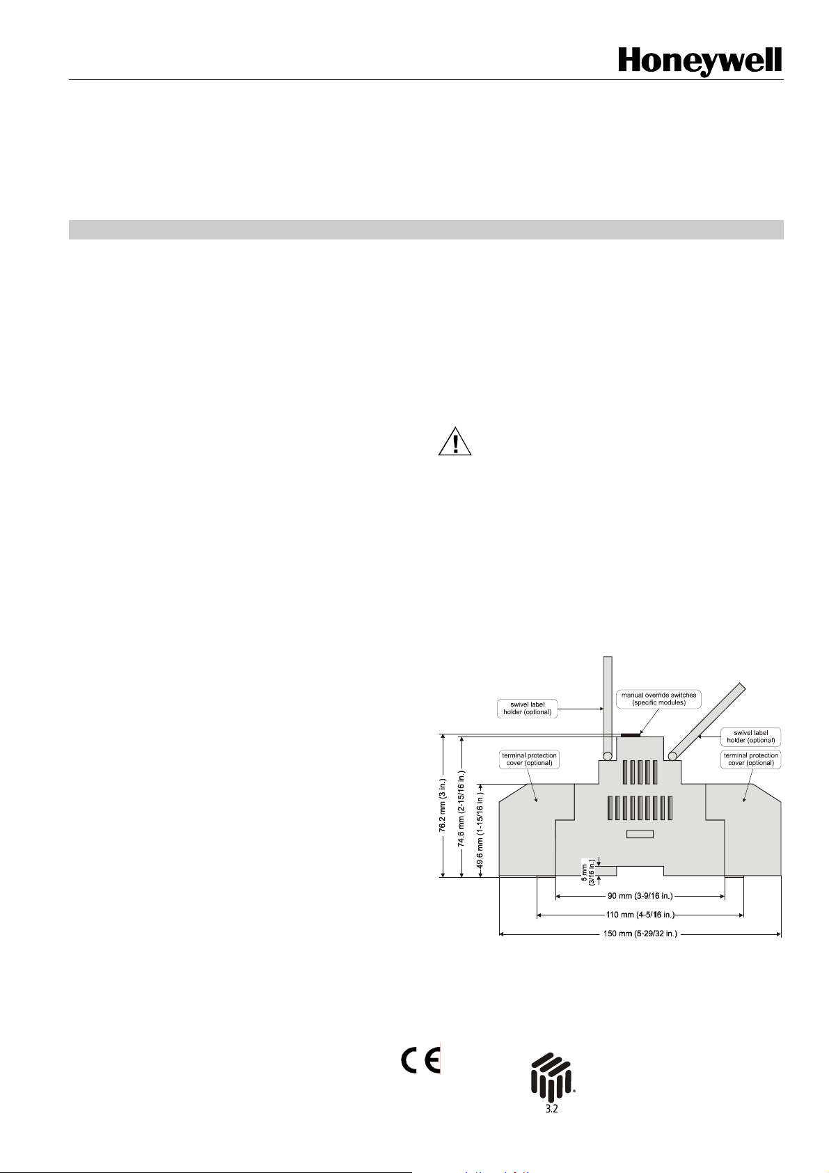
Mounting
The Excel Smart I/O is available with either
• short (W x L x H = 126 x 76 x 110 mm) or
• long (W x L x H = 180 x 76 x 110 mm)
housings (see Fig. 1) conforming to IP20/30. The mounting
procedures are similar for both sizes.
The Excel Smart I/O is suitable for mounting on both a
standard rail (DIN EN 50022-35 x 7,5) for installation in wiring
cabinets or fuse boxes, and on walls/ceilings.
Excel Smart I/O
AND XFC3Dxx MODULES
INSTALLATION INSTRUCTIONS
It is recommended that the Excel Smart I/O be kept at
room temperature for at least 24 h before applying
power to allow the evaporation of any condensation
resulting from low shipping / storage temperatures.
CAUTION
To avoid electrical shock or equipment damage, you
must turn OFF the power supply before attaching /
removing connections to/from any terminals.
Fig. 1. Excel Smart I/O housing (side view)
® U.S. Registered Trademark
Copyright © 2004 Honeywell Inc. EN1B-0180GE51 R1004B / 95-7666-5
All Rights Reserved
Page 2
EXCEL SMART I/O MODULES
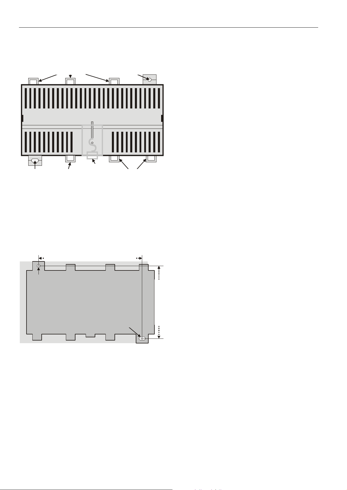
DIN Rail Mounting/Dismounting
The unit can be mounted onto the DIN rail simply by snapping
it into place. It is dismounted by gently pulling the stirrup
located in the base of the housing (see Fig. 2).
screwing nose
(round hole)
eyelets for
cable binders
screwing nose
(oval hole)
eyelets for
cable binders
eyelet for
cable binders
stirrup;
pull to dismount
from rail
Fig. 2. Housing base (view from below)
When mounted on a DIN rail, the unit must be secured in
place with a stopper to prevent sliding.
Wall/Ceiling Mounting/Dismounting
The unit can be mounted on walls or ceilings in any orientation desired. In the case of ceiling mounting, however, it
should not be operated at ambient temperatures exceeding
45 °C. The unit is mounted by inserting 3.5-mm dowel screws
through the corresponding screwing noses.
short housing: 100 mm; long housing: 154 mm
round hole
(diameter: 4 mm)
oval hole
(4x7 mm)
short housing: 100 mm
Fig. 3. Drilling template (view from above)
After mounting the Excel Smart I/O, provide for cable access
by snipping out the terminal protection covers' cut-out tabs
and snap (by hand) the covers (available in packs of 8) into
place onto the housing. To remove a cover, place a screwdriver in the leverage slot (see Fig. 10) and pry it loose.
Power Supply
General Information
All module inputs and outputs are protected against
overvoltages of max. 40 Vdc and 24 Vac.
NOTE: Local wiring guidelines (e.g. VDE 0100) may take
precedence over recommendations provided in
these installation instructions.
NOTE: To comply with CE requirements, devices with a
voltage in the range of 50 to 1000 Vac or 75 to
1500 Vdc lacking a supply cord, a plug, or other
means for disconnection from the power supply
having a contact separation of at least 3 mm at all
poles must have the means for disconnection
incorporated in the fixed wiring.
Models equipped with a built-in transformer are powered with
either:
• 230 Vac (-15%/+10%), 50 or 60 Hz (XFC2xx) or
• 110 Vac (-15%/+10%), 50 or 60 Hz (XFC1xx)
When not supplying external devices with 24 Vac, these
models have a power consumption of under 17.5 VA.
Models with a short housing are powered with 24 Vac (±20%),
50 or 60 Hz from an external transformer (which can power
more than a single Excel Smart I/O; in this case, it is essential
that the different Excel Smart I/O's not be connected with
each other in any additional fashion, e.g. by being grounded,
or by being connected to the same field devices). The 24 V
models have a power consumption of under 6.5 VA.
Each universal input and each analog output features a
24 Vac power output terminal capable of supplying power to
field devices. If the module is supplied with direct current,
these power output terminals will deliver only direct current.
NOTE: The max. combined current draw of all of the field
devices supplied by the power output terminals of a
single Excel Smart I/O equipped with a built-in transformer must not exceed 300 mA (cos φ = 1) for prolonged periods of time. In the case of an Excel
Smart I/O powered by an external transformer, the
max. combined current draw is 500 mA (cos φ = 1).
Disregarding these limits can result in the destruction
of the built-in / external transformer.
Connecting to the Power Supply
The Excel Smart I/O is connected to the power supply as
shown in Fig. 4 or Fig. 5, as the case may be.
All wiring must comply with applicable electrical codes and
ordinances. Refer to job or manufacturers’ drawings for
details. Use a min. of 18 AWG (1.0 mm
long housing: 100 mm
AWG (2.5 mm
2
) for all power wiring.
Do not reverse the polarity of the power connection cables.
Also, avoid ground loops (i.e. do not connect one field device
to several Excel Smart I/O modules): Failure to observe these
instructions may result in short circuits, damaging your
devices.
In the case of models with removable terminals, an orangecolored T terminal plug may be used. In this case, the T
terminal plug is plugged into pins 1 and 2 (24 Vac models) or
pins 43 and 44 (110 Vac and 230 Vac models).
If power is supplied via T terminal plugs, it is possible to
disconnect individual Excel Smart I/O modules from the
power supply without disturbing the operation of other devices
powered by the same source.
2
) and a max. of 14
EN1B-0180GE51 R1004B / 95-7666-5
2
Page 3

A
A
A
A
A
A
A
A
↑
↑
A
A
A
A
A
A
A
A
↑
↑
24V
A
A
A
A
A
A
A
↑
↑
↑
A
A
A
A
A
A
A
↑
↑
↑
24V
0
24 Vac
+/- 20%
230 Vac
120 Vac
~
22
24V
~
1
24V
~
22
24V
~
1 2
23
24V
0
2
24V
0
23
24V
0
fuses dependent
24V
AI1
out
109
24
V
0...10 Vdc
active sensor 1
24V
AI1
out
109
24
V
0...10 Vdc
active sensor 1
upon your
transformer
AI1
0
Y
11
0
↑
AI1
0
Y
11
0
↑
24V
out
12
24
V
0...10 Vdc
24V
out
12
24
V
0...10 Vdc
AI2
0
13
0
AI2
0
13
0
Excel Smart I/O
AI2Y24V
I3
I3
24V
I4
out
18
24
V
0...10 Vdc
I4
0
Y
19
20
0
↑
out
0
Y
16
1514
17
24
0
↑
V
0...10 Vdc
active sensor 3 actuator 1
↑
Excel Smart I/O
AI2Y24V
I3
I3
24V
I4
out
18
24
V
0...10 Vdc
I4
0
Y
19
20
0
↑
out
1514
24
V
0...10 Vdc
active sensor 3
↑
0
Y
16
17
0
↑
24V
out
30
24
V
0...10 V
24V
out
30
24
V
0...10 V
actuator 1
O1
O1
24V
0
31
0
O1
0
31
0
O2
out
0
Y
34
32
33
M
24
0
V
M
0...10 V
actuator 2active sensor 4active sensor 2
O1
24V
O2
out
Y
0
32
33
34
M
24
0
V
M
0...10 V
actuator 2active sensor 4active sensor 2
Fig. 4. Connection to power supply (24 Vac models)
Excel Smart I/O
~
0
24V
power
power
out
43
44
24
V
active sensor 1 active sensor 3 actuator 1
AI1
0
109
0
0...10 Vdc
24V
AI1
AI2
AI2Y24V
AI3
I3
24V
I4
I4
24V
O1
O1
24V
O2
out
Y
0
out
0
Y
out
0
Y
out
0
13
12
11
↑
24
V
0...10 Vdc
16
1514
24
V
0...10 Vdc
0
↑
19
17
18
20
0
24
0
↑
V
0...10 Vdc
30
24
V
0...10 V
Y
31
32
0
M
out
33
24
V
0...10 V
actuator 2active sensor 4active sensor 2
O2
0
Y
34
35
0
M
Excel Smart I/O
~
0
power
power
43
44
N
230 Vac
(110 Vac)
+10%/-15%
24V
out
24
V
active sensor 1 active sensor 3 actuator 1
AI1
0
109
0
0...10 Vdc
24V
AI1
AI2
AI2Y24V
AI3
I3
24V
I4
I4
24V
O1
O1
24V
O2
out
Y
0
out
0
Y
out
0
Y
out
0
12
11
13
1514
16
17
18
19
20
24
↑
24
0
V
0...10 Vdc
0
V
0...10 Vdc
24
↑
V
0...10 Vdc
0
↑
30
24
V
0...10 V
Y
31
32
0
M
out
33
24
V
0...10 V
actuator 2active sensor 4active sensor 2
O2
0
Y
34
35
0
M
Fig. 5. Connection to power supply (110 Vac and 230 Vac
models)
LonWorks Communications
General Information
The Excel Smart I/O is equipped with a free topology transceiver (FTT10A) for communicating on L
works. The L
ONWORKS network is insensitive to polarity,
eliminating installation errors due to miswiring. Different
network configurations (daisy-chain, loop, and star
configurations, or any combination thereof) are possible (see
also: Excel 50/500 L
ONWORKS Mechanisms Interface
Description, EN0B-0270GE51).
Connecting to the LONWORKS Network
IMPORTANT REMARKS:
— Do not bundle wires carrying field device signals or
L
ONWORKS communications together with high-voltage
power supply or relay cables. Specifically, maintain a
min. separation of 3 inches (76 mm) between such
cables. Local wiring codes may take precedence over
this recommendation.
ONWORKS® net-
EXCEL SMART I/O MODULES
— Try to avoid installing in areas of high electromagnetic
noise (EMI).
The unit must be wired to the L
O2
Y
IV 22 AWG (Belden part number 9D220150) or plenum-rated
35
ONWORKS network using level
level IV 22 AWG (Belden part number 9H2201504) nonshielded, twisted-pair, solid-conductor wire. When possible,
use Honeywell AK3781, AK3782, AK3791, or AK3792 cable
(US part numbers). See E-Bus (L
ONWORKS Network) Wiring
Practices, form number 74-2865, for more information,
including max. lengths.
Use wire with a min. size of 20 AWG (0.5 mm
size of 14 AWG (2.5 mm
O2
Y
35
Connection to the L
2
).
ONWORKS network is as shown in Fig. 6
2
) and a max.
and Fig. 7 via terminal pins 3 and 4 (black screw-type T terminal plug) underneath the terminal protection cover (if
present) located on the low-voltage side.
In the case of terminals connected to the L
ONWORKS network
via a removable terminal plug, it is possible to disconnect
individual modules from the network without disturbing the
operation of other devices in the same network.
Depending upon the chosen configuration, one or two termination modules (either part no. 209541B or XAL-Term) may
be required (see also: Excel 10 FTT/LPT 209541B Termination Module Installation Instructions, form 95-7554).
24V
24V
LON
~
22
24V
~
1
24V
~
22
24V
~
1
LON
1
2
0
23
24
25
24V
LON
LON
0
1
2
3
24V
LON
LON
0
1
23
24
24V
LON
LON
0
1
3
2
Excel Smart I/O with fixed terminals
2
4
2
25
Excel Smart I/O with fixed terminals
2
4
Fig. 6. Connection to L
ONWORKS (fixed terminals)
Excel Smart I/O
24V
24V
0
~
1
2
removable
T plug
LON
1
3
LON
2
4
Excel Smart I/O
24V
24V
0
~
1
2
removable
T plug
LON
Excel Smart I/O
LON
24V
24V
LON
1
2
3
4
~
1
removable
T plug
0
1
2
3
Fig. 7. Connection to LonWorks (removable plugs)
Inputs/Outputs
General Information
Depending upon the model, the units are equipped with
removable or fixed screw-type terminal blocks. Removable
screw-type terminal blocks allow the terminal assignments to
LON
2
4
3
EN1B-0180GE51 R1004B / 95-7666-5
Page 4

EXCEL SMART I/O MODULES
be made before plugging them into the unit, and to be
preserved after unplugging them from a unit requiring repair
or replacement. The terminal blocks are arranged on two
sides: the relay side and the low-voltage side.
• The relay side consists of a single row of terminal blocks
for the connection of cables to the relays. In the case of
models with a long housing, the high-voltage power
supply, too, is connected on this side.
• The low-voltage side consists of two rows of terminal
blocks for the connection of cables to all other input /
outputs. In the case of models with a short housing, the
low-voltage power supply, too, is connected on this side.
NOTE: VDE guidelines prohibit mixing low-voltage and high-
voltage signals on the relay side.
Wiring the Inputs/Outputs
Use a min. size of 20 AWG (0.5 mm2) and a max. of 14 AWG
(2.5 mm
all input/output cables is 1300 ft (400 m).
Two wires with a total thickness of 14 AWG can be twisted
together and connected using a wire nut (include a pigtail with
this wire group and attach the pigtail to the individual terminal
block). Deviations from this rule can result in improper
electrical contact. Local wiring codes may take precedence
over this recommendation. If cable binders are used, pass
them through the corresponding eyelets.
2
) for all input/output connections. The max. length of
Terminal Assignment
Fig. 8 depicts the terminal assignments of a typical Excel
Smart I/O. Refer to job drawings for specific wiring diagrams.
Fig. 8. Example terminal assignment
In the case of models not equipped with manual override
switches, a terminal assignment label (see Fig. 9) is fixed to
the top of the housing. In the case of modules equipped with
manual override switches, this label is included in the
delivery. Attach this label to the terminal protection cover or
swivel label holder, as appropriate. Unused terminals are
marked with an "x" on the device type label. In the case of
models powered with 110 Vac or 230 Vac, hook up the
external power supply to terminals 1, 2, 22, and 23, which are
connected to the 24 Vac internal transformer; these terminals
must not be used for connecting an external 24 Vac power
supply.
Fig. 9. Example terminal assignment label
After completing terminal assignment, perform a wiring check
using the XILON Handheld MMI. See XILON Handheld Tool
for Wiring Checks User Guide (EN2B-0214GE51) for details.
Hardware Features
Fast Digital Inputs
Every Excel Smart I/O is equipped with four fast digital inputs,
each with its own ground terminal pin. The fast digital inputs
are not electrically insulated from the CPU core.
• In order for the software to detect that a fast digital input is
closed, the resistance of the dry contact must be less than
200 Ω, the incoming current must not exceed 3 mA, and
the voltage must be less than 0.8 Vdc.
• In order for the software to detect that a fast digital input is
open, the resistance of the dry contact must exceed
50 kΩ, and the voltage must be greater than 10 Vdc.
• In order to totalize signals (max. frequency = 20 Hz), the
driving signal must be stable for a min. of 22 ms.
Relays
Every Excel Smart I/O is equipped with four relays, including
two normally-open relays and two changeover relays. During
power-off and after a reset (before the software begins
working), the hardware default position of a normally-open
relay is open.
• In order to switch reliably, the relays require a min. current
of 50 mA.
• The normally-open contacts are designed for a max.
continuous current of 6 A (at max. 230 Vac / max.
24 Vdc).
• The normally-closed contacts are designed for a max.
continuous current of 1 A (at max. 230 Vac / max.
24 Vdc).
• The max. combined allowable current flowing through all
relays simultaneously is 24 A (continuous) (at max.
230 Vac / max. 24 Vdc).
• The max. peak current (10 ms) at the normally-open
contact is 50 A at cos φ = 1 and 30 A at cos φ = 0.6.
After these relays have been configured using Honeywell's
LonMaker for Windows™ plug-in, floating actuators can be
directly connected to them (max. two relays per floating
drive).
NOTE: If inductive components are to be connected to the
relays and if these relays switch more often than
once every two minutes, these components must be
prevented from causing harmful interference to radio
or television reception (conformance with EN
45014).
Accuracy and Resolution of Universal Inputs
The Excel Smart I/O is equipped with universal inputs for
reading analog signals from different types of temperature
EN1B-0180GE51 R1004B / 95-7666-5
4
Page 5

EXCEL SMART I/O MODULES
sensors. Each universal input features an extra terminal
capable of supplying 24 Vac power to sensors.
At 25 °C, NTC sensors (e.g. Siemens type B57111-J2203-A3)
display a resistance of 20 kΩ. Table 1 lists the typical
accuracy and resolution of inputs reading signals from such
sensors.
Table 1. Accuracy, resolution of inputs (NTC20k sensors)
temperature range accuracy resolution
-50 to -40 °C (-58 to -40 °F)
-40 to -30 °C (-40 to -22 °F)
-30 to -20 °C (-22 to -4 °F)
-20 to -10 °C (-4 to 14 °F)
-10 to 0 °C (14 to 32 °F)
0 to 10 °C (32 to 50 °F)
10 to 50 °C (50 to 122 °F)
≤ 5.5 K
≤ 3.0 K
≤ 1.8 K
≤ 1.1 K
≤ 0.8 K
≤ 0.6 K
≤ 0.4 K
1.0 K
0.4 K
0.32 K
0.2 K
0.14 K
0.1 K
0.1 K
50 to 70 °C (122 to 158 °F) ≤ 0.6 K 0.14 K
70 to 90 °C (158 to 194 °F) ≤ 1.0 K 0.36 K
90 to 100 °C (194 to 212 °F) ≤ 1.5 K 0.4 K
100 to 120 °C (212 to 248 °F) ≤ 2.4 K 0.8 K
120 to 150 °C (248 to 302 °F) ≤ 5.3 K 2.0 K
At 0 °C, Pt100 sensors (DIN EN 60751) display a resistance
of 100 Ω. Table 2 lists the typical accuracy of inputs reading
signals from such sensors; the resolution amounts to ≤ 0.01 K
throughout the entire temperature range.
Table 2. Accuracy of inputs (Pt100 sensors)
temperature range accuracy
-50 to -20 °C (-58 to -4 °F)
-20 to 0 °C (-4 to 32 °F)
0 to 30 °C (32 to 86 °F)
30 to 70 °C (86 to 158 °F)
70 to 100 °C (158 to 212 °F)
≤ 1.7 K
≤ 1.2 K
≤ 0.9 K
≤ 1.1 K
≤ 1.7 K
100 to 130 °C (212 to 266 °F) ≤ 1.7 K
130 to 150 °C (266 to 302 °F) ≤ 1.8 K
At 0 °C, Pt1000, Ni1000, and Ni1000TK5000 sensors (DIN
EN 60751) display a resistance of 1000 Ω. Table 3 lists the
typical accuracy of inputs reading signals from such sensors;
the resolution amounts to ≤ 0.01 K throughout the entire
temperature range.
Table 3. Accuracy of inputs (Pt1000, Ni1000, and
Ni1000TK5000 sensors)
temperature range accuracy
-50 to -20 °C (-58 to -4 °F);
Ni1000: -40 to -20 °C (-40 to -4 °F)
-20 to 0 °C (-4 to 32 °F)
0 to 30 °C (32 to 86 °F)
30 to 70 °C (86 to 158 °F)
70 to 100 °C (158 to 212 °F)
100 to 130 °C (212 to 266 °F); not Ni1000;
Ni1000TK5000: 100 to 120 °C (212 to 248 °F)
≤ 1.2 K
≤ 0.7 K
≤ 0.5 K
≤ 0.7 K
≤ 1.2 K
≤ 1.2 K
130 to 150 °C (266 to 302 °F); Pt1000, only ≤ 1.2 K
The universal inputs can be configured as voltage-variable or
slow digital inputs (in the case of the XFC3A04001 and the
XFC3D04001, reconfiguration of the two 3-wire PT100
universal inputs yields four voltage-variable or slow digital
inputs).
Analog Outputs
The Excel Smart I/O is equipped with two analog outputs
(0...10 V or 0...20 mA, depending upon the specific model).
Each analog output features a 24 Vac power output terminal
capable of supplying power to actuators.
Status LEDs and Manual Override Switches
The XFC1D06001, XFC2D05001, XFC2D06001,
XFC3D04001, XFC3D05001, and XFC3D06001 are equipped
with six manual override switches and ten status LEDs (see
Fig. 10).
The status LEDs can be freely programmed to indicate the
current state of any digital input or relay. By default, status
LEDs 1 through 4 are assigned to digital inputs 1 through 4,
respectively, with "red = ON" and "green = OFF." Status LEDs
5 through 8 are assigned to relays 1 through 4, respectively,
with "yellow = ON" and "unlit = OFF." LEDs 9 and 10 are
permanently assigned to analog outputs. In the case of
normally-open contacts, "lit = CLOSED CONTACT."
The manual override switches can be freely assigned to any
relay or analog output (including hardware). By default,
manual overrides 1 through 4 are assigned to relays 1
through 4, respectively, with "0 Position = OFF" and "1
Position = ON." Manual overrides 5 and 6 are assigned to
analog outputs 1 and 2, respectively, with "0 Position = 0%"
and "1 Position = 100%."
red LEDs
(specific modules)
manual overrides
(specific modules)
leverage slot
LonWorks
service button
long housing (with built-in transformer): 180 m (7-7/8 in.)
Short housing (without transformer): 126 mm (4-15/16 in.)
Fig. 10. Housing (top view, with covers and label holder)
yellow LEDs
(specific modules)
3-color LEDs
(specific modules)
power LED
LonWorks
service LED
ventilation slits
5
EN1B-0180GE51 R1004B / 95-7666-5
Page 6

Troubleshooting
All models feature a LONWORKS service LED and corresponding service button (accessible from the outside on top
of the module) for use in troubleshooting. When the service
button is pressed, the following actions take place:
• The service pin message (containing the Neuron ID and
the Standard Program ID) is broadcast on the L
ONWORKS
network (the service pin message is broadcast whenever
the service button is pressed, after each reset due to
power-up, after every software reset, and whenever the
mode is changed from offline to online).
• When the service button has been pressed longer than 30
sec, the node reverts to normal mode (provided it has
been in the manual override mode via nviAoManOvrd or
nviDoManOvrd).
For more information on standard service LED behavior, refer
to Motorola L
ONWORKS Technology Device Data Manual,
page AL-190.
Table 4. Service LED Behaviors and Meanings
LED Blinking Pattern Meaning
1 LED remains OFF after power-up. Defective device hardware. Suspect power supply problems, clock
2 LED is ON continuously, even before first power-up. Defective hardware.
3 LED flashes at power-up, goes OFF, then comes ON solid. Node is applicationless.
4 LED flashes briefly once every second. This device is probably experiencing continuous watchdog resets,
5 LED blinks ON and OFF at 0.5 Hz. Node is unconfigured but has an application.
6a
OFF duration ≈ 10 sec. Afterwards, the service LED turns ON
and stays ON, indicating completion of the blanking process.
6b
OFF duration ≈ 1 sec. Afterwards, the service LED turns ON
and stays ON.
6c OFF duration is 1...15 sec, depending on the application size
and the system clock. Afterwards, the service LED begins
blinking ON and OFF at 0.5 Hz.
6d OFF duration is indefinite (1-15 sec to load internal EEPROM;
stays OFF).
7 LED remains OFF after a short ON duration. Node is configured and running normally.
8 LED blinks ON for 1 sec and OFF for 1 sec five times in
succession and then stays OFF for 5 sec, after which the
pattern is repeated.
9 LED blinks ON for 1 sec and OFF for 1 sec four times in
succession and then stays OFF for 5 sec, after which the
pattern is repeated.
10 LED blinks ON for 1 sec and OFF for 1 sec three times in
succession and then stays OFF for 5 sec, after which the
pattern is repeated.
Possible problem causes and the corresponding
recommended actions are as follows:
Power LED is not lit → check the power supply
• CPU not working → contact your Honeywell dealer
• Incorrect wiring → contact your Honeywell dealer
• Defective hardware → contact your Honeywell dealer
Check if the behavior is changed if you:
1. Push the L
Excel Smart I/O module. The L
ONWORKS service button to reconfigure the
ONWORKS service LED will
remain lit as long as the service button is pushed. If this
is not the case, the hardware is defective.
2. Switch the power OFF / ON.
Please contact Honeywell if the above actions do not solve
the problem. Further, more information is available under the
following URL:
http://web.ge51.honeywell.de/dep/mc/Building_Automation/TAC/Overview_
TAC_Tips/Tac_Tip_files
problems, or a defective Neuron Chip.
or the external memory or EEPROM is corrupt.
Using EEBLANK on a Neuron 3150 Chip-based custom node.
First power-up with a new PROM on a Neuron 3150 Chip-based
custom node. Applicationless firmware state exported.
First power-up with a new PROM on a Neuron 3150 Chip-based
custom node. Unconfigured firmware state exported.
First power-up with a new PROM on a Neuron 3150 Chip-based
custom node. Configured firmware state exported.
Module has received a WINK command from the network. Other
physical outputs are unaffected.
Coprocessor identification. After reset (power-up), the Neuron Chip
waits for the coprocessor's ID message (sent periodically until
acknowledged). While waiting, the application remains OFF. This
wait status will remain if the hardware identification fails e.g.
because the Neuron application does not match the hardware.
The module has been switched to the manual override mode.
Pressing the service button for more than 30 sec will disable the
manual override mode.
Optional Features
Optional features include the terminal protection covers
(available in packs of 8) required for wall/ceiling mounting and
the swivel label holders (available in packs of 8) necessary for
modules equipped with manual overrides.
Automation and Control Solutions
Honeywell GmbH
Böblinger Straβe 17
D-71101 Schönaich
Phone: (49) 7031 63701
Fax: (49) 7031 637493
http://europe.hbc.honeywell.com
Subject to change without notice. Printed in Germany Manufacturing location certified to
EN1B-0180GE51 R1004B / 95-7666-5
 Loading...