

Page 1

HONEYWELL EXCEL 5000 OPEN SYSTEM
INSTALLATION AND COMMISSIONING INSTRUCTIONS
CONTENTS
Safety Information............................................................. 3
General Safety Information............................................ 3
Safety Information as per EN60730-1............................ 3
Excel 800
SYSTEM
Connecting via LONWORKS Bus.................................... 31
Connecting via C-Bus .................................................. 32
Connecting HMIs or Laptops ....................................... 32
Connecting Modems .................................................... 32
System Overview............................................................... 4
System Architecture....................................................... 4
I/O Modules ................................................................... 5
Interfaces and Bus Connections .................................... 8
Technical Data............................................................... 8
Planning ............................................................................. 9
Overview........................................................................ 9
Transformer Selection ................................................... 9
Fusing Specifications................................................... 10
System Protective Earth Grounding............................. 10
Lightning Protection ..................................................... 10
Panel Bus Topologies.................................................. 10
LONWORKS Bus Topologies.......................................... 11
C-Bus Topologies ........................................................ 11
Accessories ................................................................. 11
Cable Specifications .................................................... 12
Dimensions .................................................................. 15
Mounting/Dismounting Modules.................................... 17
Mounting/Dismounting Controller/Sockets ................... 17
Mounting/Dismounting Electronic Modules .................. 19
Mounting/Dismounting Manual Disconnect Modules ... 20
Mounting/Dismounting Auxiliary Terminal Packages ... 21
Mounting/Dismounting Cross Connectors.................... 22
Mounting/Dismounting Swivel Label Holders............... 22
Wiring and Setting Up the System................................. 23
General Safety Considerations .................................... 23
Wiring Terminals.......................................................... 23
Connecting Power Supply............................................ 24
Connecting Single Bus Controller Systems ................. 25
Connecting Panel Bus and LONWORKS Bus Mixed
Controller Systems ...................................................... 26
Setting Address of Panel Bus I/O Modules .................. 28
Setting I/O Bus Switch ................................................. 28
Connecting Field Devices ............................................ 29
Commissioning I/O Modules ........................................ 30
Updating Software ....................................................... 30
Description of the XCL8010 Controller Module............. 33
Overview...................................................................... 33
Features....................................................................... 34
Description of the I/O Modules....................................... 39
Common Features ....................................................... 39
Analog Input Modules .................................................. 39
Analog Output Modules ............................................... 44
Binary Input Modules ................................................... 49
Relay Output Modules ................................................. 52
Floating Output Module................................................ 57
Mixed Panel Bus I/O Modules...................................... 61
Description of Extra Parts............................................... 64
Manual Disconnect Modules........................................ 64
XS814 Auxiliary Terminal Package.............................. 65
XS830 Auxiliary Terminal Package.............................. 65
XS831 Auxiliary Terminal Package.............................. 65
Cross Connectors ........................................................ 66
XAL10 Swivel Label Holders........................................ 66
XAL11 Swivel Label Holders........................................ 66
XS816 Bridge Connectors ........................................... 66
LON Software Interface Description .............................. 67
Overview...................................................................... 67
XFL821 Analog Input Module ...................................... 67
XFL(R)822 Analog Output Module............................... 69
XFL823 Binary Input Module ....................................... 71
XFL(R)824 Relay Output Module................................. 72
Troubleshooting .............................................................. 73
Testing Wiring Connections ......................................... 73
Troubleshooting on the XCL8010 Controller ................ 73
I/O Modules Troubleshooting....................................... 77
Appendix 1: System Protective Earth Grounding......... 81
Excel 800 Systems and SELV ..................................... 81
Excel 800 Systems and Standard EN60204-1............. 81
Earth Grounding of EN60204-1 Applicable Systems ... 81
Connecting to External Systems or Interfaces ............. 31
Copyright © 2009 Honeywell GmbH All Rights Reserved EN1B-0375GE51 R0709
Appendix 2: Remote Communications.......................... 83
3.4
Page 2

Excel 800
Approved Modems .......................................................83
Modem or ISDN Terminal Adapter Connection ............83
Modem Requirements ..................................................83
Troubleshooting............................................................83
Appendix 3: Sensor Characteristics...............................84
BALCO 500 ..................................................................84
NTC 20 kΩ....................................................................85
PT 1000........................................................................86
NI1000TK5000 .............................................................88
NTC 10 kΩ....................................................................89
PT 3000........................................................................90
Trademark Information
Echelon, LON, L
trademarks of Echelon Corporation registered in the United
States and other countries.
ONMARK, LONTALK, LONWORKS, Neuron, are
EN1B-0375GE51 R0709 2
Page 3

Excel 800
Safety Information
General Safety Information
► When performing any work (installation, mounting, start-
up), all instructions given by the manufacturer and in
particular the safety instructions provided in these
Installation and Commissioning Instructions are to be
observed.
► The Excel 800 System (including the XCL8010 Controller
Module, I/O modules, manual disconnect modules, and
the auxiliary terminal packages) may be installed and
mounted only by authorized and trained personnel.
► Rules regarding electrostatic discharge should be
followed.
► If the Excel 800 System is modified in any way, except by
the manufacturer, all warranties concerning operation
and safety are invalidated.
► Make sure that the local standards and regulations are
observed at all times. Examples of such regulations are
VDE 0800 and VDE 0100 or EN 60204-1 for earth
grounding.
► Use only accessory equipment which comes from or has
been approved by Honeywell.
► It is recommended that devices are to be kept at room
temperature for at least 24 hours before applying power.
This is to allow any condensation resulting from low
shipping/storage temperatures to evaporate.
► The Excel 800 System must be installed in such a
manner (e.g., in a lockable cabinet) as to ensure that
uncertified persons have no access to the terminals.
Safety Information as per
EN60730-1
Purpose
The Excel 800 System is an independently mounted
electronic control system with fixed wiring.
It is used for the purpose of building HVAC control and is
suitable for use only in non-safety controls for installation on
or in appliances.
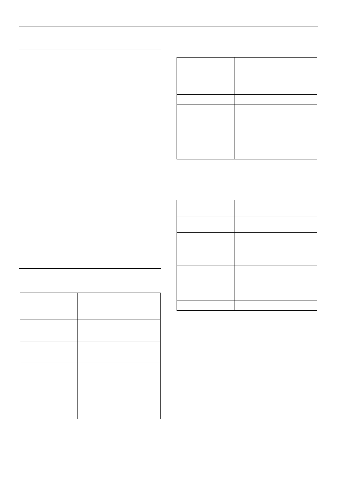
Pollution degree Pollution Degree 2,
suitable for use in residential
controls, commercial controls,
in a clean environment.
Overvoltage
category
Rated impulse
voltage
Automatic action Type 1.C
Software class
Ball-pressure test
temperature
Category II
for mains-powered (16A) controls
Category I
for 24 V powered controls
2500 VAC
(micro-interruption for the relay
outputs)
Class A
75 °C for all housing and plastic
parts
125 °C in the case of devices
applied with voltage-carrying parts
and connectors
Electromagnetic
interference
System transformer Europe: safety isolating
Table 1 System data as per EN60730-1
3 EN1B-0375GE51 R0709
Tested at 230 VAC,
with the modules in normal
condition.
transformers according to
IEC61558-2-6
U.S.A. and Canada: NEC Class-2
transformers
Page 4
System Overview Excel 800
System Overview
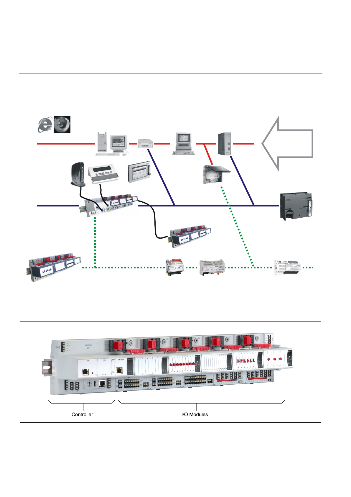
System Architecture
An Excel 800 System consists of the XCL8010 Controller and various I/O modules.
The XCL8010 Controller provides interface connections, which allow connection to external systems.
Auxiliary parts enable special features.
EBI /
SymmetrE
Ethernet LAN/WAN
Modem
XI582 or XI882A
C-Bus
XCL8010 + XF8xx
Panel Interface (<40m)
LON
LON IO (XFL8xx)
Fig. 1 Excel 800 System architecture
Internet
Browser
BNA
XLWeb
C-Bus
XFCxxx XFCLxxx
for distribution within building
OVN = OpenViewNet
IO (XF8xx)
Web-enabled
via OVN
Existing
XL500
Controllers
XL10/12
Fig. 2 XCL8010 Controller and I/O modules
EN1B-0375GE51 R0709 4
Page 5
Excel 800 System Overview
X
X
X
X
X
X
X
X
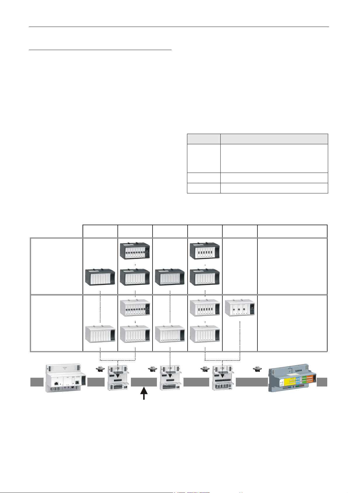
I/O Modules
Pluggable I/O Modules
There are 2 variants of pluggable I/O modules:
• Panel Bus I/O modules with communication via Panel
Bus (light-gray housings). Panel Bus I/O modules are
automatically commissioned (with firmware download) by
the XCL8010 Controller.
• L
ONWORKS Bus I/O modules (dark-gray housings) with
communication via L
compatible) for easy integration and use with 3
controllers.
Mixed I/O Modules
Besides the pluggable Panel Bus I/O modules (consisting of
a terminal socket and a removable electronic module), there
are also mixed Panel Bus I/O modules. Specifically: the
XF830A and XFU830A are mixed Panel Bus I/O modules,
featuring an integrated terminal socket and a variety of
inputs and outputs.
Mixed Panel Bus I/O modules have a light-gray housing and
are likewise automatically commissioned (with firmware
download) by the XCL8010 Controller.
ONWORKS (FTT10-A, link power
pluggable
ANALOG INPUT
pluggable
ANALOG OUTPUT
rd
-party
pluggable
BINARY INPUT
Terminal Sockets
Pluggable I/O modules must be mounted on the appropriate
terminal sockets. Pluggable Panel Bus I/O modules and
pluggable L
ONWORKS Bus I/O modules use the same
terminal sockets. These terminal sockets are available with
push-in terminals (XS82…) or with screw-type terminals
(XSU82…).
Mixed I/O modules feature an integrated terminal socket.
Color Coding
To distinguish modules and components, the following color
coding is used:
Color Part
Red All of the user-accessible adjustable
mechanical parts (i.e., bridge connectors
and locking mechanism) and operating
controls (manual overrides, etc.)
Light-gray
Dark-gray
Panel Bus I/O modules
ONWORKS Bus I/O modules
L
Table 2 Color coding of Excel 800 Modules
pluggable
RELAY OUTPUT
pluggable
FLOATING
OUTPUT
MIXED I/Os
LonWorks
BUS MODULES
XFL821A
PANEL
BUS MODULES
XF821A
XCL8010A
CONTROLLER MODULE
XS821-22
XSU821-22
LonWorks or Panel Bus
Fig. 3 Overview of I/O modules
XFLR822A
XFL822A XFL823A
XFR822A
XF822A XF823A
S823
SU823
XFLR824A
FL824A
FR824A
F824A
S824-25
SU824-25
FR825A
XF830A, XFU830A
PANEL BUS I/O MODULES
5 EN1B-0375GE51 R0709
Page 6
System Overview Excel 800
I/O Module Overview
Panel Bus
module
LONWORKS
Bus module
Description Inputs Outputs Manual controls LEDs 1)
XF821 XFL821 Analog input module 8 – – –
XF822 XFL822 Analog output module – 8 – 8 status LEDs
XFR822 XFLR822 Analog output module – 8 8 Manual overrides 8 status LEDs
XF823 XFL823 Binary input module 12 – – 12 status LEDs
XF824 XFL824 Relay output module – 6
2)
– 6 status LEDs
XFR824 XFLR824 Relay output module – 6 2) 6 Manual overrides 6 status LEDs
XFR825 – Floating output module – 3 3 Manual overrides 3 pairs of status LEDs
XF830A – Mixed I/O module 20 14 – 18 status LEDs
XFU830A – Mixed I/O module 20 14 – 18 status LEDs
1)
In addition to the power LED and service LED
2)
Changeover outputs
Table 3 Overview of I/O modules
Corresponding Terminal Sockets
I/O module
XF…
…821
…822
…823
…824
…825
Socket Scope of delivery
XS821-22
XSU821-22
XS823
XSU823
1 terminal socket,
1 bridge connector
1 swivel label holder
1 terminal socket,
1 bridge connector
1 swivel label holder
1 terminal socket,
XS824-25
XSU824-25
1 bridge connector
1 swivel label holder
1 long cross connector
Table 4 Pluggable I/O modules and corresponding
terminal sockets
Note
In the following, the Excel 800 I/O modules (Panel
Bus/L
ONWORKS Bus, with/without manual overrides) are
referred to as, e.g., …821, …822, etc.
EN1B-0375GE51 R0709 6
Page 7
Excel 800 System Overview
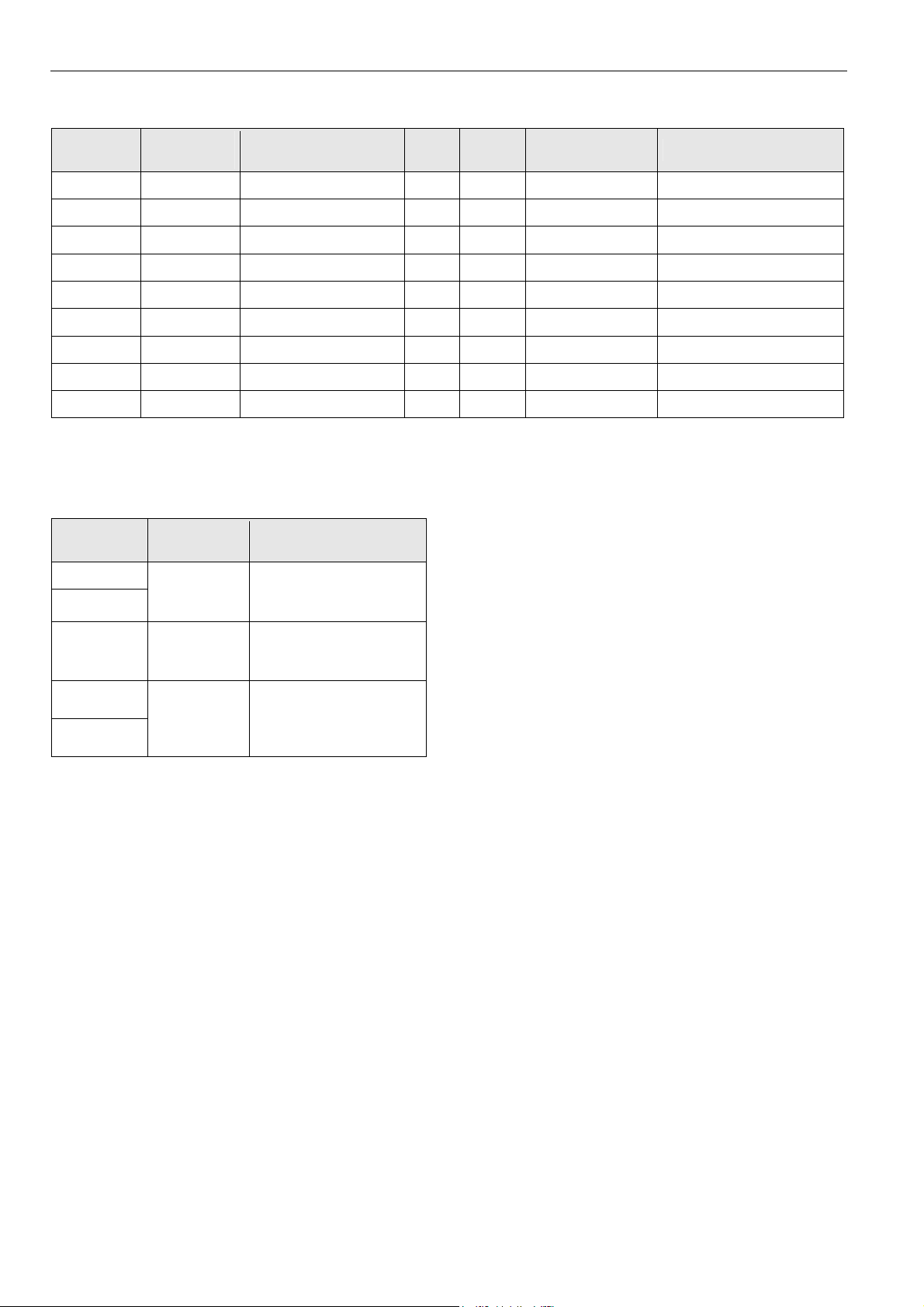
Auxiliary Parts
Module Type Figure
Corresponding
I/O modules XF…
Information
Manual disconnect
modules
Auxiliary terminal
packages
Cross connectors,
short (yellow)
XS812
XS812RO
XS814
XS830
XS831
XS817
A1 A2 A3 A4 A5 A6 A7 A8 A9 B1 B2 B3 B4 B5 B6 B7 B8 B9
A1 B1 A2 B2 A3 B3 A4 B4 G1 G2A5 B5 A6 B6 A7 B7 A8 B8
…821
…822
…823
…824
…825
Module allows disconnection
of individual I/O signals.
Module allows disconnecttion
of individual I/O signal. For
24 V applications, only.
Two groups of seven
For all pluggable Excel
800 I/O modules.
internally-connected push-in
terminals, for distributing
signals/power (see also Fig.
94).
Two groups of nine internallyconnected push-in terminals,
for distributing signals/power
(see also Fig. 96).
XF830A and XFU830A,
only.
Two groups of four pairs of
push-in terminals, for
converting 0…20 mA signals
into 0…10 Vdc signals, and
one push-in ground terminal
per group (see also Fig. 98).
Connects three relay
…824
…825
commons, required in case of
line voltage and low voltage in
the same I/O module.
Table 5 Auxiliary parts
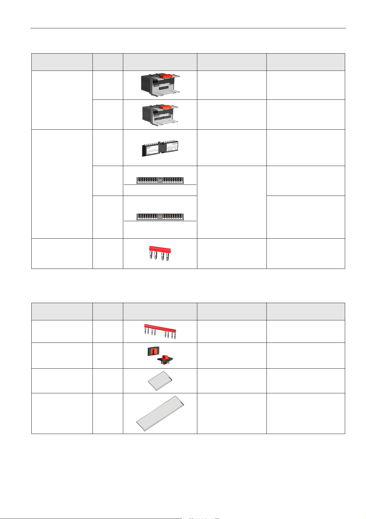
Spare Parts
Module Type Figure
Cross connectors, long
(red)
XS815
Connector bridge XS816
Swivel label holder XAL10
Swivel label holder XAL11
Table 6 Spare parts
Corresponding
I/O modules XF…
…824
…825
All Excel 800 I/O modules
Information
Connects six relay commons.
Connects XCL8010 and I/O
modules.
For all pluggable Excel
800 I/O modules
XF830A and XFU830A,
only
Can be plugged into socket,
for attaching label generated
by CARE.
Can be plugged into module,
for attaching label generated
by CARE.
7 EN1B-0375GE51 R0709
Page 8
System Overview Excel 800
Interfaces and Bus Connections
The Excel 800 System can be connected to the following
devices and systems:
Panel Bus
• For communication with up to 16 Panel Bus I/O modules
• Polarity-insensitive
L
ONWORKS Bus
• For communication with other LONWORKS Bus devices
within the building
• FTT10, link power compatible
• Polarity-insensitive
C-Bus
• For communication with other controllers, e.g., existing
Excel 500 Controllers
HMI
• For connecting an operator interface, e.g., XI582,
XI882A, or a laptop, e.g., for CARE
Modem
• For connecting a modem or an ISDN terminal adapter
Technical Data
System Data
Operating voltage 24 VAC, ± 20%, 21 … 30 VDC
Max. number of C-Bus
participants
Power consumption
30
Max. 3.57 A
(1 XCL8010 Controller
+ 16 I/O modules)
Standards
Protection class IP20
Product standard EMC EN 60730-2-9
Testing electrical
components
Certification CE
System transformer
Low-Voltage Device
Safety Assessment
Table 8 Standards
IEC68
The system transformer(s) must
be safety isolating transformers
according to IEC 61558-2-6.
In the U.S.A. and Canada, NEC
Class 2 transformers must be
used.
EN 60730-1
EN 60730-2-9
Operational Environment
Ambient operating
temperature
Ambient operating
humidity
Ambient storage
temperature
Ambient storage
humidity
Vibration under
operation
Dust, vibration According to EN60730-1
RFI, EMI Home environment
Table 9 Operational environment
0 … 50 °C (32 … 122 °F)
5 … 93% relative humidity
(non-condensing)
–20 … 70 °C (–4 … +158 °F)
5 … 95% relative humidity
(non-condensing)
0.024” double amplitude
(2 … 30 Hz),
0.6 g (30 … 300 Hz)
Push-in terminals 1.5 mm2
Screw-type terminals 1.5 mm2
Overvoltage protection
Calculated lifetime of
weakest component
under typical operating
conditions
Table 7 System data
EN1B-0375GE51 R0709
All inputs and outputs are
protected against 24 VAC and
40 VDC overvoltage as well as
against short-circuiting.
MTBF
≥ 13.7 years
8
Page 9
Excel 800 Planning
Planning
Overview
Engineering with CARE
During CARE engineering, the type of I/O modules, terminal
assignment and module configuration are defined
depending on the application.
Planning
In this step, the following has to be defined, if applicable:
• Power supply
• Fusing
• Earth grounding
• Lightning protection
• Panel Bus wiring
• Design of a L
• Design of a C-Bus network
• Useful accessories
• Cable selection
ONWORKS network
Transformer Selection
Note
In Europe the system transformer(s) must be safety isolating
transformers according to IEC61558-2-6.
In the U.S.A. and Canada, NEC Class-2 transformers must
be used.
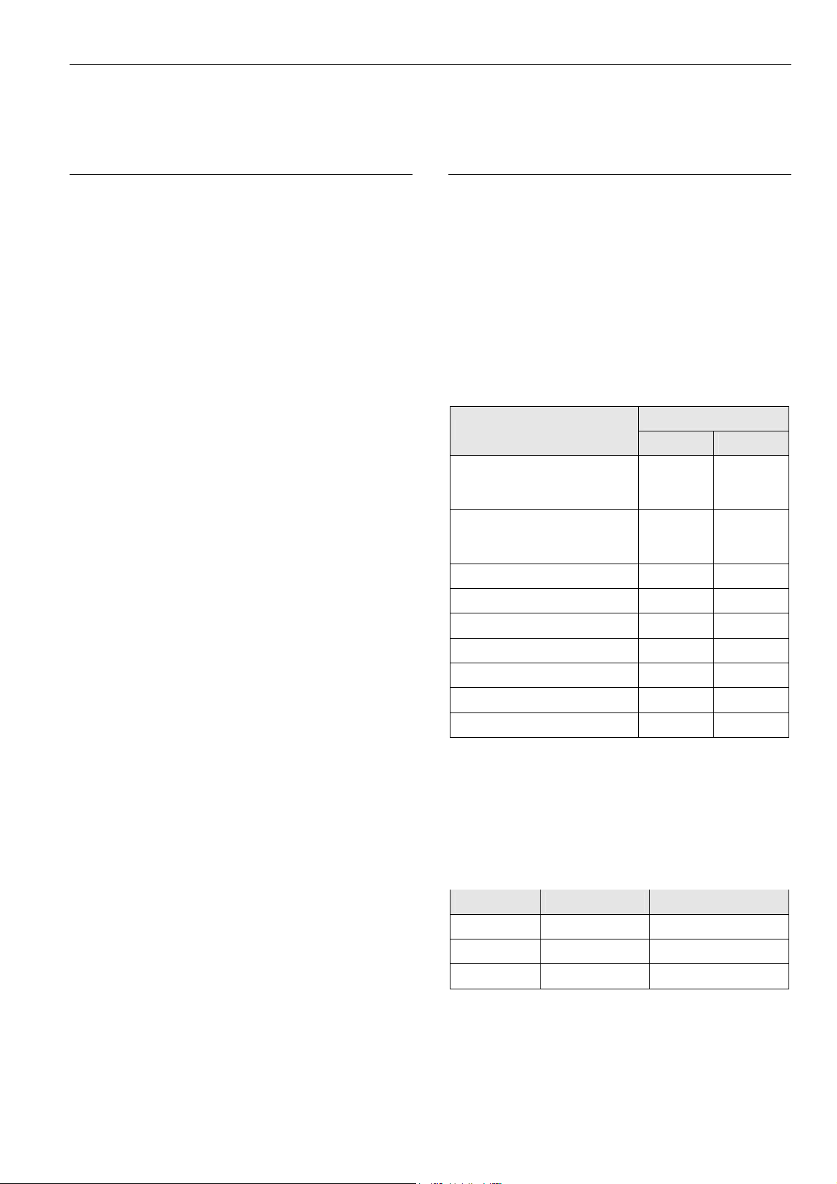
Power Consumption
When selecting the appropriate transformer, take into
account the number of individual modules, accessories, and
field devices in determining the total power consumption.
Devices powered
XCL8010 with XI582
(backlight ON) and with
watchdog load (max. 500 mA)
XCL8010 with XI582
(backlight ON) but without
watchdog load
Power consumption
24 VAC 24 VDC
690 mA 640 mA
190 mA 140 mA
…821 130 mA 80mA
…822 160 mA 90 mA
…823 180 mA 130 mA
…824 140 mA 90 mA
…825 140 mA 90 mA
XF830A 200 mA 95 mA
XFU830A 200 mA 95 mA
Table 10 Power consumption of Excel 800 System
components depending on power supply
Connectable Power Supplies
Honeywell CRT Series (Europe)
Transformer Primary side Secondary side
CRT 2 220/230 VAC 24 VAC, 50 VA, 2 A
CRT 6 220/230 VAC 24 VAC, 150 VA, 6 A
CRT 12 220/230 VAC 24 VAC, 300 VA, 12 A
Table 11 Honeywell CRT series transformers data
9 EN1B-0375GE51 R0709
Page 10
Planning Excel 800
Honeywell 1450 Series (North America)
• 50/60 Hz
• Insulated accessory outputs
• Built-in fuses
• Line transient /surge protection
• AC convenience outlet
• NEC Class-2
Part number
1450 7287
-001 120 VAC 24 VAC, 50 VA
-002 120 VAC
-003 120 VAC
-004 240/220 VAC 24 VAC, 50 VA
-005 240/220 VAC
-006 240/220 VAC
Table 12 Honeywell 1450 series transformers data
Standard Transformers (Europe, North America)
Standard commercially available transformers used to
supply power to Excel 800 Systems must fulfill the following
specifications:
Output voltage Impedance AC current
Primary side Secondary side
2 x 24 VAC, 40 VA,
and 100 VA from separate
transformer
24 VAC, 100 VA,
and 24 VDC; 600 mA
2 x 24 VAC, 40 VA,
and 100 VA from separate
transformer
24 VAC, 100 VA, and
24 VDC, 600 mA
Power Supply of Field Devices
Depending upon the power consumption of the field devices
used, it is possible to use either a single transformer to
power both the XCL8010 Controller and attached field
devices, or it may be necessary to employ an additional
transformer. See also section "Field Device Cables" on
page 13 and connection examples on page 29.
Fusing Specifications
For connection examples see description of the I/O modules
on page 39 and following.
F1 (Fusing for XCL8010 Controller and I/O Modules)
Rating: 4 A, time-lag fuse (slo-blo)
For example:
Manufacturer: Littlefuse
Type: 218004
F2 (Fusing for Active Field Devices)
Depends upon loads in use.
System Protective Earth Grounding
Excel 800 Systems comply with SELV (Safety Extra-Low
Voltage). Earth grounding is therefore not recommended.
However, if compliance with EN60204-1 is required, see
Appendix 1.
Lightning Protection
24.5 VAC to 25.5 VAC
24.5 VAC to 25.5 VAC
24.5 VAC to 25.5 VAC
Table 13 Requirements for standard transformers
RIN-APU24 Uninterruptable Power Supply
The RIN-APU24 Uninterruptable Power Supply can be wired
to power Excel 800 Systems.
See also RIN-APU24 Uninterruptable Power Supply –
Mounting Instructions (MU1B-0258GE51) for detailed wiring
diagrams.
EN1B-0375GE51 R0709
≤ 1.15 Ω
≤ 0.40 Ω
≤ 0.17 Ω
max. 2 A
max. 6 A
max. 12 A
Please contact your local Honeywell representative for
information on lightning protection.
Panel Bus Topologies
• Up to 16 Panel Bus I/O modules can be controlled by a
single XCL8010 Controller.
• Panel Bus I/O modules must be addressed using the
HEX switch.
• Maximum distance between controller and Panel Bus
I/O module: 40 m.
• No bus termination
• Polarity-insensitive
10
Page 11
Excel 800 Planning
LONWORKS Bus Topologies
The LONWORKS Bus is a 78-kilobit serial link that uses
transformer isolation so that the bus wiring does not have a
polarity. I.e. it is not important which of the two LONWORKS
Bus terminals are connected to each wire of the twisted pair.
The L
ONWORKS Bus does not need to be shielded on the
controller module side.
The LONWORKS Bus can be wired in daisy chain, star, loop
or any combination thereof as long as the maximum wire
length requirements are met.
Configuration
The recommended configuration is a daisy chain with two
bus terminations. This layout allows for max. L
ONWORKS
Bus lengths, and its simple structure presents the least
number of possible problems, particularly when adding on to
an existing bus.
See also “L
ONWORKS Mechanisms”, Product Literature no.:
EN0B-0270GE51.
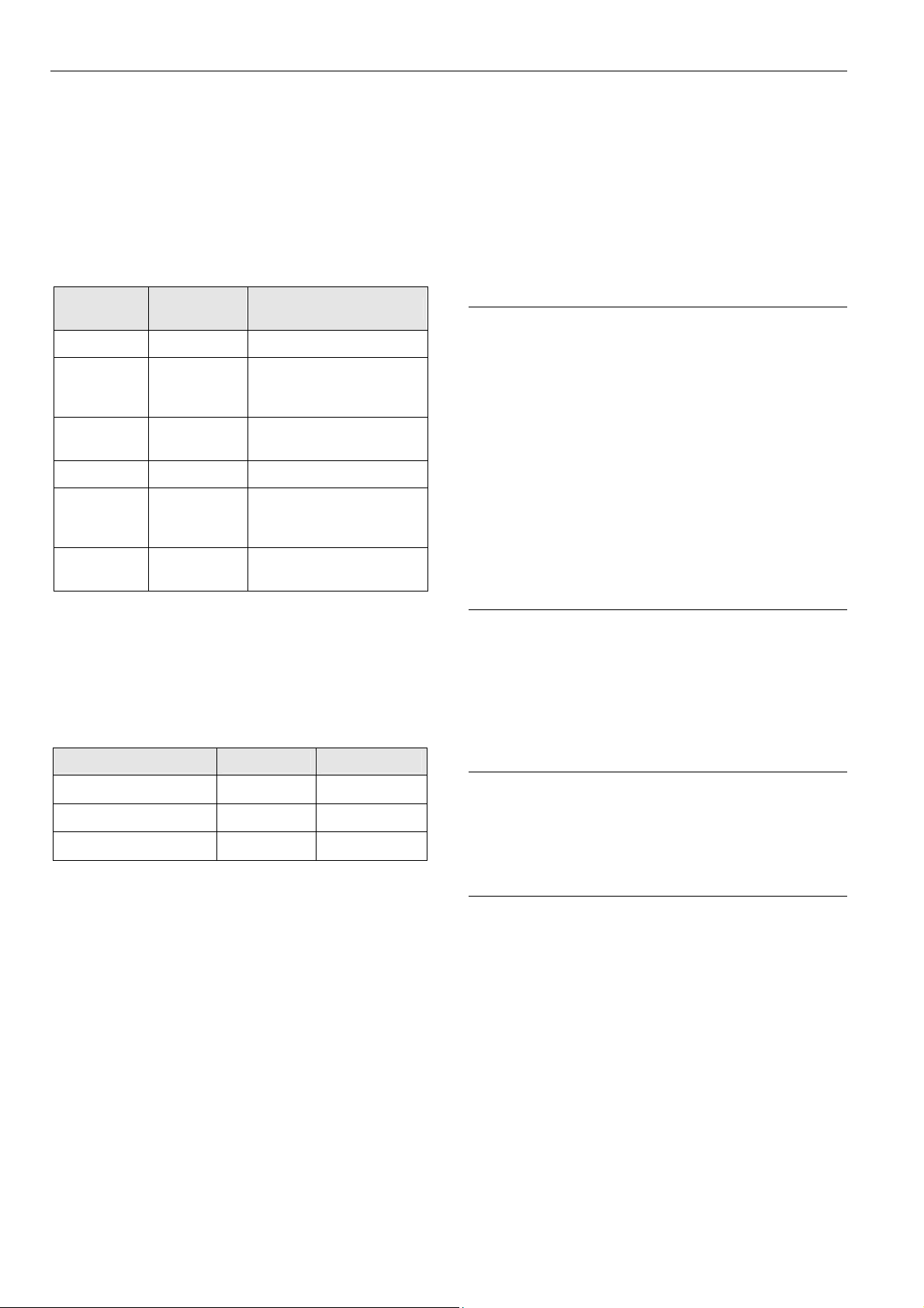
C-Bus Topologies
Accessories
Besides the auxiliary parts of Table 5 on page 7, the
following accessories are available.
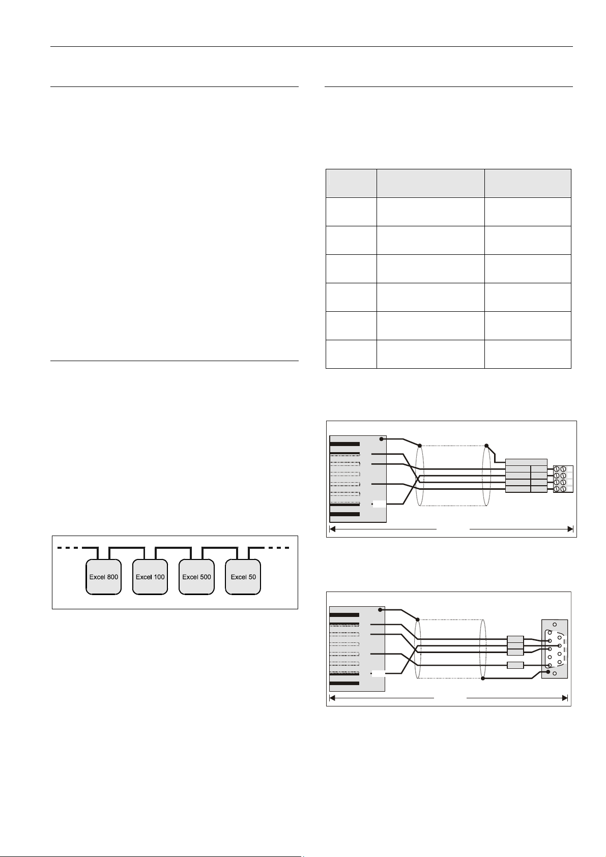
Preconfigured Connection Cables
Type
XW882 XI582 Operator Interface
XW582
+ XW586
XW884
XW885 Laptops
XW585
+ XW586
XW586 Modems
Connecting XCL8010
Controller with
XI582 Operator Interface
Adapter cable for Excel
500/600 Controllers
Laptops
Features
5 m, shielded,
RJ45 plug with clip
See XW582 and
XW586
0.2 m, shielded,
RJ45 – 9 pin sub-D
3 m, shielded,
RJ45 plug with clip
See XW582 and
XW586
1.8 m, RJ45 – 9 pin
sub-D
Via the C-Bus up to 30 C-Bus devices (e.g., controllers, etc.)
can communicate with one another and a PC central. The
C-Bus must be connected via the individual controllers
(open ring).
Note
Star connection is not allowed because uncontrollable line
reflections may occur.
Instead of an Excel 800 Controllers, other C-Bus controllers
(e.g., the Excel 500, Excel 100, Excel 50) can also be
connected.
Fig. 4 C-Bus topology Excel 5000
Table 14 Preconfigured connection cables
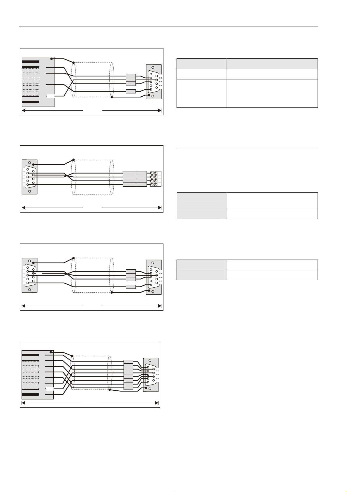
XW882 Cable Details
RJ45 plug with clip at front
12
SHIELD
3678
4
5
+5V
XW882
Fig. 5 XCL8010/XI582 cable details
XW884 Cable Details
RJ45 plug with clip at front
12
SHIELD
3678
4
5
+5V
LOOSE
ENDS
R
G
L
E
Y
R
B
G
R
W
H
sub-D female
R
x
R
T
T
x
G
N
XI582
WIRING
TERMINALS
A
Y
n
(
d
e
)
s
u
t
o
W
O
L
T
D
x
W
O
E
V
+
5
N
R
N
E
E
D
x
N
G
D
E
T
I
RS232 plug
1
D
S
D
D
2
3
4
5
1
2
3
4
6
7
8
9
XW884
Fig. 6 XCL8010/Excel 500/600 cable details
11 EN1B-0375GE51 R0709
Page 12
Planning Excel 800
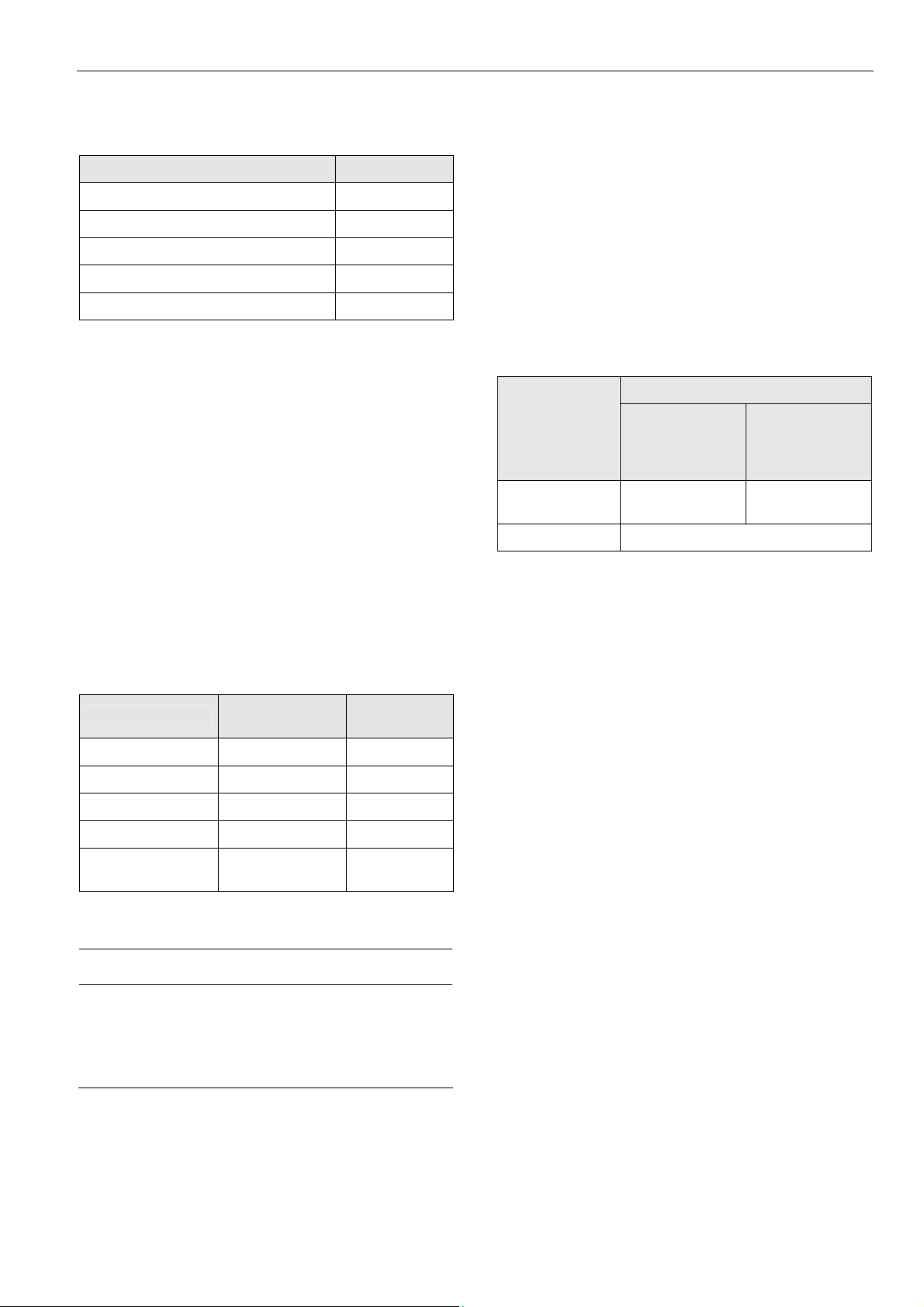
XW885 Cable Details
RJ45 plug with clip at front
12
SHIELD
3678
4
5
+5V
XW885
Fig. 7 XCL8010/laptop cable details
XW582 Cable Details
to XC5010C
1
6
2
7
3
8
4
9
5
SHIELD
XW582
Fig. 8 XW582 cable details
XW585 Cable Details
RS232 plug
sub-D female
1
6
2
7
+5V
3
8
4
9
5
SHIELD
RS232 plug
sub-D female
x
R
R
T
T
x
N
G
LOOSE
ENDS
TERMINALS
O
L
L
E
Y
W
O
R
B
G
E
E
R
W
T
I
H
RS232 plug
sub-D female
R
x
R
T
T
x
N
G
D
S
D
D
W
N
N
E
D
S
D
D
XI582
WIRING
D
x
T
E
V
+
5
R
D
x
D
N
G
LONWORKS Bus Termination Modules
Type Description
1
209541 LONWORKS Bus termination module
6
2
7
3
8
4
5
9
XAL-Term
L
ONWORKS connection and
termination module, which can be
mounted on DIN rails and in fuse
boxes
Table 15 LONWORKS Bus termination modules
Cable Specifications
Power Supply Cables
When checking the length of the power supply cable, the
1
2
3
4
1
2
3
4
5
connection cables to all I/O modules must be taken into
account.
Max. length 3 m (per side of the controller),
see Fig. 33 on page 25
Cross section
min. 0.75 mm
2
(AWG 18)
Table 16 Power supply cables specification
Panel Bus Cables
Max. length
6
7
Cable type
8
9
Table 17 Panel Bus cables specification
40 m
twisted pair, e.g., J-Y-Y 2 x 2 x 0.8
XW585
Fig. 9 XW585 cable details
XW586 Cable Details
RJ45 plug with clip at front
12
SHIELD
3678
4
5
+5V
RS232 plug
sub-D male
D
C
D
R
S
D
D
x
R
S
R
T
D
x
T
S
T
C
D
R
T
G
D
N
1
2
3
4
5
XW586
Fig. 10 XW586 cable details
EN1B-0375GE51 R0709
6
7
8
9
12
Page 13
Excel 800 Planning
LONWORKS Bus Cables
Cable type Max. bus length
Belden 85102 (plenum) 2700 m (8900 ft)
Belden 8471 (non-plenum) 2700 m (8900 ft)
Level IV, 22 AWG 1400 m (4600 ft)
JY (St) Y 2 x 2 x 0.8 900 m (3000 ft)
TIA568A Cat. 5 24AWG, twisted pair 900 m (3000 ft)
Table 18 Doubly-terminated bus specifications
Notes
• The cable types listed above are as recommended by
Echelon in their FTT-10A User Guide.
• The cable recommended by Honeywell is the level IV,
22 AWG, solid core, non-shielded cable.
• Belden part numbers are 9H2201504 (plenum) and
9D220150 (non-plenum).
FTT Specification
The FTT specification includes two components that must
be met for proper system operation:
• The distance from each transceiver to all other
transceivers and to the termination must not exceed the
max. node-to-node distance.
• If multiple paths exist, the maximum total wire length is
the total amount of wire used.
Cable type
Max. node-tonode distance
Max. total wire
length
Note
In the event that the limit on the total wire length is
exceeded, the FTT physical layer repeaters (FTT 10A) can
be added to interconnect segments. This increases the
overall length by an amount equal to the original
specification for that cable type and bus type for each
repeater used.
For example, adding repeaters for a doubly-terminated bus
using JY (St) Y 2 x 2 x 0.8 cable increases the maximum
length 900 m (3000 ft) for each repeater.
Field Device Cables
Cross-sectional area
Type of signal
24 VAC power
0…10 V signals 0.081 – 2.08 mm2 (28 – 14 AWG)
Table 20 Cable sizing for connection of field devices
For wiring field devices see page 29.
≤ 100 m (300 ft)
(Fig. 40 on p. 29)
one transformer
1.5 mm2
(16 AWG)
≤ 400 m (1300 ft)
(Fig. 41 on p. 29)
separate
transformers
not allowed for
> 100 m (300 ft)
Belden 85102 500 m (1650 ft) 500 m (1650 ft)
Belden 8471 400 m (1300 ft) 500 m (1650 ft)
Level IV, 22AWG 400 m (1300 ft) 500 m (1650 ft)
JY (St) Y 2 x 2 x 0.8 320 m (1050 ft) 500 m (1650 ft)
TIA568A Cat. 5
24AWG, twisted pair
Table 19 Free topology (singly-terminated) specifications
250 m (825 ft) 450 m (1500 ft)
NOTICE
Unpredictable reflections on the bus due to step change
in line impedance characteristics!
► Do not use different wire types or gauges on the same
ONWORKS network segment.
L
13 EN1B-0375GE51 R0709
Page 14

Planning Excel 800
C-Bus Cables
Note
Observe national regulations for C-Bus cables!
• For Europe, only shielded cable is permitted.
• For the U.S., shielded or unshielded cable can be used.
Cable type Description Recommended for
J-Y-(ST)Y
2 x 2 x 0.8
A-Y-(ST)Y
2 x 2 x 0.8
AK 3702
AK 3740A shielded
Belden 9842 twisted pair Europe, US also possible
Belden 9841 shielded US
AK 3702
AK 3740A shielded
Table 21 C-Bus cable types
Maximum Cable Length
The maximum C-Bus cable length is 1200 m (4000 ft).
See section "C-Bus Topologies" on page 11.
shielded,
twisted pair
shielded,
twisted pair
unshielded,
twisted pair
unshielded,
twisted pair
Europe, inside cabinet
Europe, outside cabinet
US
not approved for Europe
US (low-cost)
not approved for Europe
US
not approved for Europe
US (low-cost)
not approved for Europe
EN1B-0375GE51 R0709
14
Page 15
Excel 800 Planning
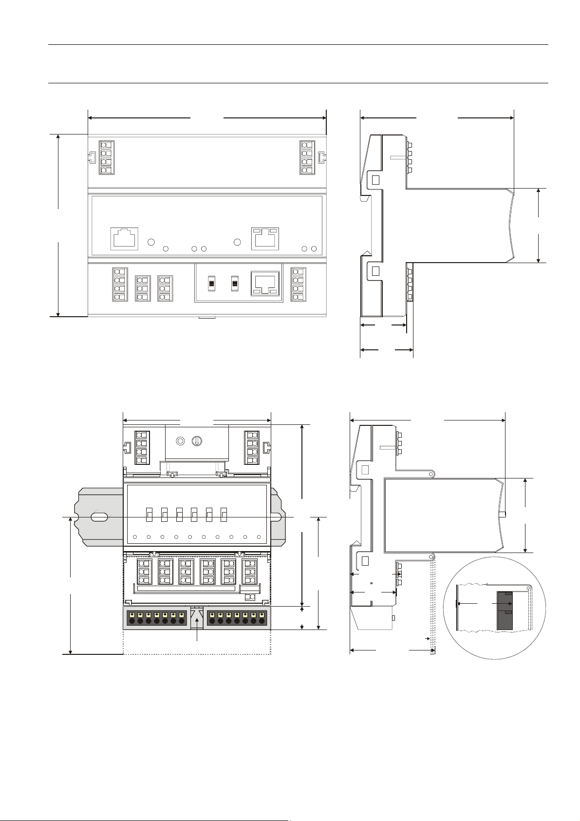
Dimensions
Controller Module
144
110
Fig. 11 Controller module, dimensions (in mm)
28
32
92.75
45
Pluggable I/O Modules
89.5 94.1
LOCK
45
83
110
67.5
30.6
28
SCREW-TYPE
TERMINALS
38
14
XS814 Aux. Terminal Package (optional)
SWIVEL LABEL HOLDER
51.5
Fig. 12 Pluggable I/O modules (shown with manual overrides), including XS814 Aux. Terminal Package, dimensions (in mm)
15 EN1B-0375GE51 R0709
Page 16
Planning Excel 800
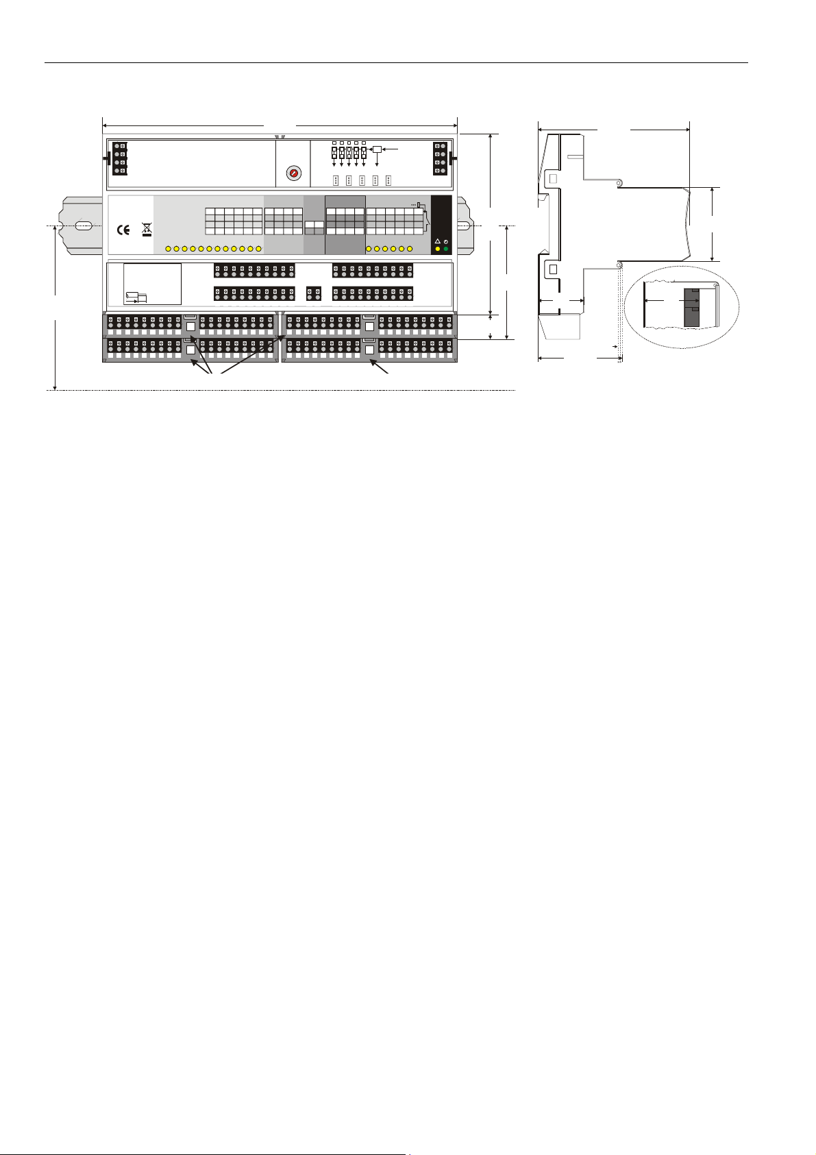
Mixed I/O Modules
216
75
71
COM a
COM b
72
24V~
100
73
24V~0
74
1 12 23 34 45 56 67
Install. Instr.
DI
EN1B-0375GE51
XF830A
12 BI / 8 AI / 8 AO / 6 RO
24V, 15VA, T50
0706AX0001-XFU830A
8
Made in Germany
0532
A5 A6 A7 A8 A9
A1 A2A3A4
CLEARANCE
A1 A2 A3 A4 A5 A6 A7 A8 A9 B1 B2 B3 B4 B5 B6 B7 B8 B9
A
C
Binary Inputs
B8 B9 B10
B7
B11B12
7
8 9 10
11 12
1 2 3 4 5 6
B5 B6
B1 B2B3B4
8 9310411512
7 8 9
10 11 12 17 18 19 20
1 21 222324
2
B5 B6 B7 B8 B9
B1 B2B3B4
4
5
3
6
2
7
24V for relay 1...5
1
8
0
9
S2
F
A
E
B
C
D
J1 J2 J3 J4 J5
Analog Inputs Analog Outputs 24V Relays
AI6
AI7
18 19 20
17
13 14 15 16
AI3
GND
AI8
AO5
AO6 AO7 AO8
25
262728 35
G1 G2
21 22 23 24
AI4 41
42
AO1 AO2 AO 3 AO4 NO1 NO2 NO3 NO4 NO5 NO6
AI5
AI1 AI2
25 26 27 28 35 36 37 38 39 40
6 131415 16
41 42
A5 A6 A7 A8 A9
A1 A2A3A4
A1 B1 A2 B2 A3 B3 A4 B4 G1 G2A5 B5 A6 B6 A7 B7 A8 B8
D = XS831 Aux. Terminal Package (optional)A, B, and C = XS830 Aux. Terminal Packages (optional)
Fig. 13 Mixed Excel 800 I/O Modules (example shows XF830A with four auxiliary terminal packages), dimensions (in mm)
External
COM a
40
24V
COM b
IN3
IN1 IN2
IN4
36 37 38 39 40
29 30 31 32 33 34
29 30 31 32 33 34
B
B1 B2B3B4
D
24V~
24V~0
IN5 IN6
DO
B5 B6 B7 B8 B9
76
77
78
Honeywell
!
110
69
28
15
SWIVEL LABEL HOLDER
51.5
92.5
38
SCREW-TYPE TERMINALS
(XFU830A)
45
EN1B-0375GE51 R0709
16
Page 17
Excel 800 Mounting/Dismounting Modules
A
A
Mounting/Dismounting Modules
WARNING
Risk of electric shock or equipment damage!
► Do not touch any live parts in the cabinet.
► Disconnect the power supply before you start to install
the Excel 800 System.
More than one disconnect switch may be required to deenergize the system.
► Do not reconnect the power supply until you have
completed the installation.
Note
The terminal socket of each pluggable I/O module can be
mounted and wired before inserting and locking the
corresponding electronic module.
1 2
71 COM a
72 COM b
73 24V
~
74 24V 0
~
C-BUS RESET
9.6k all
76k
76k
C-Bus
S1 S2
PC/HMI
Modem
Panel
mid
LON
end
I/O Bus
Rx Tx
LON
8765 4 32 1 8765 4 32 1
11 1
12 285
13 396
14 410 7
C-Bus
C-Bus
LON
out
in
4
S1 S2
71 COM a
5
4
3
6
2
7
1
8
0
9
F
A
72 COM b
E
B
D
C
73 24V
~
74 24V 0
~
1
2
AAA
21
31
11
22
32
12
23
33
13
14 4424 5434 64 25
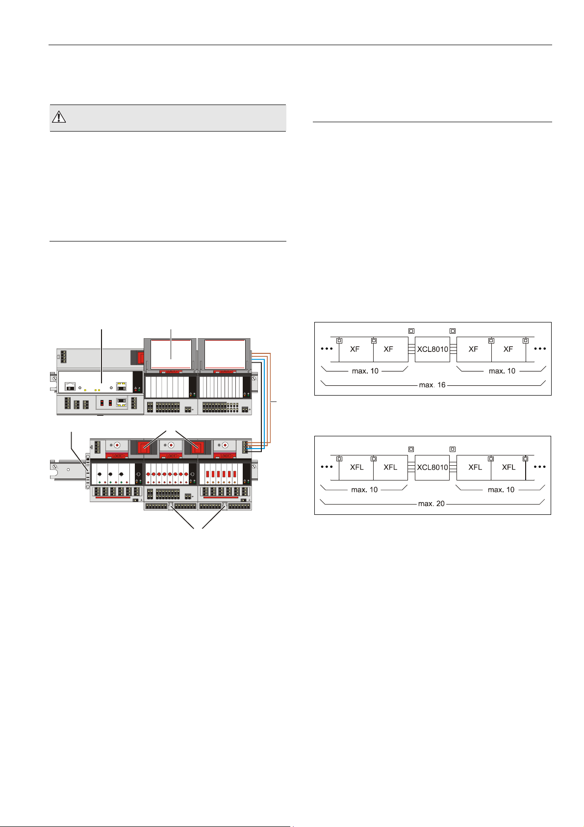
Fig. 14 XCL8010
mounted on multiple DIN rails
1:ABCDFERTAQWESDERT1
2:ABCDFERTAQWESDERT2
3:ABCDFERTAQWESDERT3
4:ABCDFERTAQWESDERT4
5:ABCDFERTAQWESDERT5
PRESS
COM a
6:ABCDFERTAQWESDERT6
COM b
7:ABCDFERTAQWESDERT7
8:ABCDFERTAQWESDERT8
24V
~
24V 0
~
PRESS
Honeywell
!
8765 4 32 1
Power/
Alarm
5678
1234
21
22 12345678
AUX
GND GND
9
10 11 12 13 14 15 16 17 18 25 26
5
PRESS
3
41
51
42
52
43
53
Controller Module and I/O modules
PRESS
Honeywell
1234
0
100
AUTO
AAAAA
!
21
22 12345678
616261
62
AUX
6363
GND GND
9
10 11 12 13 14 15 16 17 18 25 26
S1 S2
5
4
3
6
2
7
1
8
0
9
F
A
E
B
D
C
5678
Honeywell
!
AI/AOV
PRESS
Honeywell
0
AUTO
A
!
AI/AOV
1:ABCDFERTAQWESDERT1
2:ABCDFERTAQWESDERT2
3:ABCDFERTAQWESDERT3
4:ABCDFERTAQWESDERT4
5:ABCDFERTAQWESDERT5
6:ABCDFERTAQWESDERT6
7:ABCDFERTAQWESDERT7
8:ABCDFERTAQWESDERT8
5 6 7 8 9 10
1 234
123456789101112
BI
GND
13 14 15 16 17 18 19 20 21 22 23 24 25 26
S1 S2
PRESS
1234
100
21
31
11
22
32
12
23
33
13
14 4424 5434 64 25
6
Honeywell
11 12
!
5
4
3
6
2
7
1
8
0
9
F
A
E
B
D
C
Honeywell
56
--1
--0
--AUTO
!
41
51
616261
42
52
62
43
53
6363
Mounting/Dismounting Controller/Sockets
Mounting Sockets
Notes
• When using both Panel Bus and LONWORKS Bus I/O
modules in an Excel 800 System, group both Panel Bus
modules (light-gray) and LONWORKS Bus I/O modules
(dark-gray), e.g., on different rails.
• Up to 10 Panel Bus I/O modules can be mounted to one
side of the controller. In total, up to 16 Panel Bus
I/O modules can be mounted to one controller.
• The XCL8010 Controller Module and the mixed Panel
Bus I/O modules are mounted on the DIN rail in the same
way as a terminal socket.
3
Fig. 15 Max. number of Panel Bus I/O modules
Fig. 16 Max. number of L
power supply via XCL8010
ONWORKS Bus I/O modules with
Legend
1 XCL8010 Controller Module
2 Swivel label holder
3 Cable connection
4 Stopper (from 3
rd
-party supplier)
5 Bridge connectors
6 Auxiliary terminal packages
17 EN1B-0375GE51 R0709
Page 18
Mounting/Dismounting Modules Excel 800
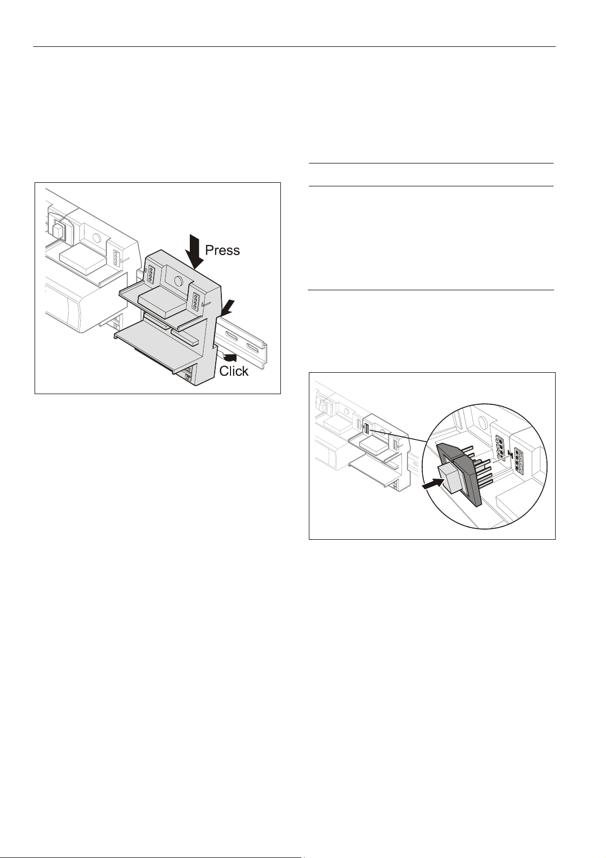
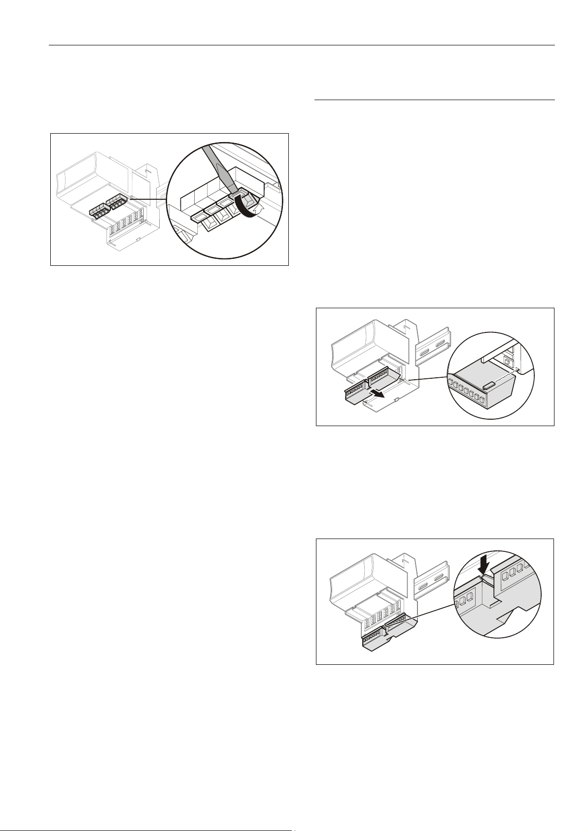
► Angle the terminal socket at the upper edge of the DIN
rail until it snaps in.
► Swing the terminal socket down and apply gentle force
until it snaps into position with an audible "click".
► Position controller module and terminal sockets flush with
one another along the rail.
► If desired, mount stoppers at the ends of the rail to
prevent sliding.
Connecting Sockets
Controller, terminal sockets, and mixed I/O modules on the
same DIN rail can be connected mechanically and
electrically with bridge connectors.
Controller and terminal sockets on different DIN rails must
be connected using cables, see Fig. 14 and page 24.
NOTICE
Risk of malfunction!
► Wire Panel Bus I/O modules and LONWORKS Bus
I/O modules separately.
► When using both Panel Bus and LONWORKS Bus
I/O modules in an Excel 800 System, L
I/O modules must be connected to the controller via
LON terminals 11 … 14.
Position the bridge connector on terminals 71 … 74 of the
right-hand terminal socket or mixed I/O module or controller
and on terminals 75 … 78 of the left-hand terminal socket or
mixed I/O module or controller. Then press the bridge
connector down.
ONWORKS Bus
Fig. 17 Mounting terminal sockets
Note
Take care to not bend the Omega clamp, which serves to
establish the electrical contact with the DIN rail and which
located on the back of the terminal socket.
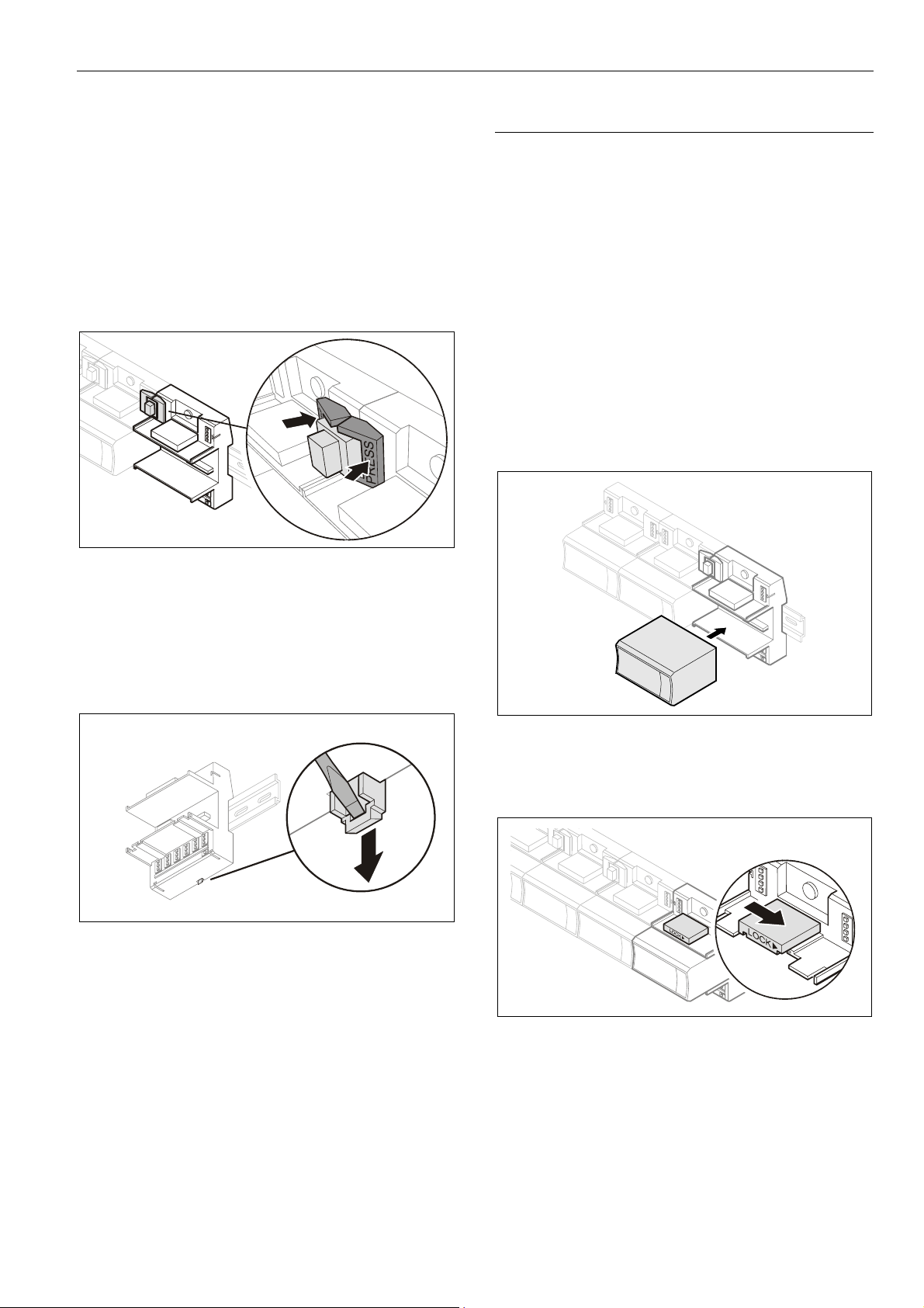
Fig. 18 Connecting terminal sockets with bridge
connector
Notes
• Bridge connectors transmit both communication signals
and power supply between modules.
• Removing bridge connectors will interrupt the trans-
mission of both communication signals and power supply
between the modules.
EN1B-0375GE51 R0709
18
Page 19
Excel 800 Mounting/Dismounting Modules
Dismounting Sockets
Disconnecting Sockets
Release all bridge connectors before removing the controller
module and/or the terminal sockets and/or mixed I/O
modules from the DIN rail.
► Press down at the same time both the gray side wings
next to the red button and then pull the bridge connector
out of the module.
Fig. 19 Releasing bridge connectors
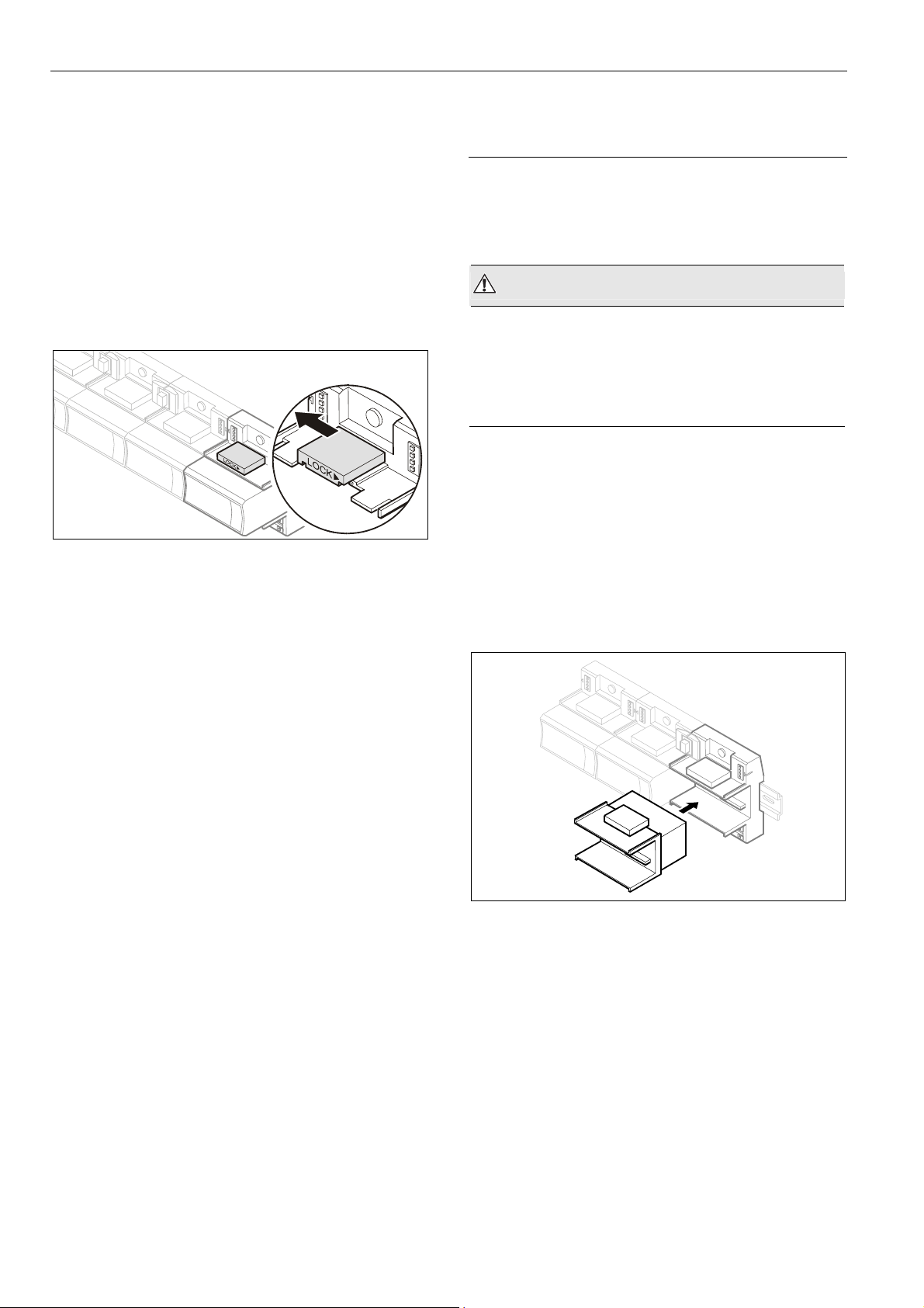
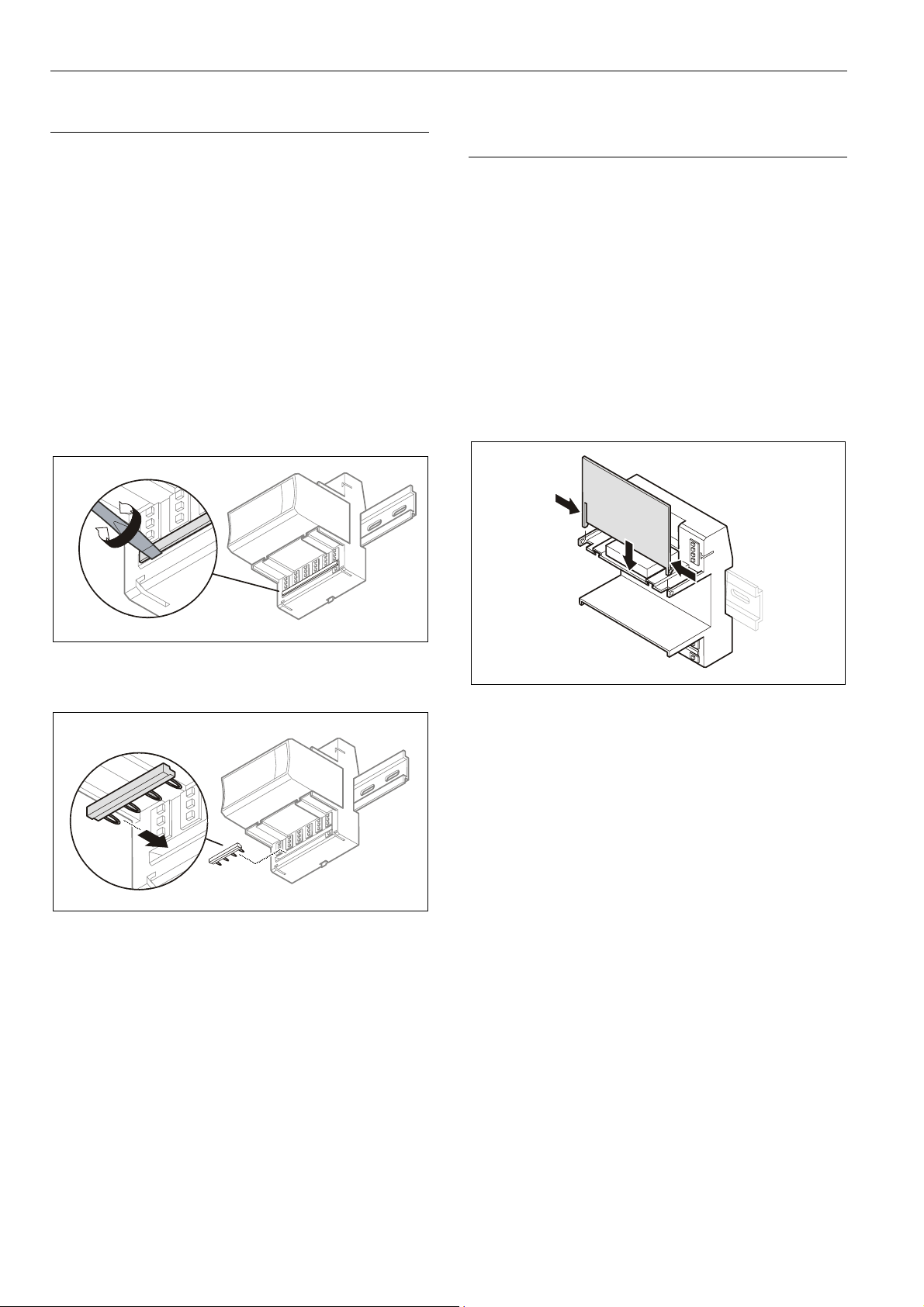
Mounting/Dismounting Electronic Modules
Mounting Electronic Modules
Note
Electronic modules can be removed from or inserted into the
sockets without switching off the power supply. The
behavior of connected field devices must be taken into
consideration.
► Make sure that terminal socket and electronic I/O module
match, see Table 4 on page 6.
► Make sure that the red locking mechanism is in the open,
i.e., left, position.
► Gently push the electronic module onto the terminal
socket until snug.
Dismounting Controller / Terminal Sockets / Mixed I/O
Modules
► Insert a screwdriver into the latch on the underside of the
module and lever the red latch 2–3 mm downwards. The
module can then be swung away from the rail.
Fig. 20 Releasing latch
Fig. 21 Inserting the electronic module
► Lock the red locking mechanism by sliding it to the right.
Fig. 22 Locking the electronic module
Note
The red locking mechanism will not close if the electronic
module is not properly mounted.
19 EN1B-0375GE51 R0709
Page 20
Mounting/Dismounting Modules Excel 800
Dismounting Electronic Modules
Note
Electronic modules can be removed from or inserted into the
sockets without switching off the power supply. The
behavior of connected field devices must be taken into
consideration.
► Open the red locking mechanism by sliding it to the left
and then gently pull the electronic module out of the
terminal socket.
Fig. 23 Dismounting the electronic module
Mounting/Dismounting Manual Disconnect
Modules
XS812 and XS812RO Manual Disconnect Modules are
mounted on the terminal socket appropriate for the
electronic module, see Table 4 on page 6. The electronic
module is mounted onto the manual disconnect module.
WARNING
Risk of electric shock or equipment damage!
The XS812RO Manual Disconnect Module is designed
for 24 V applications only!
► Never use the XS812RO Manual Disconnect Module with
line voltage.
Mounting Manual Disconnect Modules
► Make sure that manual disconnect module, electronic
module, and terminal socket match, see Table 4 on
page 6.
► Make sure that the red locking mechanism is in the open,
i.e., left, position.
► Gently push the manual disconnect module onto the
terminal socket until snug.
► Lock the red locking mechanism by sliding it to the right.
EN1B-0375GE51 R0709
Fig. 24 Mounting the manual disconnect modules
20
Page 21
Excel 800 Mounting/Dismounting Modules
Operating the Individual Switches
► Use a screwdriver to open/close the appropriate
disconnector switches of the manual disconnect
modules.
Fig. 25 Operating the disconnector switches
Dismounting Manual Disconnect Modules
► Open the red lock mechanism by sliding it to the left and
then gently pull the electronic module out of the terminal
socket.
Mounting/Dismounting Auxiliary Terminal
Packages
The XS814 Auxiliary Terminal Package can be mounted on
any pluggable I/O module.
The XS830 and XS831 Auxiliary Terminal Packages are
suitable for mixed I/O modules, only. Specifically, they can
be mounted on the top and/or bottom of the XF830A and on
the bottom of the XFU830A.
For reasons of mechanical stability, a maximum of two rows
of Auxiliary Terminal Packages may be mounted together
on any given I/O module.
Mounting Auxiliary Terminal Packages
► Push the auxiliary terminal package onto the grooves of
the corresponding terminal socket / the mixed I/O
module.
Fig. 26 Mounting the auxiliary terminal package onto the
terminal socket / mixed I/O module
Dismounting Auxiliary Terminal Packages
► Push down the catch of the auxiliary terminal package
and pull it out of the grooves of the terminal socket / the
mixed I/O module.
Fig. 27 Dismounting the auxiliary terminal package from
the terminal socket / the mixed I/O module
21 EN1B-0375GE51 R0709
Page 22
Mounting/Dismounting Modules Excel 800
Mounting/Dismounting Cross Connectors
Note
The long cross connector (incl. in the scope of the delivery)
can be mounted to the XS824-25 or XSU824-25, as
required (see Fig. 29). It can be dismounted (see Fig. 28)
and, if desired, replaced with one or two short connectors
(optional accessory, see Table 5 on page 7). It is not
permitted to replace these cross connectors with wire.
► Insert a screwdriver on one end of the cross connector
and swivel it to the right and to the left.
► Insert a screwdriver on the other end of the cross
connecter and swivel it to the right and to left until the
cross connector is released.
► If desired, insert another cross connector.
Mounting/Dismounting Swivel Label
Holders
Note
A swivel label holder is included in the scope of delivery of
each module.
Use only the (short / long) swivel label holders appropriate
for the given type (pluggable or mixed, respectively) of I/O
module.
Mounting Swivel Label Holders
► Snap the swivel label holder onto the hinges of the
terminal socket / mixed I/O module.
► Apply self-adhesive labels to the holders.
Fig. 28 Dismounting the cross connectors (long cross
connector shown here)
Fig. 29 Mounting the cross connectors (short cross
connector shown here)
Fig. 30 Mounting the swivel label holder
Dismounting Swivel Label Holders
► Press the hinges together and remove the swivel label
holder.
EN1B-0375GE51 R0709
22
Page 23
Excel 800 Wiring and Setting Up the System
Wiring and Setting Up the System
General Safety Considerations
• When connecting the XCL8010 Controller Module or
Excel 800 I/O modules, both VDE, National Electric Code
(NEC) or equivalent, and any local regulations concerning grounding and zero voltage must be observed.
• Electrical work should be carried out by a qualified
electrician.
• The electrical connections must be made at the terminal
blocks. The corresponding connection diagrams are
located on the individual controller module and
I/O modules.
• For Europe only: To comply with CE requirements,
devices with a voltage in the range of 50 ... 1000 VAC or
75 ... 1500 VDC, which are not provided with a supply
cord and plug or with other means for disconnection from
the supply having a contact separation of at least 3 mm
in all poles, must have the means for disconnection
incorporated in the fixed wiring.
WARNING
Risk of electric shock or equipment damage!
► Do not touch any live parts in the cabinet.
► Disconnect the power supply before making connections
to or removing connections from terminals of controller or
I/O modules.
► Do not use spare terminals as wiring support points.
► Do not reconnect the power supply until you have
completed the installation.
► Observe precautions for handling electrostatic sensitive
devices.
Wiring Terminals
Wiring Push-In Terminals
The terminal sockets of the pluggable I/O modules are
available in versions (XF82…) featuring convenient push-in
terminals for easy wiring. Of the mixed I/O modules, the
XF830A likewise features push-in terminals.
For correct wiring, cables must fulfill the following
specifications according to IEC664-1 / VDE 0110 (4.97):
Max. plug gauge
Solid conductor H05/07) V-U
Stranded conductor H05(07) V-K
Stranded conductor with wire end
ferrules (without plastic collar)
Stripping length
Table 22 Push-in terminals wiring specifications
0.14 … 1.50 mm
0.25 … 1.50 mm
0.25 … 1.50 mm
0.25 ... 1.50 mm
8.0 +1.0 mm
Wiring Screw-Type Terminals
The terminal sockets of the pluggable I/O modules are
available in versions (XFU82…) featuring screw-type
terminals. The mixed I/O modules are likewise available in a
version (the XFU830A) featuring screw-type terminals.
For correct wiring, cables must fulfill the following
specifications according to IEC664-1 / VDE 0110 (4.97):
Max. plug gauge
Solid conductor H05/07) V-U
Stranded conductor H05(07) V-K
Stranded conductor with wire end
ferrules (without plastic collar)
0.14 … 1.50 mm
0.25 … 1.50 mm
0.25 … 1.50 mm
0.25 ... 1.50 mm
2
2
2
2
2
2
2
2
Stripping length
Table 23 Screw-type terminals wiring specifications
23 EN1B-0375GE51 R0709
11.0 +1.0 mm
Page 24
Wiring and Setting Up the System Excel 800
Connecting Power Supply
The Excel 800 System can be powered by one or more
external transformers.
Note
The maximum length for the power supply cable from a
transformer is 3 m. This also includes the length of the
modules and the connection cables between the rails.
Referring to Fig. 31 the following conditions must be fulfilled:
A + B ≤ 3 m and A + C ≤ 3 m
Single or the First Transformer
► Connect the transformer to terminals 1 and 2 of the
XCL8010
Fig. 31 Wiring power supply from the (first) transformer to
Controller.
I/O I/O I/O
CPU
21
B C
A + B 3 m
AND
A + C 3 m
the controller module
A
Additional Transformer
► Connect the additional transformer in a second room or
cabinet to terminals 73 and 74 or 77 and 78 of an
I/O module.
TRANS-
FORMER 2
Fig. 32 Wiring the power supply from a second
71
72
73
74
MAX. 3 m
transformer
NOTICE
Equipment damage!
► Do not use bridge connectors to connect modules
powered by different transformers.
► When connecting modules powered by different
transformers using cables, be sure to not connect
terminals 73 and 77.
I/OI/O
EN1B-0375GE51 R0709
24
Page 25
Excel 800 Wiring and Setting Up the System
Connecting Single Bus Controller Systems
This section describes how to connect a controller system
which uses Panel Bus I/O modules, only or L
Bus I/O modules, only.
Controller and I/O Modules on a Single Rail
► Connect controller and I/O modules using the bridge
connectors.
This provides power supply and communication connection.
No further wiring is necessary.
Controller and I/O Modules on Several Rails in a
Single Cabinet
The rails of a controller system are connected in series.
► Connect the rail ends as follows:
– Power supply
via power supply terminals 73, 74 or 77, 78
– Communication
via communication terminals 71, 72 or 75, 76
71
72
I/O
73
74
I/O
ONWORKS
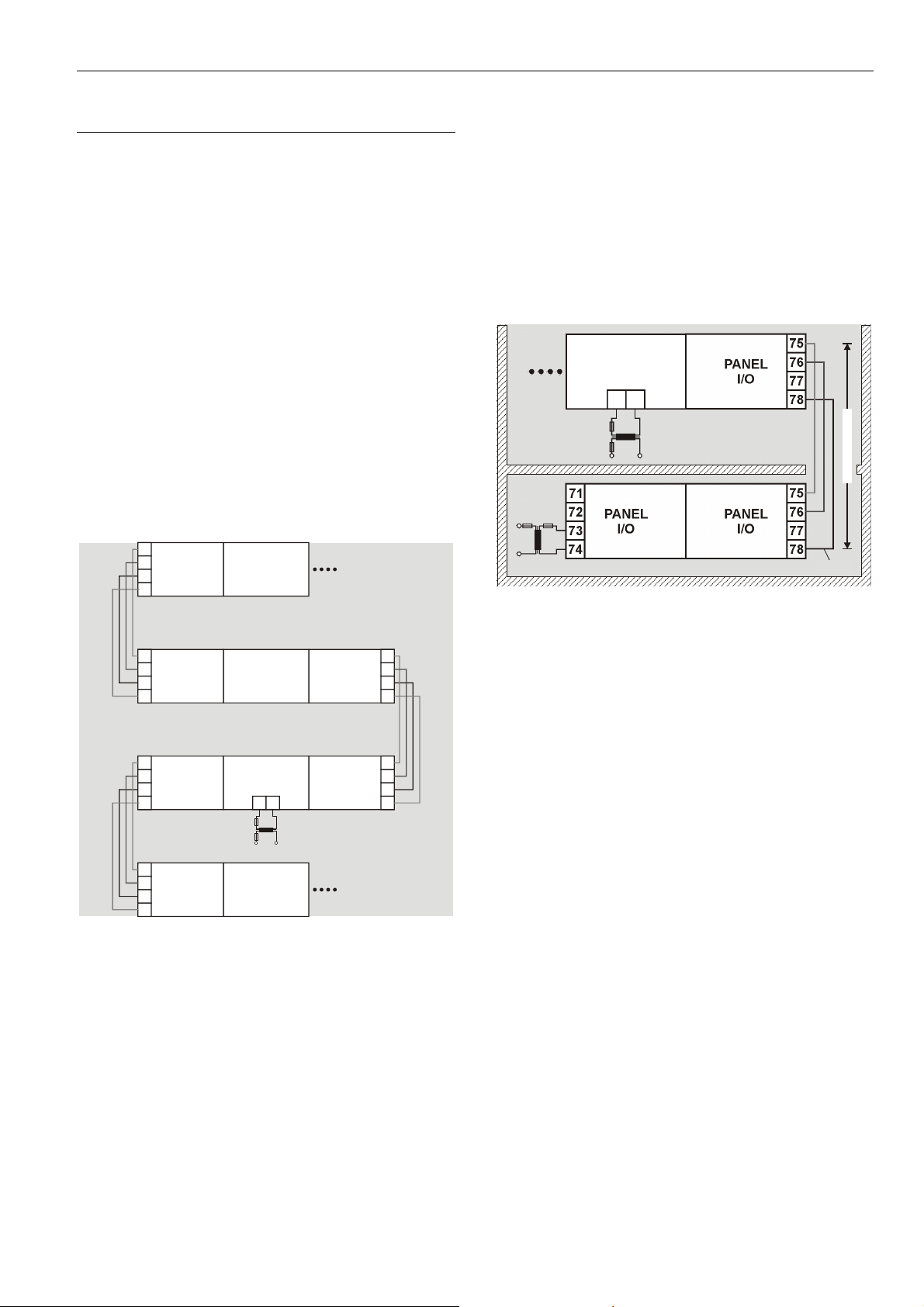
Panel Bus I/O Modules in Separate Rooms
In this scenario, communication and reference voltage
(24 V0) must be connected between the rooms.
► Connect the last module of room 1 to the first module of
room 2:
– Reference voltage
via power supply terminals 74 or 78
terminals 73 and 77 must not be connected
– Communication
via communication terminals 71, 72 or 75, 76
75
CPU
PANE L
I/O
1 2
71
PANEL
I/O
PANE L
I/O
74
Fig. 34 Wiring the Panel Bus I/O modules in separate
rooms
76
77
78
75
7672
7773
78
24 V0
MAX. 40 m
I/OI/O
I/O
75
76
77
78
75
76
77
78
71
72
I/O
73
74
71
72
I/O
73
74
71
72
I/O
73
74
CPU
1 2
I/O
Fig. 33 Wiring the power supply and the communication
lines to the I/O modules
Maximum Power Cable Length
The maximum length for power supply cable per side is 3 m.
This also includes the connection cables between the rails,
the lengths of the modules, and the cable from the
transformer.
Maximum Cable Length
The maximum cable length for connecting room 1 and
room 2 is 40 m.
25 EN1B-0375GE51 R0709
Page 26
Wiring and Setting Up the System Excel 800
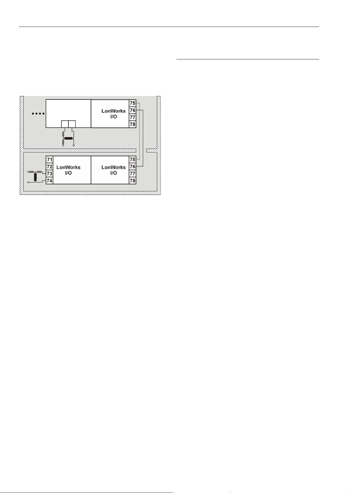
LonWorks Bus I/O Modules in Separate Rooms
In this scenario, only communication lines must be
connected between the rooms.
► Connect the last module of room 1 to the first module of
room 2:
– via communication terminals 71, 72 or 75, 76
75
CPU
1 2
71
LonWorks
I/O
74
Fig. 35 Wiring the LONWORKS Bus I/O modules in
separate rooms
LonWorks
I/O
LonWorks
I/O
76
77
78
75
7672
7773
78
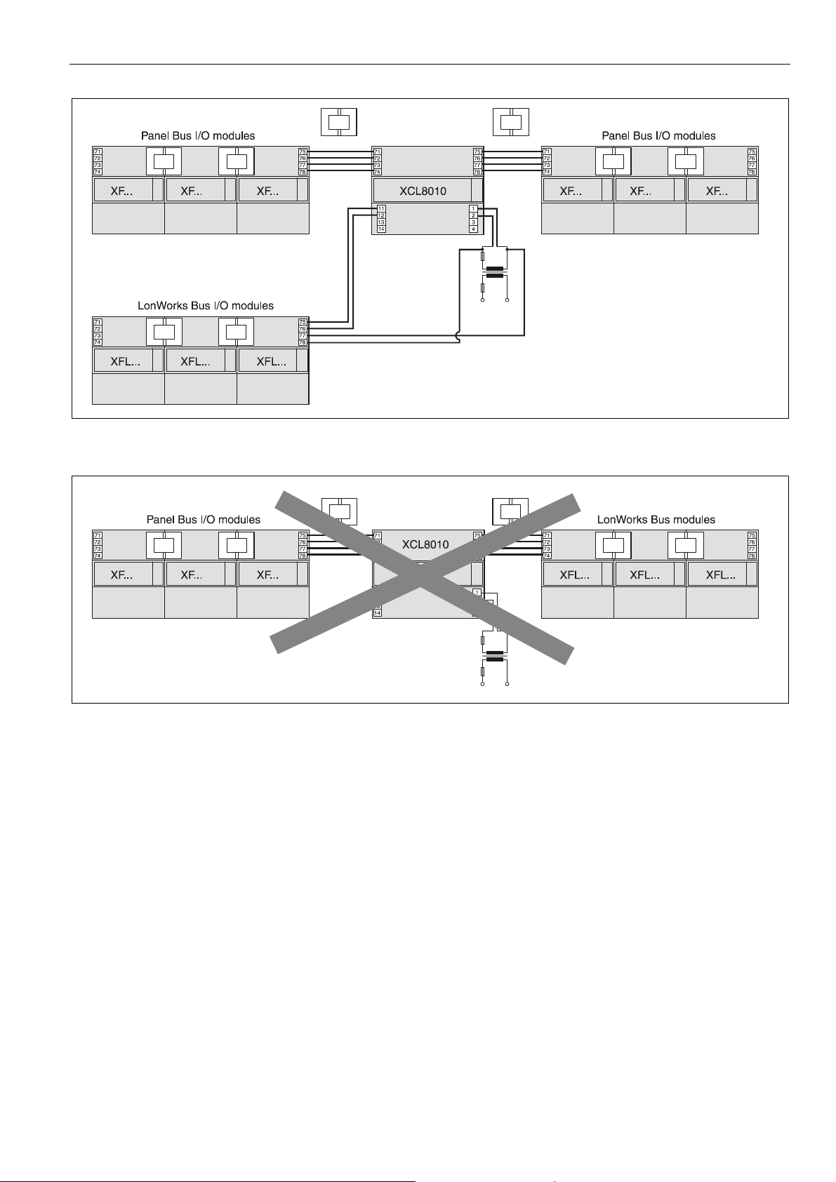
Connecting Panel Bus and LONWORKS Bus
Mixed Controller Systems
Connecting I/O Modules with Each Other
For connecting the I/O modules with each other, proceed as
described for single bus controller systems on page 24.
Connecting I/O Modules to the Controller
Panel Bus I/O Modules
► Connect communication terminals 71 …74 or 75… 78 of
Panel Bus I/O modules to communication terminals
71 …74 or 75… 78 of the controller module using either
– Bridge connectors
for flush mounting on a single DIN rail or
– Cables
for separate mounting,
e.g., on multiple rails, separate cabinets, etc.
L
ONWORKS Bus I/O Modules
► Connect communication terminals 71 … 74 or 75 … 78 of
L
ONWORKS Bus I/O modules to LONWORKS terminals
11 … 14 of the controller module using cables.
Maximum Cable Length
For maximum cable lengths and cable specifications of the
communication lines, see Table 18 and Table 19 on
page 13.
EN1B-0375GE51 R0709
26
Page 27
Excel 800 Wiring and Setting Up the System
Fig. 36 Mixed bus system – correct wiring
Fig. 37 Mixed bus system – incorrect wiring
27 EN1B-0375GE51 R0709
Page 28
Wiring and Setting Up the System Excel 800
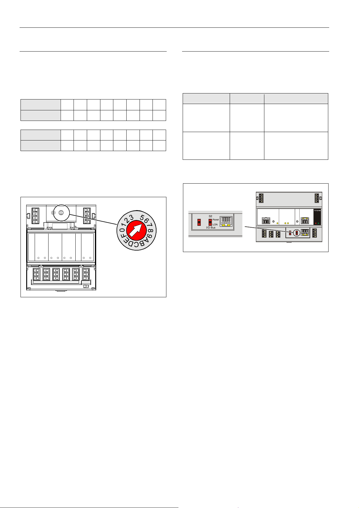
Setting Address of Panel Bus I/O Modules
During CARE engineering, each Panel Bus I/O module is
assigned its own unique address. For the sake of clarity for
maintenance personnel, it is recommended that you
address the Panel Bus I/O modules in ascending order
0 through F.
Hex switch
Address
Hex switch
Address
Table 24 HEX switch settings and addresses
► Use the rotary HEX switch to set the address to the one
already defined during CARE engineering.
0 1 2 3 4 5 6 7
01 02 03 04 05 06 07 08
8 9 A B C D E F
09 10 11 12 13 14 15 16
4
4
LOCK
Setting I/O Bus Switch
► Set the I/O Bus switch S2 of the XCL8010 Controller
Module depending on the modules connected to
terminals 71 … 78 and the desired communication as
follows:
Communication S2 setting Terminals
LONWORKS Bus
only
Panel Bus and
L
ONWORKS Bus
Table 25 I/O Bus switch settings
LON 71 … 74 L
75 … 78
11 … 14
ONWORKS Bus
LONWORKS Bus
LONWORKS Bus
Panel 71 … 74 Panel Bus
75 … 78 Panel Bus
11 … 14 L
ONWORKS Bus
Fig. 38 HEX switch location
Notes
If the HEX switch is changed, the Panel Bus I/O module
•
will revert to its default configuration.
•
With LONWORKS Bus I/O modules, the HEX switch is
without function.
Fig. 39 S2 I/O Bus switch
EN1B-0375GE51 R0709
28
Page 29

Excel 800 Wiring and Setting Up the System
Y
Y
Connecting Field Devices
Connecting Field Devices with Power Supply
Depending on the distance from the controller, field devices
can be supplied by the controller or need a separate
transformer, see Table 20 on page 13.
For fusing see section "Fusing Specifications" on page 10.
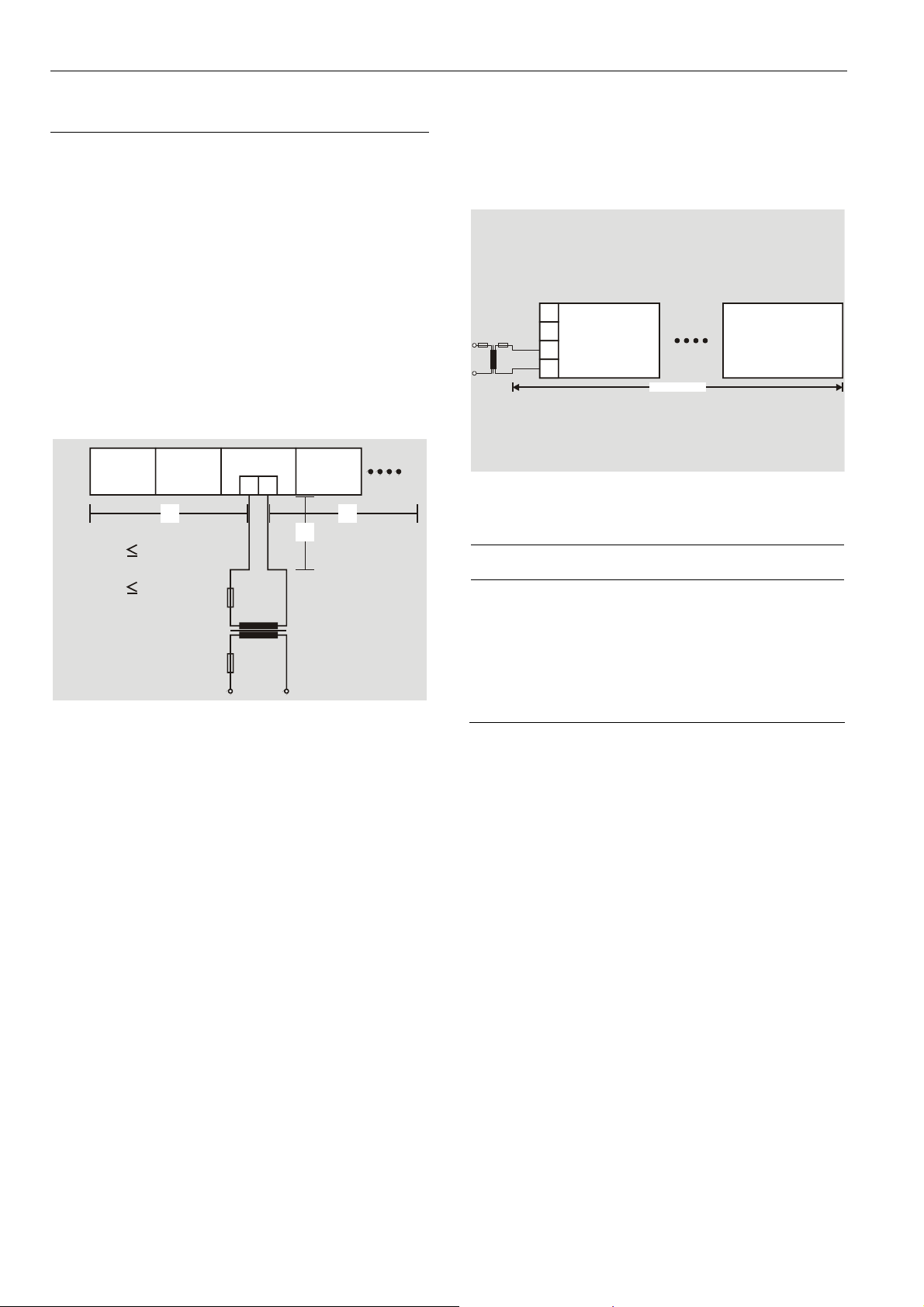
Example 1: Power Supply via Controller
•
24 V actuator connected to an analog output module
• Less than 100 m away from the controller
F2
XCL8010
F1
230 V~
24 V~
24 V0
1
2
Fig. 40 Power supply of field devices via I/O module
Example 2: Power Supply via Separate Transformer
24 V actuator connected to an analog output module
•
• 100 … 400 m away from the controller
822
24V
1...8
11...18
9
Y (0...10 Vdc)
max. 100 m
~
GND
Cabling Field Devices
Cable Routing
Route low-voltage signal and output cables separately from
mains cables.
Cable Minimum distance
Shielded 10 mm (0.4 in.)
Unshielded 100 mm (4 in.)
Table 26 Minimum distances to power mains cables
All low-voltage signal and output cables should be regarded
as communication circuits in accordance with VDE 0100
and VDE 0800 (or NEC or other equivalent).
Cable Shielding
• If the general guidelines for cable routing are observed, it
is not necessary to shield field device signal and power
supply cables.
• If, for whatever reason, the routing guidelines cannot be
observed, the field device signal and power supply
cables must be shielded.
– Shielding of cables leading to field devices must be
grounded only at the cabinet end.
– The shield must not be terminated at the XCL8010
Controller Module.
24 V0
24 V~
F2
230 V~
F1
24 V~
24 V0
XCL8010
1
2
822
1...8
11...18
Y (0...10 Vdc)
max. 400 m
Fig. 41 Power supply of field devices via a separate
transformer
230 V~
24V
GND
~
29 EN1B-0375GE51 R0709
Page 30

Wiring and Setting Up the System Excel 800
Commissioning I/O Modules
Commissioning Panel Bus I/O Modules
During CARE engineering, the HEX address of the Panel
I/O modules is defined.
Note
In the case of Panel Bus I/O modules, it is essential that the
HEX switch be set to the address assigned during CARE
engineering.
The XCL8010 Controller automatically commissions all
Panel Bus I/O modules.
Commissioning LONWORKS Bus I/O Modules
Commissioning is done using CARE.
Updating Software
The XCL8010 Controller software can be updated using
CARE.
Software with Panel Bus I/O Modules
The XCL8010 Controller automatically updates the software
of all Panel Bus I/O modules.
Software with LONWORKS Bus I/O Modules
The software of the LONWORKS I/O modules can be updated
using CARE or EXCELON.
EN1B-0375GE51 R0709
30
Page 31

Excel 800 Connecting to External Systems or Interfaces
Connecting to External Systems or Interfaces
WARNING
Risk of electric shock or equipment damage!
► Do not touch any live parts in the cabinet!
► Disconnect the power supply before making connections
to or removing connections from terminals of controller or
I/O modules.
► Do not reconnect the power supply until you have
completed installation.
► Observe the rules regarding electrostatic discharge.
Connecting via LONWORKS Bus
Via a LONWORKS Bus, an Excel 800 System can be
connected to other controller systems, to additional
L
ONWORKS Bus I/O modules, or to laptops.
LONWORKS Bus Termination
Depending upon the configuration, either 1 or 2 termination
modules are required for terminating a L
FTT devices on it.
The following 2 different L
ONWORKS termination units are
available for this purpose:
• 209541 LONWORKS Bus Termination Module and
• XAL-Term LONWORKS Connection and Termination
Module, which can be mounted on DIN rails and in fuse
boxes
ONWORKS bus with
Termination Examples
Brown
Orange
Yellow
Brown
Orange
Yellow
Fig. 42 Termination Module 209541 connections for a
doubly-terminated FTT network
Fig. 43 Termination Module 209541 connections for a
singly-terminated FTT network
Fig. 44 XAL-Term Connection and Termination Module
31 EN1B-0375GE51 R0709
Page 32

Connecting to External Systems or Interfaces Excel 800
Connecting via C-Bus
Via C-Bus an Excel 800 Controller can be connected to
other controller systems to form a network.
Connecting to the Controller
► Connect the C-Bus to the XCL8010 Controller Module as
follows:
– Input to C-Bus terminals 8 and 9
– Output to C-Bus terminals 5 and 6
– Do not connect the C-Bus to the cabinet earth or any
other earth ground points
Setting the C-Bus Termination Switch
► Set the C-Bus termination switch S1 appropriately.
Fig. 45 C-Bus termination switch S1
Switch
setting S1
9.6k all
76k mid Up to 76800 baud without bus termination
76k end Up to 76800 baud with bus termination
Table 27 XCL8010 C-Bus termination switch settings
How to Shield
In principle, data transmitting cables should be shielded in
case of RFI.
► On the controller side, connect the shield to terminals 7
and 10.
► On the side of the device, connect the shield to the
respective terminals.
Do not connect it to the cabinet ground or any other
ground points.
Baud rate
Up to 9600 baud (default setting)
Connecting HMIs or Laptops
HMIs, e.g., XI582 or XI882A, can be connected via the HMI
interface of the XCL8010 Controller Module. Laptops can be
connected via the HMI interface or via the L
interface of the XCL8010 Controller Module.
ONWORKS
Connecting the XI582 Operator Interface
► Connect the XI582 Operator Interface to the HMI
interface of the XCL8010
– the XW882 cable or
– the XW582 cable connected with an XW586 cable.
For mounting details, refer to the XI582 Installation
Instructions (Product Literature no.: EN2B-0126GE51).
For cable details, refer to section "Preconfigured Connection
Cables" on page 11.
Controller Module by means of
Connecting the XI882A Operator Interface
► Connect the XI882 Operator Interface to the HMI
interface of the XCL8010
– the XW882 cable or
– the XW586 cable connected with an XW585 cable.
For cable details, refer to section "Preconfigured Connection
Cables" on page 11.
Connecting Laptops (XL-Online/CARE)
► Connect a laptop (on which e.g., XL-Online or CARE has
been installed) to the HMI interface or to the L
interface of the XCL8010
– the XW885 cable or
– the XW585 cable connected with an XW586 Cable.
For cable details, refer to section "Preconfigured Connection
Cables" on page 11.
Controller Module by means of
Controller Module by means of
Connecting Modems
An Excel 800 System can be connected to a modem or an
ISDN terminal adapter via the Modem Interface of the
XCL8010
► Connect the RJ45 female connector of the XW586 cable
► Connect the 9-pin sub-D connector to the modem.
For cable details, refer to section "Preconfigured Connection
Cables" on page 11.
Refer to Appendix 2 for details regarding remote
communication.
Controller Module by means of the XW586 cable.
to the modem interface of the XCL8010
Controller.
ONWORKS
EN1B-0375GE51 R0709
32
Page 33

Excel 800 Description of the XCL8010 Controller Module
Description of the XCL8010 Controller Module
Overview
PC or HMI
Excelon
LonWorks Bus
LONW
ORKS
I/O modules
/
Panel Bus
Modem
L
ONWORKS
XL12
Fig. 46 Connections to the XCL8010 Controller
Fig. 47 XCL8010 Controller Module front details
Bus
C-Bus
Legend
1 Power supply for I/O modules
2 I/O Bus communication terminals
3 L
ONWORKS interface
4 L
ONWORKS service button
5 L
ONWORKS service LED
6 C-Bus Tx LED
7 C-Bus Rx LED
8 Reset button
9 HMI interface and LEDs
10 Alarm LED
11 Power LED
12 Power supply terminals
13 Alarm/watchdog outputs
14 Modem interface and LEDs
15 S2 I/O Bus switch
16 S1 C-Bus termination switch
17 C-Bus terminals
18 L
ONWORKS terminals
XL500
33 EN1B-0375GE51 R0709
Page 34

Description of the XCL8010 Controller Module Excel 800
XCL8010 Terminals
COM
71
A
COM
72
B
24
73 77
V
~
24
74
V
~
0
8 7654 32 1
LON
11
1
12
13
14
LON
LON
LON
2
1
2
85C+ C+
C- C-9 6
SHIELD SHIELD
10 7
*WATCHDOG
RELAY
Fig. 48 Terminal assignment and internal connections of
the XCL8010
Controller Module
Terminal
71, 75 COM a
72, 76 COM b
Signal Comment
2-wire communication bus
(LON/Panel Bus)
2-wire communication bus
(LON/Panel Bus)
73, 77 24 V~ Power supply for I/O modules
74, 78 24 V~0 Power supply for I/O modules
1 24 V~ Power supply from transformer
2 24 V~0 Power supply from transformer
3 24 V~0 Alarm/watchdog output
4 NC Alarm/watchdog output
5, 8 C+ C-Bus
6, 9 C- C-Bus
7, 10 Shield C-Bus shield
11, 12 LON LONWORKS IN
13, 14 LON LONWORKS OUT
COM
75
A
COM
76
B
24
V
~
24
78
V
~
0
1
2
V
3
V
*
4
NC
Features
LONWORKS Interface and Terminals
The XCL8010 Controller Module features
• An RJ45 socket serving as an interface
to connect laptops to the L
• LONWORKS terminals 11, 12, 13, and 14
to connect L
ONWORKS devices to the XCL8010 Controller or other
L
L
24
V
~
24
~
0
24
~
0
ONWORKS controllers.
ONWORKS Bus I/O modules or other
Fig. 49 LONWORKS interface and LONWORKS terminals
LONWORKS Interface Signals on RJ45 Socket
Pin Signal type
1 Connection to LONWORKS Bus
2 Connection to LONWORKS Bus
3 … 8 Not used
Table 29 Signals of LONWORKS interface
LONWORKS Service LED and Button
The XCL8010 Controller Module is equipped with a
L
ONWORKS service button and corresponding LONWORKS
Service LED (status: yellow/OFF).
ONWORKS Bus
Table 28 Description of XCL8010 terminals
EN1B-0375GE51 R0709
LON
1
2
Fig. 50 LONWORKS service button (1) and service LED (2)
See also section "Troubleshooting" on page 73.
34
Page 35

Excel 800 Description of the XCL8010 Controller Module
C-Bus Tx LED and Rx LED
The XCL8010 Controller Module is equipped with a Tx LED
(status: yellow/OFF) and an Rx LED (status: yellow/OFF).
C-Bus
1
2
Fig. 51 C-Bus Tx LED (1) and Rx LED (2)
C-Bus LEDs
Tx (1)
flickering
Rx (2)
flickering
Table 30 Controller C-Bus LEDs
The controller is sending data onto the
C-Bus
The controller is receiving data from the
C-Bus
HMI Interface
The controller module is equipped with an HMI Interface for
the connection of HMIs, e.g., the XI582 or the XI882A, or a
laptop (with XL-Online/CARE).
Fig. 53 HMI interface, Tx LED (1) and Rx LED (2)
HMI interface LEDs on RJ45 socket
Tx (1)
flickering
Rx (2)
flickering
The controller is transmitting data to the HMI
The controller is receiving data from the HMI
Reset Button
The XCL8010 Controller Module is equipped with a reset
button.
RESET
1
Fig. 52 Reset button (1)
Pushing the reset button (1), e.g. using a paperclip, will
cause the XCL8010
Note
In the event of a reset, all non-volatile memory contents are
permanently deleted, though the clock will not be set to
zero.
In order to avoid problems, we therefore recommend that
you always save your application changes (e.g., time
program changes) to FLASH memory.
Controller Module to reset.
Table 31 HMI interface LEDs
HMI interface Signals on RJ45 socket
Pin Signal type
1 -
2 Receive
3 Transmit
4 -
5 Signal ground
6 -
7 5 V
8 -
Table 32 Signals of the HMI interface
NOTICE
Equipment damage!
► Make sure that the controller is not connected to earth
ground.
► If nonetheless earth grounding is required, make sure
that only terminal 2 is connected to earth ground.
Terminal 1 must not be connected to earth ground. See
also Appendix 1.
35 EN1B-0375GE51 R0709
Page 36

Description of the XCL8010 Controller Module Excel 800
Alarm and Power LEDs
The XCL8010 Controller Module is equipped with an alarm
LED and a power LED.
Fig. 54 Alarm LED (1) and power LED (2)
Alarm LED (1, red)
Off
On
Flashing The watchdog alarm output has not yet been
Normal operation
Watchdog alarm output is powered
• The controller has encountered a
hardware problem
• The application has a fault
• The controller has been powered up
without an application or the operator has
manually stopped the application,
e.g., using XL-Online.
In this case, the LED will light up
13 minutes after power-up without
application
powered, although the controller has
encountered a problem.
The controller performs a warm start.
If problem persists, the LED will become lit
constantly, see above.
See section "Troubleshooting" on page 73.
Power LED (2, green)
On
Flashing One or more of the internal voltage
Is extinguished
briefly
Table 34 Controller power LED
Watchdog
Watchdog status
Status Signal on terminal 4
Failure (= alarm) 24 V
Normal operation 0 V
Table 35 Watchdog status 4
Permissible Load of Normally Closed Contact
(Terminal 4)
Max. load
Per normally
closed
contact
(terminal 4)
Table 36 Permissible load of terminal 4
Normal operation
supplies are outside of the permissible
ranges.
The controller stops operation.
► Check wiring or see section
"Troubleshooting" on page 73.
•
The operator has activated the reset
button
• The controller is performing a warm
start
19…29 VAC
current at cos φ ≥ 0.95: 0.5 A,
current at cos φ ≥ 0.6: 0.5 A
19…29 VDC
0.5 A resistive or inductive
Min.
current
10 mA
Table 33 Controller alarm LED
EN1B-0375GE51 R0709
36
Page 37

Excel 800 Description of the XCL8010 Controller Module
Modem Interface
The controller module is equipped with a modem interface
for the connection of a modem or an ISDN terminal adapter.
Fig. 55 Modem interface, Tx LED (1) and Rx LED (2)
Modem LEDs on RJ45 socket
Tx (1) flickering The controller is transmitting data to the
HMI, e.g., XI582 or XI882A
Rx (2) flickering The controller is receiving data from the
HMI
Table 37 HMI interface LEDs
Modem Signals on RJ45 socket
Pin Signal type
1 Carrier detect
2 Receive
3 Transmit
I/O Bus Switch S2
The XCL8010 Controller Module features a 2-position I/O
Bus switch S2.
I/O Bus switch S2 must be set in accordance with the kind
of I/O modules connected to communication terminals
71, 72 and 75, 76 of the controller module.
Terminals 71, 72 and 75, 76 must be all connected either to
Panel Bus I/O modules or to L
The
default setting is Panel.
Fig. 56 I/O Bus switch S2
Communication S2 setting
LONWORKS Bus only LON
Panel Bus and LONWORKS Bus
ONWORKS BUS modules connected to
L
terminals 11 …. 14 of the controller
Panel Bus connected to terminals 71, 72
or 75, 76 of the controller
Table 39 I/O Bus switch settings
ONWORKS Bus I/O modules.
Panel
Panel
4 Data terminal ready
5 Signal ground
6 -
7 5 V
8 Clear to send
Table 38 Signals of the modem interface
Communication Speed
Default setting: 9600 baud
The communication speed can be set to as high as
38.4 Kbaud, e.g., using the HMI (XI852 or XI882A) or a
Laptop with XL-Online, see Appendix 2.
37 EN1B-0375GE51 R0709
Page 38

Description of the XCL8010 Controller Module Excel 800
C-Bus Termination Switch S1
The XCL8010 Controller Module features a 3-position C-Bus
termination switch S1.
This switch must be set in accordance with the given C-Bus
configuration.
Fig. 57 C-Bus termination switch
Switch
setting S1
9.6k all
76k mid Up to 76800 baud without bus termination
Baud rate
Up to 9600 baud (default setting)
76k end
Table 40 XCL8010 C-Bus termination switch S1 settings
Up to 76800 baud with bus termination
controller at the end of the C-Bus
Memory
Memory Size Usage
SRAM 512 KB
Flash 2 MB
EPROM 128 KB For bootstrap loader
Table 41 XCL8010 memory
Note
The XCL8010
RAM (data and realtime clocktime) is buffered for 3 days by
a super capacitor.
Controller Module does not contain a battery.
For controller application,
modem trend and firmware
RACL application: 128 KB
Total application: 192 KB
Firmware (1 MB) and
application (1 MB) storage
EN1B-0375GE51 R0709
38
Page 39

Excel 800 Description of the I/O Modules
Description of the I/O Modules
Common Features
Switches located on the Terminal Socket
Feature Function
Service
button S1
(pluggable I/O
modules,
only)
Hex switch
S2
LEDs located on the I/O Module
Feature Function
Service LED
(yellow)
Power LED
(green)
For the location of these elements, see figures of the
relative modules.
• LED test, see section "Troubleshooting"
on page 73
• LONWORKS service button functionality
for L
ONWORKS Bus I/O modules
• Module addressing for Panel Bus
I/O modules
• Service information, see section
"Troubleshooting" on page 73
• Information on power supply, see
section "Troubleshooting" on page 73
Analog Input Modules
Types of Analog Input Modules, Terminal Socket
Type Description Housing
XF821
XFL821
XS821-822
XSU821-822
Table 42 Excel 800 Analog Input Modules
Panel Bus analog input
module
ONWORKS Bus analog input
L
module
Terminal socket Light-gray
Features
• 8 analog inputs
• Sensor-break and short-circuit detection, see section
"Troubleshooting" on page 73.
Light-gray
Dark-gray
Fig. 58 XF821 Analog Input Module with terminal socket
Legend
1 Service button S1
2 Hex switch S2
3 Service LED
4 Power LED
Functionality of service LED and power LED: see Table 77
to Table 79 on page 77 and following.
39 EN1B-0375GE51 R0709
Page 40

Description of the I/O Modules Excel 800
Terminals
COM
71
A
COM
72
B
24
73 77
V
~
24
74
V
~
0
V
AUXVAUX
21
22
109
AI3
AI1
AI2
AI2
1 234
GNDGNDGND GND GND GND GND GND GND GND
11
121314
AI5AI6
AI4
5
15 161718 25 26
AI8
AI7
6
7 8
Fig. 59 Terminal assignment and internal connections of
analog input modules
Terminal
71, 75 COM a
72, 76 COM b
SIGNAL Comment
2-wire communication bus
(LON/Panel Bus)
2-wire communication bus
(LON/Panel Bus)
73, 77 24 V~ Power supply
74, 78 24 V~0 Power supply
1…8 AI1 … AI8 Analog inputs 1…8
9…18 GND
21, 22
10 VDC/
5 mA, ±2%
25, 26
Ground. All grounds are internally
connected internally to each other.
Auxiliary voltage signal (used e.g. for
supplying setpoint potentiometers)
Shield connection (functional earth),
internally connected to the DIN rail
Table 43 Description of analog input module terminals
Notes
• Shield connection to be used for shielded I/O cables only.
It is not allowed to connect a L
L
ONWORKS requires a resistor and a capacitor.
ONWORKS shield, since
• If additional shield terminals are needed, the
XS814 Auxiliary Terminal Package can be installed.
COM
COM
V
V
75
A
76
B
24
~
24
78
~
0
Technical Data
Input
Protection Protected against failure voltage (24 VAC,
Resolution
Accuracy
Table 44 Analog input modules data
Range
-50...-20 °C
(-58...-4 °F)
-20…0 °C
(-4…+32 °F)
0...30 °C
(32…86 °F)
30...70 °C
(86...158 °F)
70...100 °C
(158...212 °F)
100...130 °C
(212...266 °F)
130...150 °C
(266...302 °F)
150…400 °C
(302…752
°F)
(1
Balco specified for -30 °C … +120 °C, only
(2
NTC10kΩ specified for -30 °C … +100 °C, only
(3
NI1000TK5000 specified for -30 °C … +130 °C, only
• 0(2) ... 10 VDC
• 0(4) ... 20 mA
(via external 499 Ω/0.25% resistor
• NTC20kΩ (-50…+150 °C; default)
• PT1000-1 (-50…+150 °C)
• PT1000-2 (0…+400 °C)
• PT3000 (-50…+150 °C)
• BALCO500 (-30…+120 °C)
• NTC10kΩ (-30…+100 °C)
• NI1000TK5000 (-30…+130 °C)
• Slow binary input
40 VDC)
16-bit resolution
±75 mV (0 ... 10 V), without sensor
PT1000-1
≤ 1.2 K – ≤ 1.2 K ≤ 1.2 K ≤ 5.0 K ≤ 5.0 K ≤ 1.2 K
≤ 0.7 K – ≤ 0.7 K ≤ 0.7 K ≤ 1.0 K ≤ 1.0 K ≤ 0.7 K
≤ 0.5 K ≤ 0.5 K ≤ 0.5 K ≤ 0.5 K ≤ 0.3 K ≤ 0.5 K ≤ 0.5 K
≤ 0.7 K ≤ 0.7 K ≤ 0.7 K ≤ 0.7 K ≤ 0.5 K ≤ 0.5 K ≤ 0.7 K
≤ 1.2 K ≤ 1.2 K ≤ 1.2 K ≤ 1.2 K ≤ 1.0 K ≤ 1.0 K ≤ 1.2 K
≤ 1.2 K ≤ 1.2 K ≤ 1.2 K ≤ 1.2 K ≤ 3.0 K – ≤ 1.2 K
≤ 1.2 K ≤ 1.2 K – ≤ 1.2 K ≤ 5.5 K – –
– ≤ 1.2 K – – – – –
(3
(1
PT1000-2
Balco500
PT3000
NTC20kΩ
(2
(default)
NTC10kΩ
NI1000TK5000
EN1B-0375GE51 R0709
Table 45 Accuracy of analog input sensors
Note
The accuracy of the sensor itself is not included in this table.
40
Page 41

Excel 800 Description of the I/O Modules
Internal Impedance when Connecting Sensors
Fig. 60 Analog input low impedance (input circuit for
PT1000, Balco500, PT3000, NI1000TK5000,
slow binary input)
Fig. 61 Analog input high impedance (input circuit for
voltage input for active sensors)
Fig. 62 Analog input impedance setpoint (input circuit for
NTC10kΩ, NTC20kΩ, wall module setpoint)
41 EN1B-0375GE51 R0709
Page 42

Description of the I/O Modules Excel 800
Connection Examples
Active Sensor and Potentiometer
Fig. 63 Analog input module, wiring example 1
For fusing specifications see section "Fusing Specifications" on page 10.
EN1B-0375GE51 R0709
42
Page 43

Excel 800 Description of the I/O Modules
Passive Sensor and 0 (4) … 20 mA Signal
Fig. 64 Analog input module, wiring example 2
43 EN1B-0375GE51 R0709
Page 44

Description of the I/O Modules Excel 800
Analog Output Modules
Types of Analog Output Modules, Terminal Socket
Type Description Housing
XF822
Panel Bus analog output
module
XFR822
Panel Bus analog output
module with manual overrides
ONWORKS Bus analog output
XFL822
L
module
ONWORKS Bus analog output
XFLR822
L
module with manual overrides
XS821-22
Terminal socket Light-gray
XSU821-22
Table 46 Excel 800 analog output modules
Features
• 8 analog outputs;
can also be configured per output as binary outputs
(0 … 10 V, 2 … 10 V, ON/OFF, or floating)
• Corresponding status LEDs (red)
• …R822: 8 manual overrides, see figure below
Light-gray
Light-gray
Dark-gray
Dark-gray
In the event of communication problems, the analog outputs
will move to the safety positions you have configured in
CARE, see analog output point description in the CARE –
User Guide, EN2B-0182GE51 / 74-5587.
Terminals
COM
71
A
COM
72
B
24
73 77
V
~
24
74
V
~
0
NC NC
21
AO1AO2 AO3AO4AO5AO6 AO7AO8
1 234
22
GNDGNDGND GND GND GND GND GND GND GND
109
11
121314
5
6
7 8
15 161718 25 26
Fig. 66 Terminal assignment and internal connections of
the analog output modules
Terminal
71, 75 COM a
72, 76 COM b
Signal COMMENT
2-wire communication bus
(LON/Panel Bus)
2-wire communication bus
(LON/Panel Bus)
73, 77 24 V~ Power supply
74, 78 24 V~0 Power supply
1…8 AO1…AO8 Analog outputs 1…8
9…18 GND
Ground. All grounds are internally
connected to each other.
21, 22 N.C. Do not use!
25, 26
Shield connection (functional earth),
internally connected to the DIN rail
COM
COM
24
V
24
V
75
A
76
B
~
78
~
0
Fig. 65 XF822 Analog Output Module with terminal
socket
Legend
1 Service button S1
2 Hex switch S2
3 Manual overrides
4 Status LEDs
5 Service LED
6 Power LED
Functionality of service LED and power LED: see Table 77
to Table 79 on page 77 and following.
EN1B-0375GE51 R0709
Table 47 Description of the analog output module terminals
Notes
•
Shield connection to be used for shielded I/O cables only.
It is not allowed to connect a L
L
ONWORKS requires a resistor and a capacitor.
•
If additional shield terminals are needed, the
ONWORKS shield, since
XS814 Auxiliary Terminal Package can be installed.
44
Page 45

Excel 800 Description of the I/O Modules
Technical Data
Voltage rating
Current rating
Resolution
Accuracy
Zero output voltage
Protection
Feedback signal
Table 48 Analog output modules data
0(2)…11 V (default)
max. ±1 mA
8 bit
±150 mV
< 200 mV
Short-circuit protected;
protected against failure
voltage (24 VAC, 40 VDC)
automatic/manual mode and
output value
Status LED Behavior
Automatic mode Brightness is proportional to
the commanded output signal
Override mode
Table 49 Analog output status LED behavior
Flashes
Status LEDs with Manual Overrides
5
12
Fig. 67. Manual overrides (rotary knobs)
The XFR822/XFLR822 Analog Output Modules are
equipped with manual overrides: one for each analog
output. These rotary knobs can be manually set to either
"AUTO" or "0…100%" (infinitely adjustable).
4
3
678
Honeywell
0!100
AUTO
NOTICE
Damage to the electronic module!
► Do not use a tool to adjust the rotary knobs.
► Do not use excessive force. Adjust only by hand.
Manual Override in the AUTO Position
When a manual override of the XFR822/XFLR822 is set to
AUTO, and the corresponding analog output has been
configured, the following applies:
• If the LONWORKS network is functioning properly, the
output voltage of the analog output will be as
commanded.
• If the LONWORKS network is not functioning properly, the
output voltage of the analog output will be the safety
position value.
• The brightness of the status LED (red) of the analog
output will be proportional to the commanded output
signal.
When a manual override of the XFR822/XFLR822 is set to
AUTO, and the corresponding analog output has
configured, the following applies:
• Regardless as to whether the LONWORKS network is
functioning properly or not, the output voltage of the
analog output will be 0 V (values from the L
Bus will be ignored, and there will be no heartbeat or
safety position).
• The feedback signal on the LONWORKS network
nvoAoActPosnFb[ ] will have a value of 0% and a state
of 0.
• The analog output status LED will be unlit.
Manual Override in the Override Position (0…100%)
When a manual override of the XFR822/XFLR822 is set to
0…100%, and the corresponding analog output has been
configured, the following applies:
• The output voltage of the analog output will be 0…10 V
(direct) or 10…0 V (reverse).
• The feedback signal on the LONWORKS network
nvoAoActPosnFb[ ] will have a value of 0…100% and a
state of -1.
• The status LED (red) of the analog output will flash to
indicate “manual override.”
When a manual override of the XFR822/XFLR822 is set to
0…100%, and the corresponding analog output has
been configured, the following applies:
• The output voltage of the analog output will be 0…10 V.
• The feedback signal on the LONWORKS network
nvoAoActPosnFb[ ] will have a value of 0…100% and a
state of -1.
• The status LED (red) of the analog output will flash to
indicate “manual override.”
Analog Outputs Configured as Binary Outputs
Using CARE, the analog outputs can be configured
individually as binary outputs. The voltage output is then 0 V
or 10 V, depending upon the signal from the controller.
not been
ONWORKS
not
45 EN1B-0375GE51 R0709
Page 46

Description of the I/O Modules Excel 800
Connection Example
Fig. 68 Analog output connection example
For fusing specifications see section "Fusing Specifications" on page 10.
EN1B-0375GE51 R0709
46
Page 47

Excel 800 Description of the I/O Modules
Synchronization Behavior of Analog Output
Module Configured as Floating Output
In order to regularly update the real actuator position with
the calculated position and thus ensure that the actuator
definitely reaches its end position, a synchronization
process is performed by the analog output module.
During the synchronization process, the analog output
module will continue running for the configured runtime
once it reaches the calculated end position.
This updating (synchronization) is performed:
• If the calculated position of the actuator
< lower synchronization threshold (2%)
= synchronization towards 0%
• If the calculated position of the actuator
> upper synchronization threshold (98%)
= synchronization towards 100%
• Following any power-up or any reset
Fig. 69 Connection example with Relay Module MCD 3
• The relay module facilitates the control of peripheral devices with high load via the analog outputs.
• Input terminal 17 controls of MCD3 controls changeover contact K3.
• Relay terminal 18 of MCD3 controls the N.O. contacts (floating outputs) K1, K2.
For fusing specifications, see section "Fusing Specifications" on page 10.
47 EN1B-0375GE51 R0709
Page 48

Description of the I/O Modules Excel 800
Fig. 70 Connection example with Relay Module MCE 3
The relay module facilitates the control of peripheral devices with high load via the analog outputs.
• Input terminal 16 of MCE3 controls the N.O. contact K3.
• Input terminal 17 of MCE3 controls the changeover contact K2.
• Input terminal 18 of MCE3 controls the changeover contact K1.
For fusing specifications, see section "Fusing Specifications" on page 10.
EN1B-0375GE51 R0709
48
Page 49

Excel 800 Description of the I/O Modules
Binary Input Modules
Types of Binary Input Modules, Terminal Socket
Type Description Housing
XF823 Panel Bus binary input module Light-gray
L
XFL823
XS823
XSU823
Table 50 Excel 800 Binary Input Modules
Features
• 12 binary inputs
• 12 configurable status LEDs (green/red, yellow/OFF)
• Binary inputs can be used as
– Static digital inputs as dry-contacts (default)
– Fast totalizers (up to 20 Hz)
ONWORKS Bus binary input
Dark-gray
module
Terminal socket Light-gray
Terminals
COM
71
A
COM
72
B
24
73 77
V
~
24
74
V
~
0
BI10
BI3
BI1 BI2
1 234
131415 161718 19 20
BI5 BI6
BI4
5
GNDGNDGND GND GND GND GND GND GND GNDGND GND
BI8 BI9
BI7
6
7 8
BI11BI12
109
11
12
21 222324
Fig. 72 Terminal assignment and internal connections of
binary input modules
Terminal
71, 75 COM a
72, 76 COM b
Signal COMMENT
2-wire communication bus
(LON/Panel Bus)
2-wire communication bus
(LON/Panel Bus)
73, 77 24 V~ Power supply
74, 78 24 V~0 Power supply
1…12 BI1…BI12 Binary inputs 1…12
13…24 GND
25, 26
Ground. All grounds are internally
connected to each other.
Shield connection (functional earth),
internally connected to the DIN rail.
COM
COM
V
25 26
75
A
76
B
24
V
~
24
78
~
0
Table 51 Description of binary input module terminals
Notes
• Shield connection to be used for shielded I/O cables only.
Fig. 71 XF823 Binary Input Module with terminal socket
Legend
1 Service button S1
It is not allowed to connect a L
ONWORKS requires a resistor and capacitor.
L
• If additional shield terminals are needed, the
XS814 Auxiliary Terminal Package can be installed.
ONWORKS shield, since
2 Hex switch S2
3 Status LEDs
4 Service LED
5 Power LED
Functionality of service LED and power LED: see Table 77
to Table 79 on page 77 and following.
49 EN1B-0375GE51 R0709
Page 50

Description of the I/O Modules Excel 800
Technical Data
Input type
Current rating (closed
input)
Open contact voltage
Protection
Dry-contact or open collector
2 mA
16…22 VDC
Protected against failure
voltage (24 VAC, 40 VDC)
Status LED Behavior
Using CARE, each of the twelve status LEDs can be
configured individually for use as either alarm LEDs
(red/green) or as status LEDs (yellow/OFF [default]).
Given a logical state of "ON," the status LED will be lit
(yellow or red).
Configuration as Fast Totalizer
Using CARE, the binary inputs can be configured as fast
totalizers for operation in conjunction with devices equipped
with an open collector output.
Frequency
Pulse ON
Pulse OFF
Bounce
Table 52 Binary inputs used as fast totalizers
max. 20 Hz
min. 25 ms
min. 25 ms
max. 5 ms
Fig. 73 Configuration of binary input as fast totalizer
EN1B-0375GE51 R0709
50
Page 51

Excel 800 Description of the I/O Modules
Connection Example
Fig. 74 XF823 connection examples
For fusing specifications, see section "Fusing Specifications" on page 10.
51 EN1B-0375GE51 R0709
Page 52

Description of the I/O Modules Excel 800
Relay Output Modules
Types of Relay Output Modules, Terminal Socket
Type Description Housing
XF824 Panel Bus relay output module Light-gray
XFR824
XFL824
XFLR824
XS824-25
XSU824-25
Table 53 Excel 800 Relay Output Modules
Features
• 6 relays (changeover contacts), arranged in two blocks
• …R824: 6 manual overrides
• Low and line voltage allowed, see WARNING.
Panel Bus relay output module
with manual overrides
L
ONWORKS Bus relay output
module
L
ONWORKS Bus relay output
module with manual overrides
Terminal socket; can be fitted
with long (red) cross connector
(incl. in scope of the delivery)
Light-gray
Dark-gray
Dark-gray
Light-gray
In the event of communication problems, the relay outputs
will move to the safety positions you have configured in
CARE, see relay output point description in the CARE –
User Guide, EN2B-0182GE51 / 74-5587.
WARNING
Risk of electric shock or equipment damage!
Low voltage and line voltage must not
the same relay block.
► Wire low voltage e.g., to relay block 1 and line voltage to
relay block 2 or vice versa. In this case, the short cross
connectors must be used, see Table 5 on page 7.
be wired within
NOTICE
Risk of malfunction!
Cross connectors may only be used if the same voltage
is used on all relays they connect.
► Do not use a cross connector if different voltages are
used on the relays.
E.g., use a short cross connector for relay block 1 with
line voltage and no cross connector for relay block 2 with
12 V low voltage for relay 4 and 24 V low voltage for
relays 5 and 6.
Fig. 75 XF824 Relay Output Module with terminal socket
Legend
1 Service button S1
2 Hex switch S2
3 Manual overrides
4 Status LEDs
5 Service LED
6 Power LED
Functionality of service LED and power LED: see Table 77
to Table 79 on page 77 and following.
EN1B-0375GE51 R0709
52
Page 53

Excel 800 Description of the I/O Modules
Terminals
COM
71
A
COM
72
B
24
73 77
~
V
24
74 78
V
~
0
RELAY BLOCK 1 RELAY BLOCK 2
NO NONO NONO NO
11 4121 5131 61
12 4222 5232 62
NC NCNC NCNC NC
COM COMCOM COMCOM COM
13 4323 5333 63
CROSS CONNECTOR (REMOVABLE)
Fig. 76 Terminal assignment and internal connections of
relay output modules
Terminal Signal Comment
71, 75
72, 76
73, 77
74, 78
11
12
13
21
22
23
31
RELAY BLOCK 1
32
33
41
42
43
51
52
53
61
RELAY BLOCK 2
62
63
25
COM a
COM b
24 V~
24 V~0
REL1 N.O.
REL1 N.C.
R1 COM
REL2 N.O.
REL2 N.C.
R2 COM
REL3 N.O.
REL3 N.C.
R3 COM
REL4 N.O.
REL4 N.C.
R4 COM
REL5 N.O.
REL5 N.C.
R5 COM
REL6 N.O.
REL6 N.C.
R6 COM
2-wire communication bus
(LON/Panel Bus)
2-wire communication bus
(LON/Panel Bus)
Power supply
Power supply
Relay 1 N.O. contact
Relay 1 N.C. contact
relay 1 common contact
Relay 2 N.O. contact
Relay 2 N.C. contact
Relay 2 common contact
Relay 3 N.O. contact
Relay 3 N.C. contact
Relay 3 common contact
Relay 4 N.O. contact
Relay 4 N.C. contact
Relay 4 common contact
Relay 5 N.O. contact
Relay 5 N.C. contact
Relay 5 common contact
Relay 6 N.O. contact
Relay 6 N.C. contact
Relay 6 common contact
Shield connection (functional earth),
internally connected to the DIN rail
Table 54 Description of relay output module terminals
COM
COM
24
V
24
V
75
A
76
B
~
~
0
25
Permissible Loads
Max. load Min. load
Per relay
output
module (total)
19…250 VAC
current at cos φ ≥ 0.6: 12 A
1…29 VDC
12 A resistive, 3 A inductive
Per normally
open contact
19…250 VAC
current at cos φ ≥ 0.6: 4 A
1…29 VDC
4 A resistive, 1 A inductive
Per normally
closed
contact
19…250 VAC
current at cos φ ≥ 0.95: 2 A,
current at cos φ ≥ 0.6: 1 A
1…29 VDC
4 A resistive, 1 A inductive
Table 55 Permissible loads of relay output modules
Notes
• In the case of voltages above 30 VAC/DC and if inductive
components are to be connected to relays switching
more often than once every 2 minutes, these components must be prevented from causing harmful
interference to radio or television reception (conformance
with EN 55014).
• Max. voltage for UL 864-compliant applications is 24 V.
Status LED Behavior
Relay output
Mode LED
N.O.*
(direct)
Automatic mode, logical
ON ON OFF
state “ON”
Automatic mode, logical
OFF OFF ON
state “OFF”
Override mode (setting “0”) Flashes OFF ON
Override mode (setting “1”) Flashes ON OFF
*As configured using CARE.
Table 56 Relay output status LED behavior
Status LEDs with Manual Overrides
5
12
4
3
6
–
50 mW
50 mW
N.C.*
(reverse)
Honeywell
--1
--0
--AUTO
!
Fig. 77 Manual overrides (toggle switches)
The …R824 Relay Output Modules are equipped with
manual overrides: one for each relay output. These toggle
switches can be manually set to either "AUTO" or "0" or "1".
53 EN1B-0375GE51 R0709
Page 54

Description of the I/O Modules Excel 800
Manual Override in the AUTO Position
When a manual override of the …R824 Relay Output
Module is set to the “AUTO” position, and the corresponding
relay output has been configured, the following applies:
• If the LONWORKS network is functioning properly, the
logical status of the relay output will be “AUTO.”
• If the LONWORKS network is not functioning properly, the
feedback signal will be switched to the safety position
value.
• The feedback signal on the LONWORKS network:
nvoDoActPosnFb[ ] will have a value of either 0% or
100%, and a state of -1.
• The status LED (yellow) will indicate the actual logical
state of the relay output as commanded (by
nviDoSwitch[ ]).
When a manual override of the …
R824 Relay Output
Module is set to the “AUTO” position, and the corresponding
relay output has
not been configured, the following applies:
• Regardless as to whether the LONWORKS network is
functioning properly or not, values from the L
ONWORKS
Bus will be ignored, and there will be no heartbeat or
safety position.
• The feedback signal on the LONWORKS network:
nvoDoActPosnFb[ ] will have a value of 0% and a state
of 0.
• The status LED will be unlit.
Manual Override in the ON Position
When a manual override of the …R824 Relay Output
Module is set to the “ON” position, the following applies:
• If the relay output has been configured, its logical state
will depend upon the actual output configuration.
• If the relay output is unconfigured, it will be switched ON.
• Regardless of configuration, the feedback signal on the
L
ONWORKS network: nvoDoActPosnFb[ ] will have a
value of 1000…0% and a state of -1.
• Regardless of configuration, the status LED (yellow) will
flash to indicate “manual override.”
Manual Override in the OFF Position
When a manual override of the …R824 Relay Output
Module is set to the “OFF” position, the following applies:
• If the relay output has been configured, its logical state
will depend upon the actual output configuration.
• If the relay output is unconfigured, it will be switched
OFF.
• Regardless of configuration, the feedback signal on the
L
ONWORKS network: nvoDoActPosnFb[ ] will have a
value of 0% (direct) or 100% (reverse) and a state of -1.
• Regardless of configuration, the status LED (yellow) will
flash to indicate “manual override.”
EN1B-0375GE51 R0709
54
Page 55

Excel 800 Description of the I/O Modules
A
Connection Example
230 V
F1
COM
71 71
A
COM
72 72
B
24
73 7377
V
~
24
74 74
V
~
0
NO
11
NC
12
COM
13
COM
XF824A RELAY OUTPUT MODULE
NO
NC
21
22
23
NO
31
NC
32
COM
33
CROSS CONNECTOR (FACTORY-MOUNTED)
OPTIONAL AUX. TERMINAL PACKAGE XS814
NO
NC
COM
41
42
43
NO
NC
COM
SHIELD INTERNALLY
CONNECTED TO DIN RAIL
51
52
53
NO
NC
COM
COM
A
COM
B
24
V
~
24
V
~
61
62
63
25
75
76
78
0
COM
A
COM
B
24
V
~
24
V
~
0
A1 A2
1 2
L
N
POWER SUPPLY
230 VAC
Fig. 78 XF824 connection example (both relay blocks with line voltage)
For fusing specifications see section "Fusing Specifications" on page 10.
A3
3
A4
4
A5 A6
5
6 7
7
1 12 2
FIELD DEVICE
1: 230 V (N)
2: 230 V (L)
M M
230 V 230 V
B1 B2
1 2
B3
3
B4
4
B5 B6
5
6 7
B7
FIELD DEVICE
1: 230 V (N)
2: 230 V (L)
55 EN1B-0375GE51 R0709
Page 56

Description of the I/O Modules Excel 800
230 V
F1
COM
71 71
A
COM
72 72
B
24
73 7377
~
V
24
74 74
~
0
V
NO
11
NC
12
COM
13
COM
XF824A RELAY OUTPUT MODULE
NO
NC
21
22
23
NO
31
NC
32
COM
33
CROSS CONNECTOR (FACTORY-MOUNTED)
OPTIONAL AUX. TERMINAL PACKAGE XS814
NO
NC
COM
41
42
43
NO
NC
COM
SHIELD INTERNALLY
CONNECTED TO DIN RAIL
51
52
53
NO
NC
COM
COM
A
COM
B
24
~
V
24
~
V
61
62
63
25
75
76
78
0
COM
A
COM
B
24
~
V
24
~
V
0
A4
4
A5
5
A6 A7
7
6
FIELD DEVICE
1: 230 V (N)
2: 230 V (L)
B1 B2
1 2
11 122 2
MM M
230 V230 V 230 V
A1 A2
1 2
L
N
POWER SUPPLY
230 VAC
Fig. 79 XF824 connection example (relay blocks with low and line voltage)
For fusing specifications see section "Fusing Specifications" on page 10.
A3
3
B3
3
FIELD DEVICE
1: 230 V (N)
2: 230 V (L)
B4
4
B5
5
B6 B7
7
6
FIELD DEVICE
1: 230 V (N)
2: 230 V (L)
EN1B-0375GE51 R0709
56
Page 57

Excel 800 Description of the I/O Modules
Floating Output Module
Features
• Type: XFR825 Floating Output Module
• Housing: light-gray
• Floating outputs sufficient for driving up to 3 floating
actuators
• Manual overrides and 3 corresponding pairs of status
LEDs
In the event of communication problems, the three floating
outputs will move to the safety positions you have
configured in CARE, see floating output point description in
the CARE – User Guide, EN2B-0182GE51 / 74-5587.
WARNING
Risk of electric shock or equipment damage!
Low voltage and line voltage must not be wired within
the same relay block.
► Wire low voltage e.g., to relay block 1 and line voltage to
relay block 2 or vice versa. In this case, the short cross
connectors must be used, see Table 5 on page 7.
NOTICE
Risk of malfunction!
Cross connectors may only be used if the same voltage
is used on all relays they connected.
► Do not use a cross connector if different voltages are
used on the relays.
E.g., use a short cross connector for relay block 1 with
line voltage and no cross connector for relay block 2 with
12 V low voltage for relay 4 and 24 V low voltage for
relays 5 and 6.
Permissible Loads
Max. load Min. load
Fig. 80 XFR825 Floating Output Module with terminal
socket
Legend
1 Service button S1
2 Hex switch S2
3 Manual overrides
4 Status LEDs
5 Service LED
6 Power LED
Functionality of service LED and power LED: see Table 77
to Table 79 on page 77 and following.
Per relay
output
module (total)
Per normally
open contact
Per normally
closed
contact
Table 57 Permissible loads of floating output modules
Notes
• In the case of voltages above 30 VAC/DC and if inductive
components are to be connected to relays switching
more often than once every 2 minutes, these components must be prevented from causing harmful
interference to radio or television reception (conformance
with EN 55014).
• Max. voltage for UL 864-compliant applications is 24 V.
19…250 VAC
current at cos φ ≥ 0.6: 12 A
1…29 VDC
12 A resistive, 3 A inductive
19…250 VAC
current at cos φ ≥ 0.6: 4 A)
1…29 VDC
4 A resistive, 1 A inductive
19…250 VAC
current at cos φ ≥ 0.95: 2 A,
current at cos φ ≥ 0.6: 1 A
1…29 VDC
4 A resistive, 1 A inductive
–
50 mW
50 mW
57 EN1B-0375GE51 R0709
Page 58

Description of the I/O Modules Excel 800
Terminals
COM
71
A
COM
72
B
24
73 77
~
V
24
74
V
~
0
ACTUATOR 1 ACTUATOR 3ACTUATOR 2
NO NONO NONO NO
11 4121
12 4222
NC NCNC NCNC NC
COM COMCOM COMCOM COM
13 4323 5333 63
5131 61
5232 62
CROSS CONNECTOR (REMOVABLE)
Fig. 81 Terminal assignment and internal connections of
floating output module
Terminal
71, 75
72, 76
73, 77
74, 78
ACTUATOR 1
ACTUATOR 2
ACTUATOR 3
Signal Comment
COM a
COM b
24 V~
24 V~0
REL1 N.O.
11
REL1 N.C.
12
R1 COM
13
REL2 N.O.
21
REL2 N.C.
22
R2 COM
23
REL3 N.O.
31
REL3 N.C.
32
R3 COM
33
REL4 N.O.
41
REL4 N.C.
42
R4 COM
43
REL5 N.O.
51
REL5 N.C.
52
R5 COM
53
REL6 N.O.
61
REL6 N.C.
62
R6 COM
63
25
2-wire communication bus (LON/Panel Bus)
2-wire communication bus (LON/Panel Bus)
Power supply
Power supply
Floating relay 1 N.O. contact
Floating relay 1 N.C. contact
Floating relay 1 common contact
Floating relay 2 N.O. contact
Floating relay 2 N.C. contact
Floating relay 2 common contact
Floating relay 3 N.O. contact
Floating relay 3 N.C. contact
Floating relay 3 common contact
Floating relay 4 N.O. contact
Floating relay 4 N.C. contact
Floating relay 4 common contact
Floating relay 5 N.O. contact
Floating relay 5 N.C. contact
Floating relay 5 common contact
Floating relay 6 N.O. contact
Floating relay 6 N.C. contact
Floating relay 6 common contact
Shield connection (functional earth),
internally connected to the DIN rail
Table 58 Description of floating output module terminals
COM
COM
V
V
75
A
76
B
24
~
24
78
~
0
25
Status LED Behavior
The respective pair of status LEDs will display the following
behavior:
Actuator 1
Mode LED
Closing Opening
Auto
Green LED ON OFF OFF
Red LED OFF ON OFF
Override
Green LED Flashing OFF Flashing
Red LED OFF Flashing Flashing
Table 59 LED behavior (for e.g., floating output 1)
Status LEDs with Manual Overrides
1
2
Fig. 82 Manual overrides (rotary knobs)
The floating output module is equipped with manual
overrides: one for each floating output. These rotary knobs
can be manually set to either "AUTO" or "0 … 100%"
(infinitely adjustable).
3
NOTICE
Damage to the electronic module!
► Do not use a tool to adjust the rotary knobs.
► Do not use excessive force. Adjust only by hand.
Manual Override in the AUTO Position
When a manual override of the XFR825 is set to AUTO, the
following applies:
• The output signal of the respective floating output (R1 +
R2 or R3 + R4 or R5 + R6) will be as commanded.
• The respective pair of status LEDs will be ON/OFF as
commanded.
Manual Override in the Override Position (0…100%)
When a manual override of the XFR825 is set to 0…100%,
the respective floating output will drive to the set position.
The runtime depends upon the actuator runtime configured
in CARE and on the actual position.
Not
moving
Honeywell
0!100
AUTO
EN1B-0375GE51 R0709
58
Page 59

Excel 800 Description of the I/O Modules
Configured Floating Relay Output
If a floating relay output has been configured, the following
applies:
The corresponding manual override can be used to adjust
the respective floating actuator so that it drives to any
desired position between fully closed (0%) and fully open
(100%). The "open" relay or "closed" relay – as the case
may be – is then switched ON for the time the actuator
requires to drive to the desired position, whereupon it will
stop. This required time depends upon the configured motor
runtime (time to open / time to close,) while the direction of
movement is dependent upon the configured direct/reverse
setting.
Unconfigured Floating Relay Output
50 50
0100
AUTO
BOTH RELAYS OFF
ACTUATOR STOPS
0
AUTO
RELAY “N” CLOSED
RELAY “N+1” OPEN
ACTUATOR CLOSES
100
RELAY “N” OPEN
RELAY “N+1” CLOSED
ACTUATOR OPENS
0
AUTO
100
Fig. 83. Use of manual override (floating relay output
unconfigured)
If a floating relay output has not been configured (see Fig.
83), the following applies:
Although the motor runtime is unknown to the XFR825, the
corresponding manual override can be used during the
commissioning phase to adjust the respective floating
actuator so that it drives to any desired position between
fully closed (0%) and fully open (100%).
The "open" relay (relay "n," i.e. “1,” “3,” or “5”) and the
"closed" relay (relay "n+1," i.e. “2,” “4,” or “6”) are then
switched ON and/or OFF, respectively, when the
corresponding manual override is set to "0…100%."
Specifically, the actuator will drive towards its closed
position as long as the manual override is set to "0…50%,"
and it will drive towards its open position as long as it is set
to "50…100%." Setting the manual override to "AUTO"
stops the actuator.
59 EN1B-0375GE51 R0709
Page 60

Description of the I/O Modules Excel 800
Connection Example
Fig. 84 XFR825 Connection example (floating actuator)
For fusing specifications see section "Fusing Specifications" on page 10.
EN1B-0375GE51 R0709
60
Page 61

Excel 800 Description of the I/O Modules
A1A
A
Mixed Panel Bus I/O Modules
Features
• Type: XF830A and XFU830A Mixed Panel Bus I/O
Modules
• Housing: light-gray
In the event of communication problems, the relay outputs
will move to the safety positions you have configured in
CARE, see relay output point description in the CARE –
User Guide, EN2B-0182GE51 / 74-5587.
External
71
COM a
COM b
72
24V~
73
24V~0
74
Binary Inputs
B7
B8 B9 B10 B11 B12
7
8 9 10
11 12
1 2 3 456
B1 B2 B3 B4B5B6
5 6 7 8 9
1 234
Install. Instr.
DI
EN1B-0375GE51
XF830A
12 BI / 8 AI / 8 AO / 6 RO
24V, 15VA, T50
0706AX0001-XFU830A
8
Made in Germany
0532
A
A1 A2 A3 A4A5A6 A7
A1 A2 A3 A4 A5 A6 A7 A8 A9 B1 B2 B3 B4 B5 B6 B7 B8 B9
A8 A9
C
10
7 8 9
10 11 12 17 18 19 20
1 21 22 23 24 29 30 31 32 33 342 3
4 5 6 13 14 15 16 41 42
B1 B2 B3 B4B5B6 B7
11 12
B8 B9
4
5
3
6
2
7
24V for relay 1...5
1
8
0
9
S2
F
A
E
B
C
D
J1 J2 J3 J4 J5
Analog Inputs Analog Outputs
GND
AI5
AI6 AI7AI8
18 19 20
17
13 14 15 16
AI1 AI2 AI3AI4 41
AO5
25
G1 G2
21 22 23 24
42
AO1 AO2 AO3 AO4 NO1NO2 NO3 NO4 NO5 NO6
2 A3 A4A5A6 A7
1 B1 A2 B2 A3 B3 A4 B4 G1 G2A5 B5A6 B6A7 B7A8 B8
40
AO6 AO7 AO8
IN1 IN2 IN3 IN4 IN5 IN6
262728 35
36 37 38 39 40
29 30 31 32 33 34
1 234
25 26 27 28 35 36 37 38 39 40
B
A8 A9
B1 B2 B3 B4B5B6 B7
D
Fig. 85 XF830A Mixed I/O Module (shown with aux.
terminal packages)
1
24V
24V Relays
5 6
COM a
COM b
24V~
24V~0
75
76
77
78
Honeywell
DO
WARNING
Risk of electric shock or equipment damage!
It is not permitted to wire the relays of the mixed Panel
Bus I/O modules for anything other than low voltage.
Permissible Loads
load min. load
per mixed
Panel Bus I/O
module (total
!
for all relay
contacts)
per normally
open contact
B8 B9
Table 60 Permissible loads of mixed Panel Bus I/O
24 VDC/VAC
max. 3 A resistive or inductive, cos φ ≥ 0.6,
no capacitive load
24 VDC/VAC
min. 0.05 A resistive or
inductive, cos φ ≥ 0.6,
max. 0.5 A resistive or
inductive, cos φ ≥ 0.6,
no capacitive load
modules
–
>50 mW
71 75
COM a
COM b
72
73
24V~
24V~0
74
Install. Instr.
DI
EN1B-0375GE51
XFU830A
12 BI / 8 AI / 8 AO / 6 RO
24V, 15VA, T50
0706AX0001-XFU830A
8
Made in Germany
0532
Binary Inputs
B7
B8 B9 B10 B11 B12 AI5
7
8 9 10 11 12
1 2 3 456
B1 B2 B3 B4 B5 B6
1 2 3 456 7 8 9
7 25 26 27 28 35 36 37 38 39 40
1 21 222324
10 11 12
829310411512617131814191520
4
5
3
6
2
7
24V for relay 1...5
1
8
0
9
S2
F
A
E
B
C
D
J1 J2 J3 J4 J5
Analog Inputs Analog Outputs
GND
AI6 AI7AI8
17
18 19 20
13 14 15 16
AI1 AI2 AI3AI4 41
AO5
25
G1 G2
21 22 23 24
42
AO1 AO2 AO3 AO4 NO1NO2 NO3 NO4 NO5 NO6
16
41 42
AO6 AO7 AO8
26 27 28 35
2
External
COM a
40
24V
COM b
24V Relays
IN1 IN2 IN3 IN4 IN5 IN6
36 37 38 39 40
29 30 31 32 33 34
1 2 3 456
29 30 31 32 33 34
24V~
24V~0
3
76
77
78
Honeywell
!
DO
Fig. 86 XFU830A Mixed I/O Module
Legend
1 Hex switch S2
2 Status LEDs
3 Service LED
4 Power LED
Functionality of service LED and power LED: see Table 77
to Table 79 on page 77.
4
61 EN1B-0375GE51 R0709
Page 62

Description of the I/O Modules Excel 800
Terminals
COM
71
A
COM
72
B
24
73
V
~
24
74
V
~
0
COM
COM
V
75
A
76
B
24
77
V
~
24
78
~
0
BINARY
INPUTS
B10 B11 B12
B8 B9
7B78 9 10 11 12
B23B34B4
1B12
5B56
B6
ANALOG
INPUTS
AI5 AI6
AI7
17 18 19 20
AI1
AI2
AI2 AI3 AI4
13
15 16
1414
AI8
G2
41G142
ANALOG
OUTPUTS
AO5 AO6 AO7
25 26 27
AO1 AO2 AO3 AO4
21 222324
AO8
JUMPER JUMPER JUMPER JUMPER JUMPER
28
J1 J2 J3 J4 J5
IN1
35
29
NO1
IN2
36
R1 R2
30
NO2
IN3
37
NO3
IN4
R3
38
31
32
NO4
R4
24 V RELAYSGND
Fig. 87 Terminal assignment and internal connections of mixed Panel Bus I/O module terminals
Terminal Signal LED Comment
71, 75 COM a
72, 76 COM b
status
status
73, 77 24 V~ power Power supply
74, 78 24 V~0 power Power supply
1…7 BI1…7 1…7 Binary inputs 1…7
8…12 BI8…12 24…28 Binary inputs 8…12
13…20 AI1…8 -- Analog inputs 1…8
41, 42
GND
21…28 AO1…AO8 -- Analog outputs 1…8
29…34 NO1…6 29…34
35…39 IN1…5 --
40 IN6 --
2-wire communication bus
(Panel Bus)
2-wire communication bus
(Panel Bus)
Ground. Both grounds are
--
internally connected to each
other and to 24 VAC0.
Relays 1…6, normally-open
contacts
Common contacts of relays
1…5. May be set to common
supply voltage via terminal 40
by inserting jumpers J1…J5 into
their lower positions. When, in
contrast, a jumper is in the
upper position (the so-called
“parking position” = default
setting), the corresponding relay
receives no supply voltage from
terminal 40.
Common contact of relay 6,
internally connected to the
middle contact of jumpers
J1…J5. May be used to connect
common supply voltage.
NO5
IN5
R5 R6
39
33
EXT. 24VAC FOR
IN6
RELAY COMMON
40
34
NO6
Table 61 Description of mixed Panel Bus I/O module
terminals
EN1B-0375GE51 R0709
62
Page 63

Excel 800 Description of the I/O Modules
AO5AO1AO6AO2AO7AO3AO8A
A
A
A
A
A
A
A
A
Connection Example
F1
COM
71
A
COM
72 76
B
24
73 77
~
V
24
74 78
V
~
0
B8 B9
B7
7 8 9 10 11 12 17131814191520
B1 B2 B3 B4 B5 B6
1 2 3 456
A3 A3B3 B3
A1 A1B1 B1A2 A2B2 B2
A4 A4B4 B4
3 33 3
1 11 12 22 2
4 44 4
A8 A8B8 B8A9 A9B9 B9
A5 A5B5 B5A6 A6B6 B6
A7 A7B7 B7
7 77 78 88 89 99 9
5 55 56 66 6
2 21 1 2 2
Fig. 88 XF830A Connection example
COM
75
A
COM
B
24
~
V
24
V
~
0
B10
B11 B12
AI5
AI1
AI6
AI8
AI7
AI2
AI3
AI4
G1 G2
16
41 42
1 11 2 1 2
25212622272328
O4
24
3 3
IN3
NO2
IN5
IN2
IN4
NO3
NO4
NO5
IN1
3529363037313832393340
NO1
IN6
NO6
34
For fusing specifications see section "Fusing Specifications" on page 10. For internal connections of auxiliary terminal modules,
see section “XS830 Auxiliary Terminal Package” and section “XS831 Auxiliary Terminal Package” on page 65.
F1
COM
71
A
COM
72
B
24
73 77
~
V
24
74 78
~
0
V
B7 B8 B9
7 8 9 10 11 12 17131814191520
B1 B2 B3 B4 B5 B6
1 2 3 456
A1
3
1
A1 A5
B1 B5
A2 A6
1 1
2 2
3 3
A7
7
5
4
A4 A8
B4 B8
B2 B6
A3 A7
5 5
4 4
G1 G2
B3 B7
7 7
8 8
9 9
6 6
B10 B11 B12
AI5
AI1
AI6
AI2
AI7
AI8
AI3
AI4
G1 G2
16
41
A1B1 B1A2
11 12
O5
O6
O7
O8
25212622272328
O1
O2
O3
42
A2B2 B2A3
A3B3 B3A4
33 3
22 2
A7B7 B7A8
A4B4 B4A5
A5B5 B5A6
A6B6 B6
77 78
55 56
66 6
44 4
IN1 IN2 IN3 IN4
3529363037313832393340
O4 NO1NO2 NO3NO4NO5 NO6
24
A8B8 B8A9
A9B9 B9
88 89
99 9
IN5
IN6
34
2 31
COM
COM
75
A
76
B
24
~
V
24
~
0
V
Fig. 89 XF830A Connection example (for current inputs)
63 EN1B-0375GE51 R0709
Page 64

Description of Extra Parts Excel 800
Description of Extra Parts
Manual Disconnect Modules
Types
Manual disconnect
module
Corresponding I/O modules
XF82…
XS812
XS812RO
Table 62 Manual disconnect modules
For mounting the manual disconnect modules, see Fig. 24
on page 20.
…821
…822
…823
…824
…825
WARNING
Risk of electric shock or equipment damage due to
improper use of XS812RO manual disconnect module!
► Do not connect line voltage to the XS812RO.
Features
• Disconnector switches are used to manually disconnect
individual terminals of the corresponding electronic
module of pluggable I/O modules.
• Useful for troubleshooting and installation.
Diagrams
Fig. 91 XS812 and binary input modules
Fig. 92 XS812RO and relay modules/floating module
Fig. 90 XS812 and analog input/analog output modules
EN1B-0375GE51 R0709
64
Page 65

Excel 800 Description of Extra Parts
XS814 Auxiliary Terminal Package
Features
Type: XS814 Auxiliary Terminal Package
•
• For mounting onto already-installed pluggable I/O
modules in order to equip them with additional terminals.
• Each unit consists of two terminal blocks (the "A" block
and the "B" block), each with seven terminals with a
maximum load of 12 A.
Fig. 93 XS814 Auxiliary Terminal Package
Terminal Assignment
A1 B1A2 B2A3 B3A4 B4
1 12 23 34 4
Fig. 94 Terminal assignment and internal connections of
XS814 Auxiliary Terminal Package
A5 B5
A6 B6A7 B7
5 5
7 7
6 6
Terminal Assignment
A1 B1A2 B2A3 B3A4 B4
1 12 23 34 4
A5 B5
5 5
A8 A9
A6 B6A7
7 8 9 7 8 9
6 6
Fig. 96 Terminal assignment and internal connections of
XS830 Auxiliary Terminal Package
XS831 Auxiliary Terminal Package
Features
Type: XS831 Auxiliary Terminal Package
•
• For mounting onto the top and/or bottom of already-
installed XF830A mixed I/O modules and the top of
already-installed XFU830A mixed I/O modules in order to
equip them with additional terminals.
• Two groups of four pairs of push-in terminals (A1B1,
A2B2, … A8B8, each with a 499Ω resistor) for converting
0…20 mA signals (maximum load per resistor = 25 mA)
into 0…10 Vdc signals, and one push-in ground terminal
per group. See also Fig. 88 and Fig. 89.
Note
The ground side of each of the eight incoming 0…20 mA
signals (A1B1, A2B2, … A8B8) must be connected to a
ground terminal.
B7
B8 B9
XS830 Auxiliary Terminal Package
Features
Type: XS830 Auxiliary Terminal Package
•
• For mounting onto the top and/or bottom of already-
installed XF830A mixed I/O modules and the top of
already-installed XFU830A mixed I/O modules in order to
equip them with additional terminals.
• Each unit consists of two groups of terminal blocks
(the "A" block and the "B" block), each with nine
internally-connected push-in terminals with a maximum
load of 12 A.
A1 A2 A3 A4 A5 A6 A7 A8 A9 B1 B2 B3 B4 B5 B6 B7 B8 B9
Fig. 95 XS830 Auxiliary Terminal Package
A1 B1 A2 B2
A3 B3
A4 B4 G1 G2
A5 B5 A6 B6
A7 B7
Fig. 97 XS831 Auxiliary Terminal Package
Terminal Assignment
A1 B1 A2 B2
1 12 2
A3 B3
A4 B4 G1
5 5
3 3
6 6
4 4
7 8 9 7 8 9
A5 B5 A6 B6
A7A8B7
Fig. 98 Terminal assignment and internal connections of
XS831 Auxiliary Terminal Package
A8 B8
B8
G2
65 EN1B-0375GE51 R0709
Page 66

Description of Extra Parts Excel 800
Cross Connectors
XS815 Cross Connector Features
• For connecting the common terminals of all six relays of
the XFL824 and XFLR824 Relay Output Modules and
XFR825 Floating Output Module.
This is permitted when all terminal blocks carry the same
voltage.
• Long, red.
• Supplied with the terminal socket.
Fig. 99 XS815 Cross Connector
XS817 Cross Connector Features
For connecting the common terminals of only relays 1–3
•
or of relays 4–6 of the XFL824 and XFLR824 Relay
Output Modules and XFR825 Floating Output Module.
• Short, yellow.
• Must be ordered separately.
XAL11 Swivel Label Holders
• Type: XAL11 Swivel Label Holder.
• Supplied with the mixed I/O module.
• For applying self-adhesive labels with application
information generated using CARE to the mixed I/O
modules.
• For use with standard commercially-available labels,
e.g., AVERY 5444, 5523, 8253, 16163, or 15513
XS816 Bridge Connectors
• Type: XS816 Bridge Connectors
• Bridge connectors transmit both communication signals
and power supply between Excel 800 I/O modules.
• Supplied with the terminal socket / XF830A and
XFU830A.
Fig. 100 XS817 Cross Connector
XAL10 Swivel Label Holders
• Type: XAL10 Swivel Label Holder.
• Supplied with the terminal socket.
• For applying self-adhesive labels with application
information generated using CARE to the pluggable I/O
modules.
• For use with standard commercially-available labels,
e.g., AVERY 6572 or 6578
EN1B-0375GE51 R0709
66
Page 67

Excel 800 LON Software Interface Description
LON Software Interface Description
Overview
LonTalk Protocol
Excel 800 LONWORKS Bus I/O Modules use a LONTALK
protocol communication with other nodes on the L
network, with commissioning tools und supervisory devices.
Features
• Network variables for communications between nodes,
but no explicit messages
• Configuration network variables
• LONMARK FPT protocol for downloading an Excel 800
L
ONWORKS Bus I/O Module firmware via LON: loadable
apbG file (supported by CARE and EXCELON)
Commissioning
Excel 800 LONWORKS Bus I/O Modules can be
commissioned (i.e., addressed, bound, and configured) in
either (but not both!) of two ways:
• when the Excel 800 LONWORKS Bus I/O Modules are
bound to XCL8010 Controller Modules: using CARE;
• when the Excel 800 LONWORKS Bus I/O Modules are
bound to any other controllers not configured using
CARE: using the “Excel 800 I/O Module and XL12 LNS
Plug-In” tool or any other standard L
commissioning tool based on LNS 2.0 and higher, e.g.,
LonMaker for Windows.
Specifically, XCL8010 Controller Modules are
commissioned using CARE, only. Thus, configuring Excel
ONWORKS Bus I/O Modules bound to them (i.e.,
800 L
operating on the same L
anything but CARE will falsify settings (e.g., sensor types,
sensor offset values, etc.).
Notes
The “Excel 800 I/O Module and XL12 LNS Plug-In” tool can
be downloaded free of charge (URL:
http://plugin.ge51.honeywell.de/
LNS (LNS3.08 or LNS Turbo) or LCA-based network
management tool, e.g., LonMaker for Windows or CARE
8.02.
ONWORKS bus with them) using
) and launched from any
ONWORKS
ONWORKS
XFL821 Analog Input Module
For the XFL821 Analog Input Module, the LONMARK Profile
520 "Analog Input" has been assigned per input.
Each input object has its own configuration properties,
except for heartbeat configuration, which will be shared
among all objects.
Fig. 101 LONMARK analog input object
Input types and corresponding NVs
Input type NV used
NTC10kΩ
NTC20kΩ
PT1000-1
NI1000TK5000
PT3000
BALCO500
PT1000-2 nvoAiTemp
0(2)…10V nvoAiValuePct
Slow binary input nvoAiSwitch
Other Sensors
Sensor break/short circuit
Table 63 Input types and corresponding NVs
nvoAiTempP
INVALID
Transmission/Updates
These variables are transmitted immediately when their
value has been changed by a higher rate than the
configured "send on delta" (default: 0.3 K).
These variables are also transmitted as heartbeat output
(default: 60 sec) on a regular basis as dictated by the
maximum send time (nciSndHrtBt) configuration variable.
67 EN1B-0375GE51 R0709
Page 68

LON Software Interface Description Excel 800
Default Service Type
The default service type of these variables is
unacknowledged.
Analog Sensor Output – nvoAiValuePct[ ]
If configured for voltage input, this network variable output
represents the percentage level for the appropriate input.
Valid Ranges for 0 … 10 V Input
Value Representation
< 0 V 0%
0 V … 10 V 0 … 100%
> 10 V 100%
Table 64 Analog input values: 0 … 10 V
Valid Ranges for 2 … 10 V Input
Value Representation
< 1.5 V Sensor break/short circuit
1.5 V … 2 V 0%
2 V … 10 V 0 … 100%
> 10 V 100%
Table 65 Analog input values: 2 … 10 V
Default Value
The default value is set after power-up or reset and remains
until the module has measured a valid value.
nvoAiValuePct = INVALID = 0x7FFF (=163.835%)
The sensor failure behavior can be configured for 2 … 10 V.
Temperature Sensor Output – nvoAiTempP[ ]
If configured for temperature sensor input (but not from
PT1000-2 temperature sensors), this network variable
output represents the temperature for the appropriate input.
Range: see Table 44 and Table 45 on page 40.
Default Value
The default value is set after power-up or reset and remains
until the module has measured a valid value.
nvoAiTempP = INVALID = 0x7FFF (= 327.67 °C)
Slow Digital Input – nvoAiSwitch[ ]
This network variable output represents a slow digital input
connected to the universal input terminals.
Valid Range
Sensor Value State
Enabled 100% 1
Disabled 0% 0
Not configured 0% -1
Table 66 Slow digital input values
Temperature#2 Sensor Output – nvoAiTemp[ ]
If configured for temperature sensor input (from PT1000-2
temperature sensors, only), this network variable output
represents the temperature for the appropriate input.
Range: see Table 44 and Table 45 on page 40.
Default Value
The default value is set after power-up or reset and remains
until the module has measured a valid value.
nvoAiTemp = INVALID = 0xFFFF (= 6279.5 °C)
EN1B-0375GE51 R0709
68
Page 69

Excel 800 LON Software Interface Description
XFL(R)822 Analog Output Module
For the XFL822/XFLR822 Analog Output Module, the
L
ONMARK open-loop actuator object has been assigned per
output.
Each analog output object has its own configuration
properties, except for heartbeat configuration and
nciAoConfig, which will be shared among all objects.
Fig. 102 LONMARK analog output object
Analog Output Control Level – nviAoValuePct[ ]
This network variable is used to drive the analog output to
0 … 100%.
If both nviAoSwitch[ ] and nviAoValuePct[ ] receive valid
values, nviAoValuePct[ ] will have priority.
Valid Ranges
Fig. 103 Analog output control levels – direct actuator
Receive Heartbeat
The default configuration for “Receive Heartbeat” is 300 sec.
If no nvi update is received during this time, the actuators
will go to their configured safety positions.
Start-up Behavior
At start-up, i.e., power-up or reset, all nvi's will be initialized
with INVALID, and after 1 minute, the actuators will go to
their configured safety positions.
Fig. 104 Analog output control levels – reverse actuator
Default Value
nvoAoValuePct = INVALID = 0x7FFF (=163.835%)
This will cause the actuator to adopt a predefined position
defined for failure behavior.
69 EN1B-0375GE51 R0709
Page 70

LON Software Interface Description Excel 800
Analog Output Feedback – nvoAoPosnFb[ ]
This value represents the current status of the analog output
including feedback related to manual override initiated from
the manual override.
This is typically used for monitoring purposes at a
supervisory station or for diagnostic purposes.
Valid Range
Value State Current analog output position
0.5 … 100% 1
0% (OFF) 0
0 … 100% -1
0xFF -1
Table 67 Analog output feedback range
Transmission
This variable is transmitted immediately when the
corresponding network input variable has changed more
than 1% or immediately as an answer to an
nviAoValuePct[ ] or nviAoSwitch[ ] update.
Default Service Type
The default service type is unacknowledged.
Analog output position due to
normal control by nviAoSwitch or
nviAoValuePct
Manual override position via the
manual override panel
Current position unknown or
synchronization active,
analog output not configured
Analog Output Command – nviAoSwitch[ ]
This network variable is used to drive the analog output to
0 … 100%.
It is typically bound to a L
output level 0 … 100%.
If both nviAoSwitch[ ] and nviAoValuePct[ ] receive valid
values, nviAoValuePct[ ] will have priority.
Default Value
Value = 0
State = –1
ONWORKS control device issuing an
EN1B-0375GE51 R0709
70
Page 71

Excel 800 LON Software Interface Description
XFL823 Binary Input Module
One instance of the LONMARK open-loop sensor object has
been assigned per input of the XFL823 Binary Input Module.
Each digital input object has its own configuration
properties, except for heartbeat configuration, which will be
shared among all objects.
Open Loop Sensor Object
(LonMark Object Type 1)
nvoDiSwitch[x]
SNVT_switch
nvoDiCoun t[x]
SNVT_count
nciDiConfig[x]
UCPT_DIConfig
nciSndHrtBt
SCPTmaxSendTime
Configuration
Parameter
Value File
Fig. 105 LONMARK digital input object
Transmission
These variables are transmitted immediately when its value
has been changed by a higher rate than the configured
"send on delta" (in the case of the totalizer, “send on delta”
has a default value of 5 counts).
These variables are also transmitted as a heartbeat output
on a regular basis as dictated by the maximum send time
(nciSndHrtBt) (default = 0 = disabled) configuration variable.
Default Service Type
The default service type of these variables is
unacknowledged.
|1
#1
Fast Binary Input – nvoDiSwitch[ ]
This network variable output represents the logical state of a
fast binary input connected to the binary input terminals.
Valid Range
Logical input state Value State
ON 100% 1
OFF 0% 0
Not configured 0% -1
Table 68 Slow digital input values
Default Value
The default value is set after power-up or reset and remains
until the module has measured a valid value.
Value = 0
State = -1
Totalizer Count – nvoDiCount[ ]
This network variable output indicates the total number of
transitions from 0 to 1 since the last reset due to power-up
or network reset.
Valid Range
Fig. 106 Totalizer
State Value
For totalizer counts 0 … 65534
For power-up/reset 65535
Table 69 Totalizer counts
Power-up/Reset
After power-up and reset, the value 0xFFFF = 65535 will be
sent to the network to indicate that previous count values
have been lost due to a reset.
71 EN1B-0375GE51 R0709
Page 72

LON Software Interface Description Excel 800
XFL(R)824 Relay Output Module
One instance of the LONMARK open-loop sensor object has
been assigned per input of the XFL824/XFLR824 Relay
Output Module.
Each output object has its own configuration properties,
except for heartbeat configuration, which will be shared
among all objects.
Open Loop Actuator Object
(LonMark Object Type 3)
nviDoSwitch[ x]
SNVT_switch
nciDoConfig[x]
UCPT_DOConfig
nciRcvHrtBt[x]
SCPTmaxRcvTime
Fig. 107 LONMARK output object
|1
Configuration
Parameter
Value File
nvoDoActPosnFb[x]
SNVT_switch
#1
Relay Output Command – nviDoSwitch[ ]
This network variable is used to drive the relay output.
It is typically bound to a L
output level ON/OFF, respectively 0 … 100%.
Valid Range
Value State Action
N/a 0 OFF
0 1 OFF
0.5 … 100%
N/a
Table 70 Relay output command values
Default Value
Value = 0
State = -1
Start-up Behavior
At start-up, i.e., power-up or reset, all nvi's will be initialized
with INVALID, leading the actuator to drive to the configured
safety position after 1 minute.
Receive Heartbeat
The default configuration for “Receive Heartbeat” is 300 sec.
If no nvi update is received during this time, the field devices
will go to their configured safety positions.
ONWORKS control device issuing an
Outputs are switched
1
according to actual output
type configuration
INVALID:
-1
as defined for failure behavior
EN1B-0375GE51 R0709
72
Page 73

Excel 800 Troubleshooting
Troubleshooting
Testing Wiring Connections
Push-in terminals feature small holes (1 mm in diameter)
which can be used to measure the signals.
► Insert a probe (1) as shown on the right.
Fig. 108 Testing wiring connections
Troubleshooting on the XCL8010 Controller
The following LEDs of the XCL8010 Controller can be used for troubleshooting purposes:
• Power LED (green)
• Alarm LED (red)
• LONWORKS service LED
• C-Bus Tx and Rx LEDs
• HMI Tx and Rx LEDs
• Modem Interface Tx and Rx LEDs
Power LED (green)
case Power LED Meaning Remedy
1 ON
2 Flashing
3 Is extinguished briefly
Table 71 XCL8010 power LED
Normal operation No action necessary.
One or more of the internal voltage supplies
are outside of the permissible ranges. The
controller stops operation.
The operator has activated the reset
•
button.
• The controller is performing a warm start.
► Check power.
► Check wiring.
► If problem persists, replace hardware.
No action necessary.
73 EN1B-0375GE51 R0709
Page 74

Troubleshooting Excel 800
Alarm LED (red)
Case Alarm LED Meaning Remedy
1 OFF
2 ON
Normal operation. No action necessary.
Watchdog alarm output is powered
– The controller has encountered a
hardware problem
- or -
– The application has a fault
- or -
– The controller has been powered up
without an application or the operator
has manually stopped the application,
e.g., using XL-Online.
In this case, the LED will light up
13 minutes after power-up without
application.
3 Flashing Although the controller has encountered a
problem, the watchdog alarm output has not
yet been powered.
If problem persists, the LED will become lit
constantly, see case #2.
The controller performs a warm start.
Table 72 XCL8010 alarm LED
► Try powering down and then
powering up the XCL8010.
► If problem persists, check and – if
necessary – reload the application.
► If problem still persists, replace
hardware.
If it happens only once, the controller
has performed a restart.
If, however, it happens multiple times,
then there is an application or hardware
problem (see case #2).
EN1B-0375GE51 R0709
74
Page 75

Excel 800 Troubleshooting
LONWORKS Service LED
Fig. 109 Flashing pattern of the LONWORKS service LED
The L
ONWORKS service LED of the controller module displays the following flashing patterns indicating possible failure modes:
case When can it occur? Meaning Remedy
1
2
3
4
Anytime
Power up of controller
Power up of controller
Power up / reset
Node is configured and running normally.
Bad node hardware.
Bad node hardware.
Node lacks application.
May be caused by neuron chip firmware when
a mismatch occurs on application checksum.
No action necessary.
► Replace hardware.
► Replace hardware.
► Using EXCELON, set module to
“configured online”.
► If problem persists, the MIP software
on LW interface has been erased due
to wrong setting performed using
ECHELON tool:
Replace hardware.
5
Anytime
Watchdog timer resets occurring.
► Download firmware.
Possible corrupt EEPROM and bootstrap
mode.
6
Anytime
Node is unconfigured but has an application.
► Proceed with commissioning.
Table 73 XCL8010 LONWORKS service LED
75 EN1B-0375GE51 R0709
Page 76

Troubleshooting Excel 800
C-Bus Tx and Rx LEDs
case C-Bus LEDs Meaning Remedy
1
2
3 Both LEDs are flashing
Table 74 XCL8010 C-Bus Tx and Rx LEDs
Both LEDs are flashing
Both LEDs are OFF
synchronously
If the C-bus is functioning properly, then the
XCL8010 Controller is functioning properly.
If the C-bus is not functioning properly, then
the termination can be wrong.
No C-bus communication.
No C-bus communication.
No action necessary
► Check C-bus termination switch S1
(location: see Fig. 47 on page 33)
► Check C-bus settings
► Check C-bus wiring
HMI Tx and Rx LEDs
case HMI LEDs Meaning Remedy
1
2
Both LEDs are flashing
Both LEDs are OFF
If the HMI Interface is functioning properly,
then the XCL8010 Controller is functioning
properly.
No HMI Interface communication.
No action necessary
► Check HMI Interface connection and
proper earthing of connected
hardware
Table 75 XCL8010 HMI Tx and Rx LEDs
Modem Tx and Rx LEDs
case Modem LEDs Meaning Remedy
1
2
Table 76 XCL8010 modem Tx and Rx LEDs
Both LEDs are flashing
Both LEDs are OFF
If the Modem Interface is functioning properly,
then the XCL8010 Controller is functioning
properly.
No Modem Interface communication.
No action necessary
► Check Modem Interface connection
EN1B-0375GE51 R0709
76
Page 77

Excel 800 Troubleshooting
I/O Modules Troubleshooting
► Check if the power supply voltage level is OK and that there is no high voltage (> 24 VAC or > 40 VDC) connected to the
inputs/outputs of the …821, …822, …823 I/O modules.
► Replace the problem I/O module with another module of the same kind.
– If the problem persists, this is an indication that the problem is caused by the application or incorrect wiring.
– If the problem is solved, this is an indication that the I/O module was defective.
For troubleshooting purposes, the following features can be used:
• Power LED (all Excel 800 I/O modules)
• Service LED (all Excel 800 I/O modules)
• Service button (pluggable I/O modules, only)
In addition, a module-specific troubleshooting may be necessary.
Power LED of I/O Modules
case Power LED Meaning Remedy
1 ON
2 OFF
3 Flashing continuously
I/O module is powered.
No power.
If the I/O module’s service LED is likewise
flashing, the I/O module is in the boot mode.
No action necessary.
► Check power supply.
► Wait until rebooting (firmware
download) has been completed.
Table 77 Power LED of I/O modules
77 EN1B-0375GE51 R0709
Page 78

Troubleshooting Excel 800
Service LED of I/O Modules
case Service LED Meaning Remedy
1
2
3
4
5
6
7
8
9
10
LED remains OFF after
power-up
LED is lit continuously after
first power-up
Alternating flash between
service LED and power LED
LED flashes at power up,
goes OFF, and then is lit
continuously
LED repeatedly blinks
ON for 1 sec and
OFF for 1 sec
LED remains OFF after a
short ON duration
LED flashes continuously in
following pattern:
4 x ON/OFF followed by
pause
LED flashes continuously in
following pattern:
5 x ON/OFF followed by
pause
LED flashes continuously in
following pattern:
6 x ON/OFF followed by
pause
LED flashes continuously in
following pattern:
7 x ON/OFF followed by
pause
If the power LED is also OFF, then
– Defective device hardware
– Possible power supply problems, clock
problems, defective processor
• L
ONWORKS Bus I/O modules:
– Defective hardware
• Panel Bus I/O modules:
– I/O module has not yet been configured
by XCL8010
– Boot loader is active
– Failure during last firmware download
– Checksum error
Download error or application checksum error.
Boot loader is running
ONWORKS Bus I/O modules, only:
L
ONWORKS Bus I/O module lacks application
L
ONWORKS Bus I/O modules, only:
L
ONWORKS Bus I/O module is unconfigured, but
L
has an application
I/O module is configured and running normally
Sensor failure of analog input module
(in case of L
ONWORKS Bus I/O modules, this
behavior can occur only if the appropriate NV
has been bound)
ONWORKS Bus I/O modules, only: LONWORKS
L
I/O Bus module has received the wink
command from network, physical outputs are
unaffected
Boot loader problem or hardware defect
Communications failure
► Replace hardware.
L
ONWORKS Bus I/O modules:
► Replace hardware.
Panel Bus I/O modules:
► Set the hex address to the position configured
with CARE
► Ensure that I/O Bus switch S2 of XCL8010
Controller is set to position "Panel"
► Check the Panel Bus wiring:
- Check for cable breaks
- Check for cable short-circuits
- If using separate transformers: Check ground
connection
► Eliminate any mixture of Panel Bus I/Os and
LonWorks I/Os on same wire
► Allow XCL8010 to configure I/O module
► Unplug and replug the module
► If problem persists, replace hardware
► Panel Bus I/O modules:
Wait until rebooting (firmware download) has
been completed
ONWORKS Bus I/O modules:
► L
Using CARE or Excelon, reload the APBG file
into the I/O module.
► Download application
► Set module to configured mode
No action necessary
► Check sensor or connection
► Check sensor configuration
No action necessary
► Replace hardware
► Check bus wiring
► Ensure that I/O Bus switch S2 of XCL8010
Controller is set to correct position
► Ensure that L
ONWORKS Bus I/O modules and
Panel Bus I/O modules are not sharing same
bus
► In case of Panel Bus I/O modules, only:
Check for incorrect HEX addresses (2 Panel Bus
I/O modules using same HEX address)
► In case of L
ONWORKS Bus I/O modules, only:
Check heartbeat
Table 78 Service LED of I/O modules
EN1B-0375GE51 R0709
78
Page 79

Excel 800 Troubleshooting
LED Test for I/O Modules (pluggable I/O modules, only)
► Press the service button S1 of the pluggable I/O module, e.g. using a paperclip.
– The service LED and all other LEDs of that Panel Bus I/O module light up for as long as the service button is pressed.
LED Correct behavior
Power LED ON continuously (if it flashes, check the 24 VAC power supply)
Service LED ON continuously
Analog output module status LEDs ON continuously
Relay output module status LEDs ON continuously
Digital input module status LEDs Red -> green -> yellow -> red -> green -> yellow, cyclically every 0.5 sec
Table 79 Effects of pressing and holding down service button of pluggable I/O modules
An LED is defective if it is not lit as shown above.
Analog Input Modules Troubleshooting
case Problem Possible causes Remedy
1
Incorrect sensor
measurement
2
Unstable sensor
measurements
3
a voltage of about
8.88 V(*) is measured
(with an external voltmeter) at an open analog
input configured for:
NTC20kΩ or
Pt1000-1/-2 or
Pt3000 or
Balco 500 or
NTC10kΩ or
NI1000TK5000.
4
a voltage of about
8.88 V(*) is measured
(with an external voltmeter) at an open analog
input configured for:
0…10V with pull-up or
slow Digital Input
Wrong sensor configuration
Incorrect wiring
Sensor failure
Negative voltage on at least one channel
Incorrect grounding of active sensors
Sensor is not connected
Normal value for open input that is configured
to listed types
► Reconfigure sensor
► Rewire
► Replace sensor
► Check polarity of active sensor
inputs.
► Ground active sensors individually
(see Fig. 63 and Fig. 64 on page 42
and following)
► Connect the configured sensor
► No action necessary
(*): voltage may differ slightly depending on the input impedance of the used voltmeter
Table 80 Failure modes of analog input modules
79 EN1B-0375GE51 R0709
Page 80

Troubleshooting Excel 800
Analog Output Modules Troubleshooting
case Problem Possible causes Remedy
1
All outputs always have
zero voltage
Manual override settings
Outputs are in safety position
Software problem
Internal undervoltage detection has been
► Check manual override settings
► Check communication
► Power down and then power up
► If problem persists, replace hardware
► Replace hardware
activated
2
Unstable output voltage
Incorrect grounding of actuators
► Ground actuators individually (see
Fig. 68 on page 46)
Table 81 Failure modes of analog output modules
Binary Input Modules Troubleshooting
case Problem Possible causes Remedy
1
Unexpectedly, all status
LEDs are always OFF
Internal overload protection has been
activated
► Power down and then power up
Table 82 Failure modes of binary input modules
Relay Output Modules Troubleshooting
case Problem Possible causes Remedy
1
Unexpectedly, all outputs
are in unpowered position
Improper manual override settings
Outputs are in safety position
Software problem
Internal undervoltage detection has been
activated
► Check manual override settings
► Check communication
► Power down and then power up
► If problem persists, replace hardware
► Replace hardware
Table 83 Failure modes of relay output modules
Floating Output Modules Troubleshooting
case Problem Possible causes Remedy
1
Unexpectedly, all outputs
are in unpowered position
Table 84 Failure modes of floating output modules
A “Frequently Asked Questions and Troubleshooting” document is available via the Honeywell Technical Assistance Center
(TAC) or, for Honeywell employees, on the Intranet under:
EN1B-0375GE51 R0709
Improper manual override settings
Outputs are in safety position
Software problem
Internal undervoltage detection has been
activated
http://web.ge51.honeywell.de/tac
80
► Check manual override settings to
check outputs
► Check communication
► Power down and then power up
► If problem persists, replace hardware
► Replace hardware
Page 81

Excel 800 Appendix 1: System Protective Earth Grounding
X
Appendix 1: System Protective Earth Grounding
Excel 800 Systems and SELV
In order to avoid distribution of noise or earth ground
potential differences over networks or other connections, the
XCL8010
Controller Module is designed to be in compliance
with SELV (Safety Extra-Low Voltage).
Furthermore, SELV offers the greatest possible safety
against electrical impact.
To support SELV, all Honeywell external (CRT series) or
internal transformers comply with standard EN60742.
Earth grounding is therefore not recommended.
Excel 800 Systems and Standard EN60204-1
However, if compliance with EN60204-1 is required, note
the following:
General Information about EN60204-1
EN60204-1 defines electrical safety for a complete
application/machine including controllers, sensors, actuators
and any connected/controlled electrical device.
EN60204-1 requires controllers to be powered by PELV
(Protective Extra-Low Voltage) and earth grounding of the
secondary side of the used transformers or earth grounding
of the system ground.
Earth grounding is prescribed to prevent unexpected startup of connected rotating/moving machines due to an
insulation fault and double earth grounding somewhere in
the plant.
The use of an earth leakage monitor is also possible to fulfill
PELV if earth grounding is prohibited.
Earth Grounding of EN60204-1 Applicable
Systems
► If system protective earth grounding is planned, use a
cable as short as possible for grounding:
min. 1.5 mm² (16 AWG).
► For connection details, refer to the following examples.
Example 1
Connecting a single transformer with multiple XCL8010
Controller Modules earth-grounded as per EN60204-1.
► Connect earth ground to terminal 2 of the XCL8010
Controller Modules
XF.../XFL... XF.../XFL...XF.../XFL... XF.../XFL...XF.../XFL...
LINE
24 V~
24 V0
XCL8010
24
24
V~0
V~
1 2
NOISE-FREE EARTH GROUND
(ONLY ONE PER SYSTEM)
XCL8010
24
24
V~0
V~
1 2
Fig. 110 Connecting and earth grounding multiple
XCL8010
Controller Modules (single transformer)
F.../XFL...
When is EN60204-1 Applicable to Excel 800
Systems?
• Safety against electrical impact
EN60204-1 is not mandatory; this is because electrical
safety is provided by the use of SELV and transformers
according to standard EN60742.
•
Safety against unexpected start-up of
rotating/moving machines
– If the application/plant does not contain machines that
can be harmful to the operator due to an unexpected
start-up, the standard EN60204-1 is not applicable.
If such machines are encountered, then EN60204-1 must be
followed. Grounding is required.
81 EN1B-0375GE51 R0709
Page 82

Appendix 1: System Protective Earth Grounding Excel 800
X
Example 2
Connecting an Excel 800 System together with other
controllers earth-grounded as per EN60204-1.
Notes
Use a noise-free earth ground inside the cabinet.
•
• Use one star-point to split power for controllers and field
devices.
If the transformer is used for several controllers, each
•
controller ground has to be wired separately to the starpoint.
•
If a field device that prohibits earth grounding is
connected to the system ground, an isolation monitoring
device must be used instead of earth grounding.
•
If the field device transformer is physically far away from
the controller, earth grounding must still be performed for
the controller.
► Connect earth ground to the respective terminal of the
controllers, see figure below.
XL50
24
24
V~0
V~
2 1
24
24
V~0
V~
XCL8010
24
V~0
24
24
V~0
V~
1 2
24
V~
FIELD
Y
DEVICE
GND
LINE
XCL5010 XL100C
24 V~
24 V0
XSL511
24
24
24
V~0
V~
2 711 72
V~
2 1
NOISE-FREE EARTH GROUND
(ONLY ONE PER SYSTEM)
Fig. 111 Connecting and earth grounding mixed
controllers (single transformer)
NOTICE
Example 3
Connecting a C-Bus with controllers earth-grounded as per
EN60204-1.
Notes
Use a noise-free earth ground inside the cabinet.
•
• Do not use the controller terminals which are normally
used for C-Bus shield connection.
Be sure to wire the shield only once per bus connection
•
to the earth ground; this is to prevent any current draw
over the shield.
•
A permanent earth ground potential difference of more
than 24 VAC may destroy the related controllers.
► Connect earth ground to the respective terminal of the
controllers, see figure below.
XCL5010C
C+ C-
1615 1817
NOISE-FREE EARTH
GROUND (ONLY ONE
PER CONNECTION)
CL5010
C+ C+C- C-
5 5
XL50
MAX. 24 V POTENTIAL
DIFFERENCE ALLOWED
BETWEEN EARTH GROUNDS
Fig. 112 Connecting C-Bus with multiple controllers earth-
grounded as per EN60204-1
If a system ground of the controller is connected to the earth
ground, the available terminals for shielding the C-Bus must
not be used. Instead, the C-Bus shield must be connected
to the earth ground, but only once per bus connection.
XCL8010
C+
C-
86 6
9
SHIELD
10
Equipment damage!
Terminals 1 and 2 are assigned differently on the XCL5010
and XCL8010 Controllers.
► Make sure that earth ground is connected to the correct
terminal according to Fig. 111 and the respective
connection diagrams.
The XL40, XL50, XL100C, Distributed IO, Smart IO, and the
Excel 800 System can share one transformer.
The XC5010C Controller always requires its own
transformer.
If EN60204-1 is applicable for the given type of controller,
the system ground has the same potential as one terminal
of the power supply.
EN1B-0375GE51 R0709
82
Page 83

Excel 800 Appendix 2: Remote Communications
Appendix 2: Remote Communications
For remote communications with up to three centrals, a
modem or ISDN terminal adapter can be connected directly
to the modem interface of the XCL8010 Controller Module.
Notes
Remote communication via modem or ISDN terminal
adapter requires firmware version V2.1.0 or higher.
XBSi building supervisors are not supported for remote
communication.
Approved Modems
For information on modems approved for use with the Excel
800, please refer to the “Frequently Asked Questions and
Troubleshooting” document available via the Honeywell
Technical Assistance Center (TAC) or, for Honeywell
employees, on the Intranet under:
http://web.ge51.honeywell.de/tac
► Go there, and enter the catchword "modemfaq" in the
search field.
Modem or ISDN Terminal Adapter
Connection
The modem interface of the XCL8010 Controller Module
accepts a standard modem cable with a female 9-pin
connector.
Modem Requirements
A “Frequently Asked Questions and Troubleshooting”
document is available via the Honeywell Technical
Assistance Center (TAC) or, for Honeywell employees, on
the Intranet under:
http://web.ge51.honeywell.de/tac
► Go there, and enter the catchword "modemfaq" in the
search field.
Troubleshooting
In case of any problems, the handbook of the modem or
ISDN terminal adapter must be consulted.
A “Frequently Asked Questions and Troubleshooting”
document is available via the Honeywell Technical
Assistance Center (TAC) or, for Honeywell employees, on
the Intranet under:
http://web.ge51.honeywell.de/tac
► Go there, and enter the catchword "modemfaq" in the
search field.
Fig. 113 Modem interface
► Connect the cable that is supplied with the modem/ISDN
terminal adapter to the modem interface of the XCL8010
Controller.
83 EN1B-0375GE51 R0709
Page 84

Appendix 3: Sensor Characteristics Excel 800
Appendix 3: Sensor Characteristics
Note
The following sensor characteristics do not include failures
due to:
Sensor failures
•
• Wiring resistance or wiring failures
• Misreadings due to a meter connected to measure
resistance or voltage at the input
BALCO 500
Temp.
Resistance
[°C]
-30.0 397 0.157
-29.0 399 0.158
-28.0 401 0.158
-27.0 403 0.159
-26.0 404 0.160
-25.0 406 0.160
-24.0 408 0.161
-23.0 410 0.162
-22.0 412 0.163
-21.0 413 0.163
-20.0 415 0.164
-19.0 417 0.165
-18.0 419 0.165
-17.0 421 0.166
-16.0 423 0.167
-15.0 425 0.168
-14.0 426 0.168
-13.0 428 0.169
-12.0 430 0.170
-11.0 432 0.171
-10.0 434 0.171
-9.0 436 0.172
-8.0 438 0.173
-7.0 440 0.174
-6.0 442 0.174
-5.0 444 0.175
-4.0 445 0.176
-3.0 447 0.176
-2.0 449 0.177
-1.0 451 0.178
0.0 453 0.179
1.0 455 0.179
2.0 457 0.180
3.0 459 0.181
4.0 461 0.182
5.0 463 0.183
6.0 465 0.183
7.0 467 0.184
8.0 469 0.185
9.0 471 0.186
[Ω]
Terminal
voltage [V]
Temp.
Resistance
[°C]
10.0 473 0.186
11.0 475 0.187
12.0 477 0.188
13.0 479 0.189
14.0 481 0.190
15.0 483 0.190
16.0 485 0.191
17.0 487 0.192
18.0 489 0.193
19.0 491 0.193
20.0 493 0.194
21.0 495 0.195
22.0 497 0.196
23.0 499 0.196
24.0 501 0.197
25.0 503 0.198
26.0 506 0.199
27.0 508 0.200
28.0 510 0.201
29.0 512 0.201
30.0 514 0.202
31.0 516 0.203
32.0 518 0.204
33.0 520 0.205
34.0 522 0.205
35.0 524 0.206
36.0 527 0.207
37.0 529 0.208
38.0 531 0.209
39.0 533 0.210
40.0 535 0.210
41.0 537 0.211
42.0 539 0.212
43.0 542 0.213
44.0 544 0.214
45.0 546 0.215
46.0 548 0.215
47.0 550 0.216
48.0 553 0.217
49.0 555 0.218
[Ω]
Terminal
voltage [V]
Temp.
Resistance
[°C]
50.0 557 0.219
51.0 559 0.220
52.0 561 0.220
53.0 564 0.221
54.0 566 0.222
55.0 568 0.223
56.0 570 0.224
57.0 572 0.225
58.0 575 0.226
59.0 577 0.226
60.0 579 0.227
61.0 581 0.228
62.0 584 0.229
63.0 586 0.230
64.0 588 0.231
65.0 590 0.231
66.0 593 0.233
67.0 595 0.233
68.0 597 0.234
69.0 600 0.235
70.0 602 0.236
71.0 604 0.237
72.0 607 0.238
73.0 609 0.239
74.0 611 0.240
75.0 614 0.241
76.0 616 0.241
77.0 618 0.242
78.0 621 0.243
79.0 623 0.244
80.0 625 0.245
81.0 628 0.246
82.0 630 0.247
83.0 632 0.248
84.0 635 0.249
85.0 637 0.249
86.0 639 0.250
87.0 642 0.251
88.0 644 0.252
89.0 647 0.253
[Ω]
Terminal
voltage [V]
Temp.
Resistance
[°C]
90.0 649 0.254
91.0 651 0.255
92.0 654 0.256
93.0 656 0.257
94.0 659 0.258
95.0 661 0.259
96.0 664 0.260
97.0 666 0.261
98.0 668 0.261
99.0 671 0.262
100.0 673 0.263
101.0 676 0.264
102.0 678 0.265
103.0 681 0.266
104.0 683 0.267
105.0 686 0.268
106.0 688 0.269
107.0 691 0.270
108.0 693 0.271
109.0 696 0.272
110.0 698 0.273
111.0 701 0.274
112.0 703 0.275
113.0 706 0.276
114.0 708 0.276
115.0 711 0.278
116.0 713 0.278
117.0 716 0.280
118.0 718 0.280
119.0 721 0.281
120.0 724 0.283
[Ω]
Terminal
voltage [V]
EN1B-0375GE51 R0709 84
Page 85

Excel 800 Appendix 3: Sensor Characteristics
NTC 20 kΩ
Temp.
[°C]
Resistance
[kΩ]
Terminal
voltage [V]
-50.0 1659 8.78
-49.0 1541 8.77
-48.0 1432 8.76
-47.0 1331 8.75
-46.0 1239 8.74
-45.0 1153 8.72
-44.0 1073 8.71
-43.0 1000 8.70
-42.0 932 8.69
-41.0 869 8.67
-40.0 811 8.66
-39.0 757 8.64
-38.0 706 8.62
-37.0 660 8.60
-36.0 617 8.58
-35.0 577 8.56
-34.0 539 8.54
-33.0 505 8.52
-32.0 473 8.49
-31.0 443 8.47
-30.0 415 8.44
-29.0 389 8.41
-28.0 364 8.38
-27.0 342 8.35
-26.0 321 8.32
-25.0 301 8.28
-24.0 283 8.25
-23.0 266 8.21
-22.0 250 8.17
-21.0 235 8.13
-20.0 221 8.08
-19.0 208 8.04
-18.0 196 7.99
-17.0 184 7.94
-16.0 174 7.89
-15.0 164 7.83
-14.0 154 7.78
-13.0 146 7.72
-12.0 137 7.66
-11.0 130 7.60
-10.0 122 7.53
-9.0 116 7.46
-8.0 109 7.39
-7.0 103 7.32
-6.0 97.6 7.25
-5.0 92.3 7.17
-4.0 87.3 7.09
-3.0 82.6 7.01
-2.0 78.2 6.93
-1.0 74.1 6.85
0.0 70.2 6.76
1.0 66.5 6.67
2.0 63.0 6.58
3.0 59.8 6.49
4.0 56.7 6.40
Temp.
[°C]
Resistance
[kΩ]
Terminal
voltage [V]
5.0 53.8 6.30
6.0 51.1 6.20
7.0 48.5 6.10
8.0 46.0 6.00
9.0 43.7 5.90
10.0 41.6 5.80
11.0 39.5 5.70
12.0 37.6 5.59
13.0 35.7 5.49
14.0 34.0 5.38
15.0 32.3 5.28
16.0 30.8 5.17
17.0 29.3 5.07
18.0 27.9 4.96
19.0 26.6 4.85
20.0 25.3 4.75
21.0 24.2 4.64
22.0 23.0 4.53
23.0 22.0 4.43
24.0 21.0 4.32
25.0 20.0 4.22
26.0 19.1 4.12
27.0 18.2 4.01
28.0 17.4 3.91
29.0 16.6 3.81
30.0 15.9 3.71
31.0 15.2 3.62
32.0 14.5 3.52
33.0 13.9 3.43
34.0 13.3 3.33
35.0 12.7 3.24
36.0 12.1 3.15
37.0 11.6 3.06
38.0 11.1 2.97
39.0 10.7 2.89
40.0 10.2 2.81
41.0 9.78 2.72
42.0 9.37 2.64
43.0 8.98 2.57
44.0 8.61 2.49
45.0 8.26 2.42
46.0 7.92 2.34
47.0 7.60 2.27
48.0 7.29 2.20
49.0 7.00 2.14
50.0 6.72 2.07
51.0 6.45 2.01
52.0 6.19 1.94
53.0 5.95 1.88
54.0 5.72 1.82
55.0 5.49 1.77
56.0 5.28 1.71
57.0 5.08 1.66
58.0 4.88 1.61
59.0 4.69 1.56
Temp.
[°C]
Resistance
[kΩ]
Terminal
voltage [V]
60.0 4.52 1.51
61.0 4.35 1.46
62.0 4.18 1.41
63.0 4.03 1.37
64.0 3.88 1.32
65.0 3.73 1.28
66.0 3.59 1.24
67.0 3.46 1.20
68.0 3.34 1.16
69.0 3.21 1.13
70.0 3.10 1.09
71.0 2.99 1.06
72.0 2.88 1.02
73.0 2.78 0.991
74.0 2.68 0.960
75.0 2.58 0.929
76.0 2.49 0.900
77.0 2.41 0.872
78.0 2.32 0.844
79.0 2.24 0.818
80.0 2.17 0.792
81.0 2.09 0.767
82.0 2.02 0.744
83.0 1.95 0.720
84.0 1.89 0.698
85.0 1.82 0.676
86.0 1.76 0.655
87.0 1.70 0.635
88.0 1.65 0.616
89.0 1.59 0.597
90.0 1.54 0.578
91.0 1.49 0.561
92.0 1.44 0.544
93.0 1.40 0.527
94.0 1.35 0.511
95.0 1.31 0.496
96.0 1.27 0.481
97.0 1.23 0.466
98.0 1.19 0.452
99.0 1.15 0.439
100.0 1.11 0.425
101.0 1.08 0.413
102.0 1.05 0.401
103.0 1.01 0.389
104.0 0.98 0.378
105.0 0.95 0.367
106.0 0.92 0.356
107.0 0.90 0.346
108.0 0.87 0.336
109.0 0.84 0.326
110.0 0.82 0.317
111.0 0.79 0.308
112.0 0.77 0.299
113.0 0.75 0.290
114.0 0.73 0.282
Temp.
[°C]
Resistance
[kΩ]
Terminal
voltage [V]
115.0 0.70 0.274
116.0 0.68 0.266
117.0 0.66 0.259
118.0 0.64 0.252
119.0 0.63 0.245
120.0 0.61 0.238
121.0 0.59 0.231
122.0 0.57 0.225
123.0 0.56 0.219
124.0 0.54 0.213
125.0 0.53 0.207
126.0 0.51 0.201
127.0 0.50 0.196
128.0 0.49 0.191
129.0 0.47 0.186
130.0 0.46 0.181
131.0 0.45 0.176
132.0 0.43 0.171
133.0 0.42 0.167
134.0 0.41 0.162
135.0 0.40 0.158
136.0 0.39 0.154
137.0 0.38 0.150
138.0 0.37 0.146
139.0 0.36 0.142
140.0 0.35 0.139
141.0 0.34 0.135
142.0 0.33 0.132
143.0 0.32 0.128
144.0 0.32 0.125
145.0 0.31 0.122
146.0 0.30 0.119
147.0 0.29 0.116
148.0 0.29 0.113
149.0 0.28 0.110
150.0 0.27 0.107
85 EN1B-0375GE51 R0709
Page 86

Appendix 3: Sensor Characteristics Excel 800
PT 1000
[°C]
Resistance
[Ω]
Terminal
voltage [V]
Temp.
-50.0 803 0.312
-49.0 807 0.314
-48.0 811 0.315
-47.0 815 0.317
-46.0 819 0.318
-45.0 823 0.320
-44.0 827 0.321
-43.0 831 0.323
-42.0 835 0.324
-41.0 839 0.326
-40.0 843 0.327
-39.0 847 0.329
-38.0 851 0.330
-37.0 855 0.332
-36.0 859 0.333
-35.0 862 0.335
-34.0 866 0.336
-33.0 870 0.338
-32.0 874 0.339
-31.0 878 0.341
-30.0 882 0.342
-29.0 886 0.344
-28.0 890 0.345
-27.0 894 0.347
-26.0 898 0.348
-25.0 902 0.350
-24.0 906 0.351
-23.0 910 0.353
-22.0 914 0.354
-21.0 918 0.356
-20.0 922 0.357
-19.0 926 0.359
-18.0 929 0.360
-17.0 933 0.361
-16.0 937 0.363
-15.0 941 0.364
-14.0 945 0.366
-13.0 949 0.367
-12.0 953 0.369
-11.0 957 0.370
-10.0 961 0.372
-9.0 965 0.373
-8.0 969 0.375
-7.0 973 0.376
-6.0 977 0.378
-5.0 980 0.379
-4.0 984 0.380
-3.0 988 0.382
-2.0 992 0.383
-1.0 996 0.385
0.0 1000 0.386
1.0 1004 0.388
2.0 1008 0.389
3.0 1012 0.391
4.0 1016 0.392
5.0 1020 0.394
6.0 1023 0.395
7.0 1027 0.396
8.0 1031 0.398
9.0 1035 0.399
[°C]
Resistance
[Ω]
Terminal
voltage [V]
Temp.
10.0 1039 0.401
11.0 1043 0.402
12.0 1047 0.404
13.0 1051 0.405
14.0 1055 0.406
15.0 1058 0.408
16.0 1062 0.409
17.0 1066 0.411
18.0 1070 0.412
19.0 1074 0.413
20.0 1078 0.415
21.0 1082 0.416
22.0 1086 0.418
23.0 1090 0.419
24.0 1093 0.420
25.0 1097 0.422
26.0 1101 0.423
27.0 1105 0.425
28.0 1109 0.426
29.0 1113 0.428
30.0 1117 0.429
31.0 1121 0.431
32.0 1124 0.432
33.0 1128 0.433
34.0 1132 0.435
35.0 1136 0.436
36.0 1140 0.438
37.0 1144 0.439
38.0 1148 0.441
39.0 1152 0.442
40.0 1155 0.443
41.0 1159 0.445
42.0 1163 0.446
43.0 1167 0.448
44.0 1171 0.449
45.0 1175 0.451
46.0 1179 0.452
47.0 1182 0.453
48.0 1186 0.455
49.0 1190 0.456
50.0 1194 0.458
51.0 1198 0.459
52.0 1202 0.461
53.0 1205 0.462
54.0 1209 0.463
55.0 1213 0.465
56.0 1217 0.466
57.0 1221 0.467
58.0 1225 0.469
59.0 1229 0.470
60.0 1232 0.471
61.0 1236 0.473
62.0 1240 0.474
63.0 1244 0.476
64.0 1248 0.477
65.0 1252 0.479
66.0 1255 0.480
67.0 1259 0.481
68.0 1263 0.483
69.0 1267 0.484
[°C]
Resistance
[Ω]
Terminal
voltage [V]
Temp.
70.0 1271 0.486
71.0 1275 0.487
72.0 1278 0.488
73.0 1282 0.490
74.0 1286 0.491
75.0 1290 0.493
76.0 1294 0.494
77.0 1297 0.495
78.0 1301 0.497
79.0 1305 0.498
80.0 1309 0.499
81.0 1313 0.501
82.0 1317 0.502
83.0 1320 0.503
84.0 1324 0.505
85.0 1328 0.506
86.0 1332 0.508
87.0 1336 0.509
88.0 1339 0.510
89.0 1343 0.512
90.0 1347 0.513
91.0 1351 0.515
92.0 1355 0.516
93.0 1358 0.517
94.0 1362 0.519
95.0 1366 0.520
96.0 1370 0.522
97.0 1374 0.523
98.0 1377 0.524
99.0 1381 0.525
100.0 1385 0.527
101.0 1389 0.528
102.0 1393 0.530
103.0 1396 0.531
104.0 1400 0.532
105.0 1404 0.534
106.0 1408 0.535
107.0 1412 0.537
108.0 1415 0.538
109.0 1419 0.539
110.0 1423 0.541
111.0 1427 0.542
112.0 1430 0.543
113.0 1434 0.545
114.0 1438 0.546
115.0 1442 0.547
116.0 1446 0.549
117.0 1449 0.550
118.0 1453 0.551
119.0 1457 0.553
120.0 1461 0.554
121.0 1464 0.555
122.0 1468 0.557
123.0 1472 0.558
124.0 1476 0.560
125.0 1479 0.561
126.0 1483 0.562
127.0 1487 0.564
128.0 1491 0.565
129.0 1494 0.566
[°C]
Resistance
[Ω]
Terminal
voltage [V]
Temp.
130.0 1498 0.567
131.0 1502 0.569
132.0 1506 0.570
133.0 1510 0.572
134.0 1513 0.573
135.0 1517 0.574
136.0 1521 0.576
137.0 1525 0.577
138.0 1528 0.578
139.0 1532 0.580
140.0 1536 0.581
141.0 1539 0.582
142.0 1543 0.584
143.0 1547 0.585
144.0 1551 0.586
145.0 1554 0.587
146.0 1558 0.589
147.0 1562 0.590
148.0 1566 0.592
149.0 1569 0.593
150.0 1573 0.594
151.0 1577 0.596
152.0 1581 0.597
153.0 1584 0.598
154.0 1588 0.600
155.0 1592 0.601
156.0 1596 0.602
157.0 1599 0.603
158.0 1603 0.605
159.0 1607 0.606
160.0 1610 0.607
161.0 1614 0.609
162.0 1618 0.610
163.0 1622 0.612
164.0 1625 0.613
165.0 1629 0.614
166.0 1633 0.615
167.0 1636 0.617
168.0 1640 0.618
169.0 1644 0.619
170.0 1648 0.621
171.0 1651 0.622
172.0 1655 0.623
173.0 1659 0.625
174.0 1662 0.626
175.0 1666 0.627
176.0 1670 0.629
177.0 1674 0.630
178.0 1677 0.631
179.0 1681 0.632
180.0 1685 0.634
181.0 1688 0.635
182.0 1692 0.636
183.0 1696 0.638
184.0 1699 0.639
185.0 1703 0.640
186.0 1707 0.642
187.0 1711 0.643
188.0 1714 0.644
189.0 1718 0.645
EN1B-0375GE51 R0709 86
Page 87

Excel 800 Appendix 3: Sensor Characteristics
[°C]
Resistance
[Ω]
Terminal
voltage [V]
Temp.
190.0 1722 0.647
191.0 1725 0.648
192.0 1729 0.649
193.0 1733 0.651
194.0 1736 0.652
195.0 1740 0.653
196.0 1744 0.655
197.0 1747 0.656
198.0 1751 0.657
199.0 1755 0.658
200.0 1758 0.659
201.0 1762 0.661
202.0 1766 0.662
203.0 1769 0.663
204.0 1773 0.665
205.0 1777 0.666
206.0 1780 0.667
207.0 1784 0.669
208.0 1788 0.670
209.0 1791 0.671
210.0 1795 0.672
211.0 1799 0.674
212.0 1802 0.675
213.0 1806 0.676
214.0 1810 0.678
215.0 1813 0.679
216.0 1817 0.680
217.0 1821 0.681
218.0 1824 0.683
219.0 1828 0.684
220.0 1832 0.685
221.0 1835 0.686
222.0 1839 0.688
223.0 1843 0.689
224.0 1846 0.690
225.0 1850 0.692
226.0 1854 0.693
227.0 1857 0.694
228.0 1861 0.695
229.0 1865 0.697
230.0 1868 0.698
231.0 1872 0.699
232.0 1875 0.700
233.0 1879 0.702
234.0 1883 0.703
235.0 1886 0.704
236.0 1890 0.705
237.0 1894 0.707
238.0 1897 0.708
239.0 1901 0.709
240.0 1905 0.711
241.0 1908 0.712
242.0 1912 0.713
243.0 1915 0.714
244.0 1919 0.716
245.0 1923 0.717
246.0 1926 0.718
247.0 1930 0.719
248.0 1934 0.721
249.0 1937 0.722
[°C]
Resistance
[Ω]
Terminal
voltage [V]
Temp.
250.0 1941 0.723
251.0 1944 0.724
252.0 1948 0.726
253.0 1952 0.727
254.0 1955 0.728
255.0 1959 0.729
256.0 1962 0.730
257.0 1966 0.732
258.0 1970 0.733
259.0 1973 0.734
260.0 1977 0.736
261.0 1980 0.737
262.0 1984 0.738
263.0 1988 0.739
264.0 1991 0.740
265.0 1995 0.742
266.0 1998 0.743
267.0 2002 0.744
268.0 2006 0.746
269.0 2009 0.747
270.0 2013 0.748
271.0 2016 0.749
272.0 2020 0.750
273.0 2024 0.752
274.0 2027 0.753
275.0 2031 0.754
276.0 2034 0.755
277.0 2038 0.757
278.0 2042 0.758
279.0 2045 0.759
280.0 2049 0.760
281.0 2052 0.761
282.0 2056 0.763
283.0 2060 0.764
284.0 2063 0.765
285.0 2067 0.766
286.0 2070 0.768
287.0 2074 0.769
288.0 2077 0.770
289.0 2081 0.771
290.0 2085 0.773
291.0 2088 0.774
292.0 2092 0.775
293.0 2095 0.776
294.0 2099 0.777
295.0 2102 0.778
296.0 2106 0.780
297.0 2110 0.781
298.0 2113 0.782
299.0 2117 0.784
300.0 2120 0.785
301.0 2124 0.786
302.0 2127 0.787
303.0 2131 0.788
304.0 2134 0.789
305.0 2138 0.791
306.0 2142 0.792
307.0 2145 0.793
308.0 2149 0.794
309.0 2152 0.796
[°C]
Resistance
[Ω]
Terminal
voltage [V]
Temp.
310.0 2156 0.797
311.0 2159 0.798
312.0 2163 0.799
313.0 2166 0.800
314.0 2170 0.802
315.0 2173 0.803
316.0 2177 0.804
317.0 2181 0.805
318.0 2184 0.806
319.0 2188 0.808
320.0 2191 0.809
321.0 2195 0.810
322.0 2198 0.811
323.0 2202 0.812
324.0 2205 0.814
325.0 2209 0.815
326.0 2212 0.816
327.0 2216 0.817
328.0 2219 0.818
329.0 2223 0.820
330.0 2226 0.821
331.0 2230 0.822
332.0 2234 0.823
333.0 2237 0.824
334.0 2241 0.826
335.0 2244 0.827
336.0 2248 0.828
337.0 2251 0.829
338.0 2255 0.830
339.0 2258 0.831
340.0 2262 0.833
341.0 2265 0.834
342.0 2269 0.835
343.0 2272 0.836
344.0 2276 0.838
345.0 2279 0.839
346.0 2283 0.840
347.0 2286 0.841
348.0 2290 0.842
349.0 2293 0.843
350.0 2297 0.845
351.0 2300 0.846
352.0 2304 0.847
353.0 2307 0.848
354.0 2311 0.849
355.0 2314 0.850
356.0 2318 0.852
357.0 2321 0.853
358.0 2325 0.854
359.0 2328 0.855
360.0 2332 0.856
361.0 2335 0.857
362.0 2339 0.859
363.0 2342 0.860
364.0 2346 0.861
365.0 2349 0.862
366.0 2353 0.863
367.0 2356 0.864
368.0 2360 0.866
369.0 2363 0.867
[°C]
Resistance
[Ω]
Terminal
voltage [V]
Temp.
370.0 2367 0.868
371.0 2370 0.869
372.0 2373 0.870
373.0 2377 0.871
374.0 2380 0.872
375.0 2384 0.874
376.0 2387 0.875
377.0 2391 0.876
378.0 2394 0.877
379.0 2398 0.878
380.0 2401 0.879
381.0 2405 0.881
382.0 2408 0.882
383.0 2412 0.883
384.0 2415 0.884
385.0 2419 0.885
386.0 2422 0.886
387.0 2426 0.888
388.0 2429 0.889
389.0 2432 0.890
390.0 2436 0.891
391.0 2439 0.892
392.0 2443 0.893
393.0 2446 0.894
394.0 2450 0.896
395.0 2453 0.897
396.0 2457 0.898
397.0 2460 0.899
398.0 2463 0.900
399.0 2467 0.901
400.0 2470 0.902
87 EN1B-0375GE51 R0709
Page 88

Appendix 3: Sensor Characteristics Excel 800
NI1000TK5000
Temp.
[°C]
Resistance
[Ω]
Terminal
voltage [V]
-30 871.7 0.338
-29 875.8 0.340
-28 880 0.341
-27 884.1 0.343
-26 888.3 0.344
-25 892.5 0.346
-24 896.7 0.348
-23 900.8 0.349
-22 905.1 0.351
-21 909.3 0.352
-20 913.5 0.354
-19 917.7 0.355
-18 922 0.357
-17 926.2 0.359
-16 930.5 0.360
-15 934.7 0.362
-14 939 0.363
-13 943.3 0.365
-12 947.6 0.367
-11 951.9 0.368
-10 956.2 0.370
-9 960.6 0.371
-8 964.9 0.373
-7 969.3 0.375
-6 973.6 0.376
-5 978 0.378
-4 982.4 0.380
-3 986.7 0.381
-2 991.2 0.383
-1 995.6 0.384
0 1000 0.386
1 1004.4 0.388
2 1008.9 0.389
3 1013.3 0.391
4 1017.8 0.393
5 1022.3 0.394
6 1026.7 0.396
7 1031.2 0.398
8 1035.8 0.399
9 1040.3 0.401
10 1044.8 0.403
11 1049.3 0.404
12 1053.9 0.406
13 1058.4 0.408
14 1063 0.409
15 1067.6 0.411
16 1072.2 0.413
17 1076.8 0.415
Temp.
[°C]
Resistance
[Ω]
Terminal
voltage [V]
18 1081.4 0.416
19 1086 0.418
20 1090.7 0.420
21 1095.3 0.421
22 1100 0.423
23 1104.6 0.425
24 1109.3 0.427
25 1114 0.428
26 1118.7 0.430
27 1123.4 0.432
28 1128.1 0.433
29 1132.9 0.435
30 1137.6 0.437
31 1142.4 0.439
32 1147.1 0.440
33 1151.9 0.442
34 1156.7 0.444
35 1161.5 0.446
36 1166.3 0.447
37 1171.2 0.449
38 1176 0.451
39 1180.9 0.453
40 1185.7 0.455
41 1190.6 0.456
42 1195.5 0.458
43 1200.4 0.460
44 1205.3 0.462
45 1210.2 0.463
46 1215.1 0.465
47 1220.1 0.467
48 1225 0.469
49 1230 0.471
50 1235 0.473
51 1240 0.474
52 1245 0.476
53 1250 0.478
54 1255 0.480
55 1260.1 0.482
56 1265.1 0.484
57 1270.2 0.485
58 1275.3 0.487
59 1280.3 0.489
60 1285.4 0.491
61 1290.6 0.493
62 1295.7 0.495
63 1300.8 0.496
64 1306 0.498
65 1311.1 0.500
Temp.
[°C]
Resistance
[Ω]
Terminal
voltage [V]
66 1316.3 0.502
67 1321.5 0.504
68 1326.7 0.506
69 1331.9 0.508
70 1337.1 0.510
71 1342.4 0.512
72 1347.6 0.513
73 1352.9 0.515
74 1358.2 0.517
75 1363.5 0.519
76 1368.8 0.521
77 1374.1 0.523
78 1379.4 0.525
79 1384.8 0.527
80 1390.1 0.529
81 1395.5 0.531
82 1400.9 0.533
83 1406.3 0.535
84 1411.7 0.537
85 1417.1 0.538
86 1422.5 0.540
87 1428 0.542
88 1433.4 0.544
89 1438.9 0.546
90 1444.4 0.548
91 1449.9 0.550
92 1455.4 0.552
93 1460.9 0.554
94 1466.5 0.556
95 1472 0.558
96 1477.6 0.560
97 1483.2 0.562
98 1488.8 0.564
99 1494.4 0.566
100 1500 0.568
101 1505.6 0.570
102 1511.3 0.572
103 1517 0.574
104 1522.6 0.576
105 1528.3 0.578
106 1534 0.580
107 1539.7 0.582
108 1545.5 0.584
109 1551.2 0.586
110 1557 0.589
111 1562.8 0.591
112 1568.5 0.593
113 1574.4 0.595
Temp.
[°C]
Resistance
[Ω]
Terminal
voltage [V]
114 1580.2 0.597
115 1586 0.599
116 1591.8 0.601
117 1597.7 0.603
118 1603.6 0.605
119 1609.5 0.607
120 1615.4 0.609
121 1621.3 0.611
122 1627.2 0.613
123 1633.2 0.616
124 1639.1 0.618
125 1645.1 0.620
126 1651.1 0.622
127 1657.1 0.624
128 1663.1 0.626
129 1669.1 0.628
130 1675.2 0.630
EN1B-0375GE51 R0709 88
Page 89

Excel 800 Appendix 3: Sensor Characteristics
NTC 10 kΩ
Resistance
Temp.
[°C]
[kΩ]
Terminal
voltage [V]
-30 177 7.904
-29 166.35 7.848
-28 156.413 7.790
-27 147.136 7.730
-26 138.47 7.666
-25 130.372 7.601
-24 122.8 7.534
-23 115.718 7.464
-22 109.089 7.392
-21 102.883 7.318
-20 97.073 7.241
-19 91.597 7.161
-18 86.471 7.080
-17 81.667 6.996
-16 77.161 6.910
-15 72.932 6.821
-14 68.962 6.731
-13 65.231 6.639
-12 61.723 6.545
-11 58.424 6.448
-10 55.321 6.351
-9 52.399 6.251
-8 49.648 6.150
-7 47.058 6.047
-6 44.617 5.943
-5 42.317 5.838
-4 40.15 5.732
-3 38.106 5.624
-2 36.18 5.516
-1 34.363 5.408
0 32.65 5.299
1 31.027 5.189
2 29.494 5.079
3 28.047 4.969
4 26.68 4.859
5 25.388 4.750
6 24.166 4.641
7 23.01 4.532
8 21.916 4.423
9 20.88 4.316
10 19.898 4.209
11 18.968 4.103
[°C]
Resistance
[kΩ]
Terminal
voltage [V]
Temp.
12 18.087 3.998
13 17.252 3.894
14 16.46 3.792
15 15.708 3.690
16 14.995 3.591
17 14.319 3.492
18 13.678 3.396
19 13.068 3.300
20 12.49 3.207
21 11.94 3.115
22 11.418 3.025
23 10.921 2.937
24 10.449 2.850
25 10 2.767
26 9.572 2.684
27 9.165 2.603
28 8.777 2.524
29 8.408 2.447
30 8.057 2.372
31 7.722 2.299
32 7.402 2.228
33 7.098 2.159
34 6.808 2.091
35 6.531 2.025
36 6.267 1.962
37 6.015 1.900
38 5.775 1.840
39 5.546 1.781
40 5.327 1.724
41 5.117 1.669
42 4.917 1.616
43 4.726 1.564
44 4.543 1.514
45 4.369 1.465
46 4.202 1.418
47 4.042 1.373
48 3.889 1.329
49 3.743 1.286
50 3.603 1.244
51 3.469 1.204
52 3.34 1.166
53 3.217 1.128
[°C]
Resistance
[kΩ]
Terminal
voltage [V]
Temp.
54 3.099 1.092
55 2.986 1.057
56 2.878 1.023
57 2.774 0.990
58 2.675 0.959
59 2.579 0.928
60 2.488 0.898
61 2.4 0.870
62 2.316 0.842
63 2.235 0.815
64 2.158 0.790
65 2.083 0.765
66 2.011 0.740
67 1.943 0.718
68 1.877 0.695
69 1.813 0.673
70 1.752 0.652
71 1.694 0.632
72 1.637 0.612
73 1.583 0.593
74 1.531 0.575
75 1.481 0.557
76 1.433 0.541
77 1.387 0.524
78 1.342 0.508
79 1.299 0.493
80 1.258 0.478
81 1.218 0.464
82 1.179 0.450
83 1.142 0.436
84 1.107 0.423
85 1.072 0.411
86 1.039 0.399
87 1.007 0.387
88 0.976 0.375
89 0.947 0.365
90 0.918 0.354
91 0.89 0.344
92 0.863 0.334
93 0.838 0.324
94 0.813 0.315
95 0.789 0.306
Resistance
Temp.
[°C]
[kΩ]
Terminal
voltage [V]
96 0.765 0.297
97 0.743 0.289
98 0.721 0.280
99 0.7 0.276
100 0.68 0.265
89 EN1B-0375GE51 R0709
Page 90

Appendix 3: Sensor Characteristics Excel 800
PT 3000
Temp.
Resistance
[°C]
-50 2.823 1.018
-45 2.868 1.033
-40 2.913 1.047
-35 2.957 1.061
-30 3.002 1.076
-25 3.046 1.090
-20 3.090 1.104
-15 3.134 1.118
-10 3.178 1.132
-5 3.222 1.146
0 3.266 1.160
5 3.310 1.173
10 3.353 1.187
15 3.397 1.200
20 3.440 1.214
25 3.484 1.227
30 3.527 1.241
35 3.570 1.254
40 3.613 1.267
45 3.656 1.280
50 3.699 1.293
55 3.742 1.306
60 3.784 1.319
65 3.827 1.332
70 3.869 1.345
75 3.912 1.358
80 3.954 1.370
85 3.996 1.383
90 4.038 1.395
95 4.080 1.408
100 4.122 1.420
105 4.164 1.433
110 4.206 1.445
115 4.247 1.457
120 4.289 1.469
125 4.330 1.481
130 4.371 1.493
135 4.413 1.505
140 4.454 1.517
145 4.495 1.529
150 4.536 1.541
[kΩ]
Terminal
voltage [V]
EN1B-0375GE51 R0709 90
Page 91

Excel 800 Appendix 3: Sensor Characteristics
91 EN1B-0375GE51 R0709
Page 92

Excel 800
Manufactured for and on behalf of the Environmental and Combustion Controls Division of Honeywell Technologies Sàrl, Rolle, Z.A. La Pièce 16, Switzerland by its Authorized Representative:
Automation and Control Solutions
Honeywell GmbH
Böblinger Strasse 17
71101 Schönaich
Germany
Phone: (49) 7031 63701
Fax: (49) 7031 637493
http://ecc.emea.honeywell.com
Subject to change without notice. Printed in Germany
EN1B-0375GE51 R0709
 Loading...