

Page 1

Excel 500/600
CONTROL SYSTEM
INSTALLATION INSTRUCTIONS
CONTENTS
Revision Overview........................................................................................................................................................................ 4
Safety Instructions .......................................................................................................................................................................5
MOUNTING ....................................................................................................................................................................................6
Control Unit Installation............................................................................................. 6
Excel 500/600 Housing Layout (not XCL5010) .........................................................6
Excel 500/600 Internal Bus Wiring (not XCL5010).................................................... 6
Module Locations (not XCL5010).............................................................................. 7
Coding the Terminal Block (not XCL5010)................................................................ 7
Setting the Module Address (not XCL5010).............................................................. 8
Installation Inside a Control Panel............................................................................. 8
Excel 500/600....................................................................................................... 8
Excel 500-XCL5010............................................................................................10
Excel 500-XCL5010 Communication Module .....................................................10
Installation through a Control Panel Door (not XCL5010).......................................10
External Installation of XI582AH Operator Interface ...............................................11
Deactivating Backlit Display of the XI582AH........................................................... 12
Distributed I/O Installation....................................................................................... 13
Dimensions .............................................................................................................14
Excel 500/600..................................................................................................... 14
Excel 500-XCL5010............................................................................................15
XI582AH .............................................................................................................16
Battery Activation during Commissioning (XC6010, only)....................................... 17
Replacing the Battery.............................................................................................. 17
Dismantling the Control Panel Unit .........................................................................18
Dismantling the Control Panel Door Unit.................................................................18
Dismantling the Housing Cover...............................................................................18
Dismantling the Excel 500-XCL5010 Control Panel Unit.........................................18
Dismantling the XI582AH Operator Interface..........................................................19
Electrical Connections ............................................................................................................................................................... 20
Cable Routing ......................................................................................................... 20
Shielding Input / Output Module and Power Supply Cables....................................20
Shielding of Data-Transmitting Cables.................................................................... 20
Grounding (XC5010C / XC6010, only)....................................................................20
System Ground .......................................................................................................20
RFI Suppression ..................................................................................................... 20
XC5010C / XC6010 Cable Lengths and Sizes........................................................ 21
Lightning Protection ................................................................................................21
Summary of Internal Modules .................................................................................22
® U.S. Registered Trademark
Copyright © 2002 Honeywell Inc. • All Rights Reserved
EN1R-1047GE51 R0902 / 95-7524-3
Page 2

EXCEL 500/600 INSTALLATION INSTRUCTIONS
Line Power Supply ............................................................................................. 23
XC6010 Computer Module................................................................................. 23
XC5010C Computer Module .............................................................................. 24
XP502 Power Supply Module............................................................................. 25
XP502 with External UPS XAPU 24-2F (Internal Modules, Only)....................... 25
XP502 with External UPS XAPU 24-2F (Distributed I/O Modules, Only)............ 26
XP502 with External UPS XAPU 24-2F (Distributed I/O and Internal Modules) . 27
XF521A Analog Input Module ............................................................................ 27
XF526 Analog Input Module............................................................................... 28
XF523A Digital Input Module.............................................................................. 29
XF522A and XF527 Analog Output Modules ..................................................... 30
XF524A and XF529 Digital Output Modules....................................................... 30
XF525A Three-Position Output Module.............................................................. 31
Excel 500-XCL5010................................................................................................ 32
Serial Port .......................................................................................................... 32
MMI Connection ................................................................................................. 32
Power Supply ..................................................................................................... 32
Screw Terminal Block Installation Procedure ..................................................... 33
Pull-Up Resistor Handling (O.S. 2.04.00 or higher, except for XFL521A) .......... 34
Communications ........................................................................................................................................................................ 36
L
ONWORKS Bus Wiring ............................................................................................ 36
LONWORKS Bus Termination............................................................................... 36
System Bus (C-Bus) ............................................................................................... 37
Submodule Selection (XC6010) ......................................................................... 37
System Bus Cable Specification......................................................................... 37
C-Bus Extension by Using Repeaters ................................................................ 38
C-Bus Termination (Excel 600) .......................................................................... 38
C-Bus Termination (Excel 500) .......................................................................... 38
C-Bus Termination (Excel 500-XCL5010) .......................................................... 38
Excel 600 Cable Specifications............................................................................... 39
Excel 500 Cable Specifications............................................................................... 40
Excel 500-XCL5010 Cable Specifications .............................................................. 41
MMI Cables ........................................................................................................ 41
Modem or ISDN Terminal Adapter Connections ................................................ 41
Changing Between MMI and Modem Connection .............................................. 41
Remote Communications .......................................................................................................................................................... 43
Modem or ISDN Terminal Adapter Connections..................................................... 43
Modem Requirements ............................................................................................ 43
No Set-up for Standard Modem Behavior .......................................................... 43
Automatic Baudrate Synchronization ................................................................. 44
Auto / Manual Answer Detection ........................................................................ 44
Resetting the Modem ......................................................................................... 44
Set-up for Special Modem Behavior................................................................... 44
Set-up for In-house Telephone Systems ............................................................ 44
Set-up for Limited Communication Speed.......................................................... 44
Troubleshooting.................................................................................................. 44
TCP/IP Dial-Up via TCP/IP Modem XM500 ............................................................ 44
GSM Communication (Europe, only) ...................................................................... 44
M20T Safety Precautions ................................................................................... 45
Required Third-Party Equipment ............................................................................ 45
Serial Cable........................................................................................................ 46
GSM Antenna Requirements ............................................................................. 46
Antenna Examples ............................................................................................. 46
EN1R-1047GE51 R0902 2
Page 3

EXCEL 500/600 INSTALLATION INSTRUCTIONS
GSM Antenna Installation ....................................................................................... 47
M20 Terminal Set-up...............................................................................................47
Trademark Information Echelon, LON, LONMARK, LONWORKS, LonBuilder, NodeBuilder, LonManager,
LonTalk, LonUsers, LonPoint, Neuron, 3120, 3150, the Echelon logo, the L
ONMARK
logo, and the LonUsers logo are trademarks of Echelon Corporation registered in
the United States and other countries. LonLink, LonResponse, LonSupport, and
LonMaker are trademarks of Echelon Corporation.
3 EN1R-1047GE51 R0902
Page 4

EXCEL 500/600 INSTALLATION INSTRUCTIONS
REVISION OVERVIEW
On the following pages, changes have been made compared to the previous release of this document:
Page: Change:
throughout Information regarding Distributed I/O modules has been removed. Please refer instead to
Distributed I/O Product Data (EN0B-0090GE51).
21 Fig. 44 has been changed.
23 Fig. 45 has been changed.
27 The technical specifications of the XF521A analog input module have been expanded and
Table 7 and Table 8 added.
30
34 Section "Pull-Up Resistor Handling (O.S. 2.04.00 or higher, except for XFL521A)" has been
The technical specifications of the XF522A and XF527 analog output modules have been
expanded.
added.
EN1R-1047GE51 R0902 4
Page 5

EXCEL 500/600 INSTALLATION INSTRUCTIONS
SAFETY INSTRUCTIONS
— When performing any work (installation, mounting, start- — Use only accessory equipment which comes from or has
up), all instructions given by the manufacturer and in
particular the safety instructions provided in the
Installation Instructions are to be observed.
— The Excel 500/600 controller may be installed and
mounted only by authorized and trained personnel.
— If the unit is modified in any way, except by the
manufacturer, all warranties concerning operation and
safety are invalidated.
been approved by Honeywell.
CAUTION
Disconnect the power supply before you start to install
the Excel 500/600 Controller. Do not reconnect the
power supply until you have completed installation.
CAUTION
— Make sure that certain local standards and regulations
are observed at all times. Examples of such regulations
are VDE 0800 and VDE 0100.
Disconnect the power supply before plugging in or
removing the communication module (Excel 500XCL5010).
5 EN1R-1047GE51 R0902
Page 6
EXCEL 500/600 INSTALLATION INSTRUCTIONS
MOUNTING
Control Unit Installation
The Excel 500 and 600 controllers have the same housing
and can be installed two different ways:
— Installation inside a control panel (see page 8).
— Installation through a control panel door (see page 10).
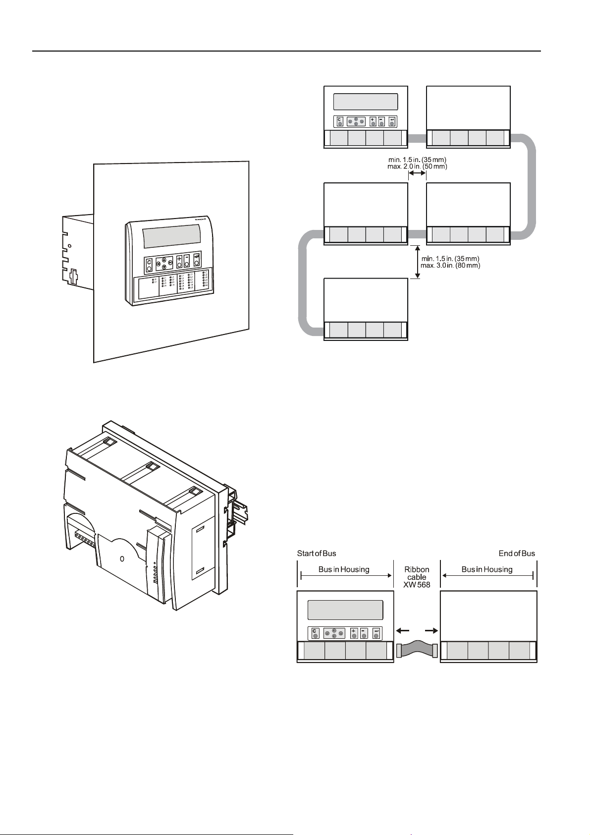
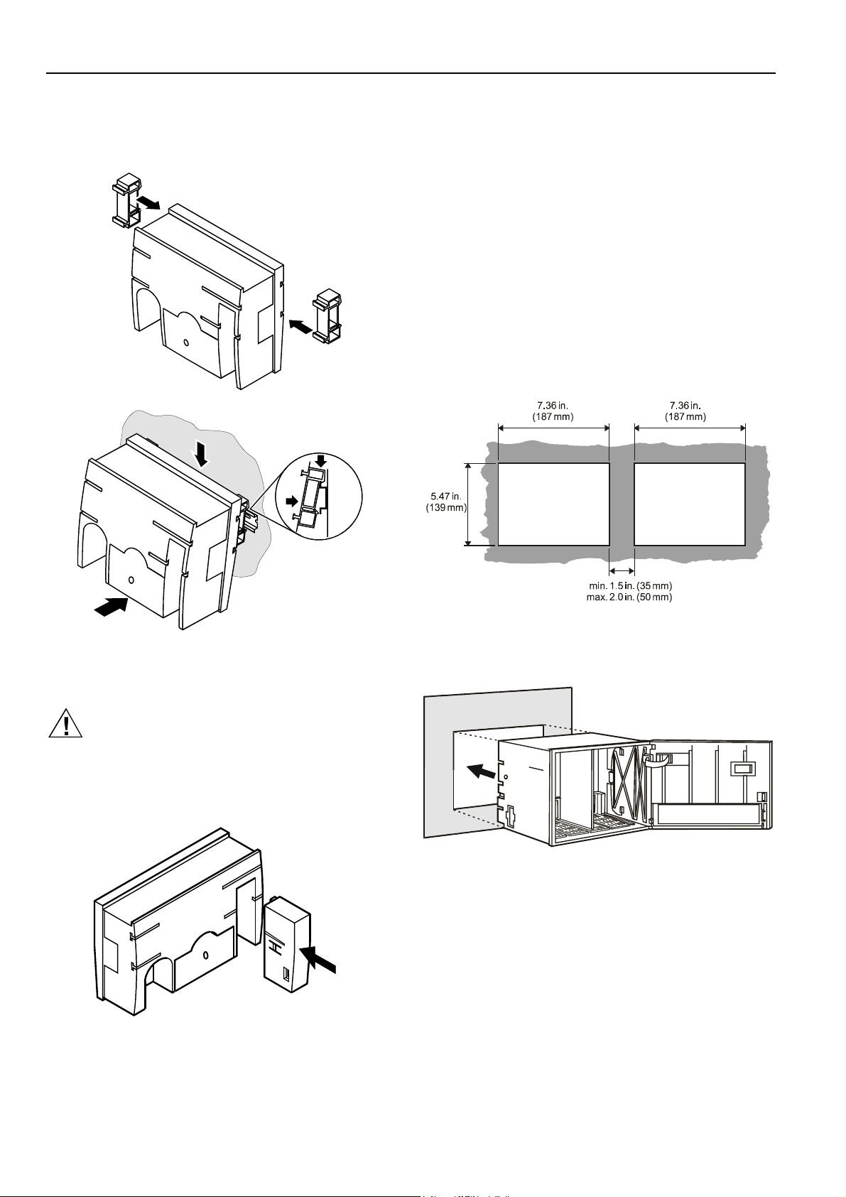
Fig. 1. Excel 500/600 panel door mounting
The Excel 500-XCL5010 can be mounted only on a DIN rail;
control panel door installation is not possible.
Fig. 2. Excel 500-XCL5010 DIN rail mounting
Fig. 3. Up to five housings can be connected together
When housings are alongside one another, a minimum
spacing of 1.5 in. (35 mm) should be taken into consideration
to enable the hinged cover to be opened. The maximum
spacing between housings is limited by tailor-made internal
bus cables as shown in Fig. 3.
Excel 500/600 Internal Bus Wiring (not
XCL5010)
Each housing has four plug-in module locations. The
individual modules are connected by an internal bus in the
housing.
Configurations comprising more than one housing must have
the individual busses in the housings connected to one
another.
Excel 500/600 Housing Layout (not XCL5010)
A controller comprises from one to a maximum of five
housings. The housings may be fitted alongside one another
or, one above the other. Any combination is possible.
EN1R-1047GE51 R0902 6
Fig. 4. Excel 500/600 bus wiring
The connection is made via tailor-made ribbon cables. Two
different types are available:
— Type XW568 3 in. (80 mm) long (for housings alongside
one another)
Page 7
EXCEL 500/600 INSTALLATION INSTRUCTIONS
— Type XW569 13 in. (330 mm) long (for housings one
above the other)
CAUTION
Incorrectly inserted bus cables can destroy the
modules installed.
The internal bus begins at the first housing, containing the
power supply and computer modules, and ends at the last
housing.
The protective bus connection covers must be removed.
Table 1. Internal module locations
Module Type Module location
CPU
Power
supply
AI XF521A / XF526 any
AO XF522A / XF527 any
DI XF523A any
DO XF524A / XF529 not in the 1
3-position
output
XC5010C /
XC6010
XP502 1
XF525A
st
housing, location 4
1
st
housing, location 1
st
housing
st
not in the 1
housing
module
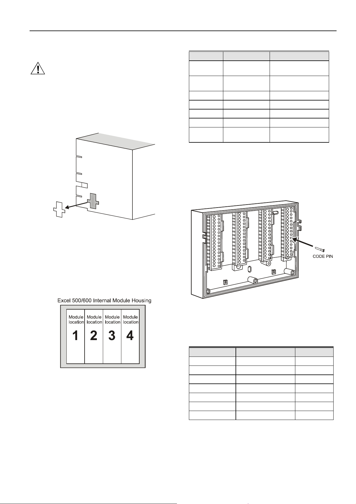
Coding the Terminal Block (not XCL5010)
The terminal block is coded with pins to prevent mixing the
module types during commissioning or servicing. Mixing the
modules can damage them.
You can code the terminal block by inserting pins into
designated location holes on the terminal block in the base.
Fig. 5. Removal of bus connection cover
The overall internal bus length (bus cable and bus in the
housings) must not exceed 6 ft (2m).
Bus cables must be routed at least 2 in. (50 mm) away from
power cables to prevent possible inductive and capacitive
interference.
Module Locations (not XCL5010)
Each housing has four plug-in module locations.
Fig. 6. Internal module numbering
Table 1 shows the plug-in location to which each module may
be assigned:
Fig. 7. Inserting the code pin in the terminal block
Table 2 shows the coding pin positions for the individual
module types:
Table 2. Code pin position by module type
Module Type Pin position
CPU XC5010C, XC6010 08
Power supply XP502 06
AI XF521A, XF526 07
AO XF522A, XF527 11
DI XF523A 09
DO XF524A, XF529 10
3-position output XF525A 12
NOTE: Distributed I/O modules are coded differently. See
Distributed I/O Product Data (EN0B-0090GE51).
7 EN1R-1047GE51 R0902
Page 8
EXCEL 500/600 INSTALLATION INSTRUCTIONS
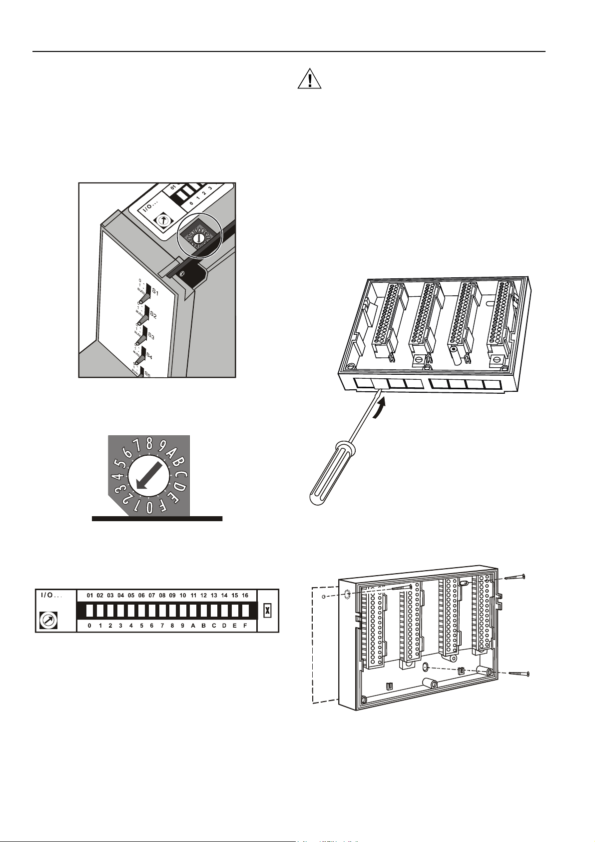
Setting the Module Address (not XCL5010)
In the case of application prior to CARE 4.0, you can set the
module address using the rotary HEX switches located on the
upper surface of the respective input and output modules.
The rotary HEX switch of Distributed I/O modules is situated
within the housing. The XP502 power supply module and the
XC5010C / XC6010 computer modules do not need a
hardware address.
CAUTION
Unplugging a module before switching OFF the power
supply could destroy the module. Do not unplug
modules with the power still connected. First switch
S1 on the power supply module to the 0 position.
Installation Inside a Control Panel
Excel 500/600
IMPORTANT
Observe the minimum spacing of 1.5 in. (35 mm)
when installing more than one housing. Do not exceed the maximum spacing; otherwise, the tailormade internal bus cables will be too short.
1. Break off cable entry strip segments.
Fig. 8. Internal module HEX switch location
The 16 I/O modules (max. including Distributed I/O) are
addressed by means of the rotary HEX switch settings 0 to F.
Fig. 9. Close-up of HEX addressing switch
The relationship between the rotary HEX switch and the
module address can be seen on the label located next to the
rotary HEX switch.
Fig. 10. HEX switch label
Care should be taken to ensure that each module gets its
own module address. Addressing the modules in ascending
order 0 through F is recommended for the sake of clarity for
maintenance personnel.
Fig. 11. Cable entry strip segments
2. Install the base.
EN1R-1047GE51 R0902 8
Fig. 12. Installing the base in the panel
Page 9
3. Code the terminal block (see section "Coding the
Terminal Block (not XCL5010)" on page 7).
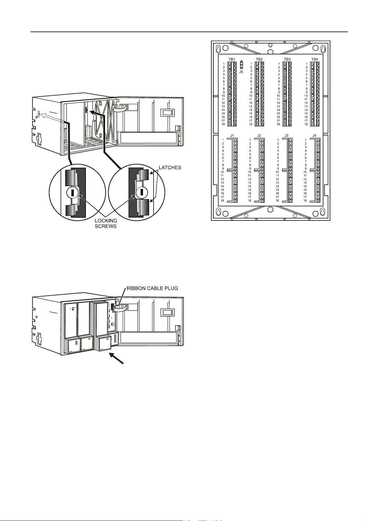
4. Make sure that the locking screws are positioned as
shown in Fig. 13.
5. Plug in the enclosure.
EXCEL 500/600 INSTALLATION INSTRUCTIONS
Fig. 13. Housing locking screws and latches
6. Shift latches inwards until the housing is released.
7. Set the module addresses (see section "Setting the
Module Address (not XCL5010)" on page 8).
8. Insert the modules.
Fig. 14. Modules and ribbon cable
9. Plug the ribbon cable onto the computer module.
10. Close the cover.
Fig. 15. Excel 500/600 extended wiring base
Using the extended wiring base the I/O terminals are
accessible at run-time.
Extended wiring base (wall-mounting, only; US, only):
As an alternative to the base plate, an extended wiring base
may be used. This is available for the U.S. market, only, and
can be ordered without cover plate (OS No. 14507274-001)
or with cover plate (OS No. 14507274-002).
9 EN1R-1047GE51 R0902
Page 10
EXCEL 500/600 INSTALLATION INSTRUCTIONS
0000079
a
0000043
a
Excel 500-XCL5010
1. Attach the DIN rail mounting clips to the housing.
2. Mount the controller on the DIN rail.
1
1
2
Plug in the communication module until it snaps into the controller housing
NOTE: If the communication module has been replaced or
pulled out and plugged in again, push the reset
button after power on.
Installation through a Control Panel Door
(not XCL5010)
IMPORTANT
Observer the minimum spacing of 1.5 in. (35 mm)
when installing more than one housing. Do not exceed the maximum spacing; otherwise, the tailormade internal bus cables will be too short.
1, Prepare the door in accordance with the following.
dimensions.
3
Fig. 16. Mounting Excel 500-XCL5010 on DIN rail
Excel 500-XCL5010 Communication Module
CAUTION
Always plug in the communication module before
connecting the power supply.
Always disconnect the power supply before
unplugging the communication module.
Fig. 18. Panel door mounting dimensions
2. Insert the housing.
Fig. 19. Inserting the housing in the panel door
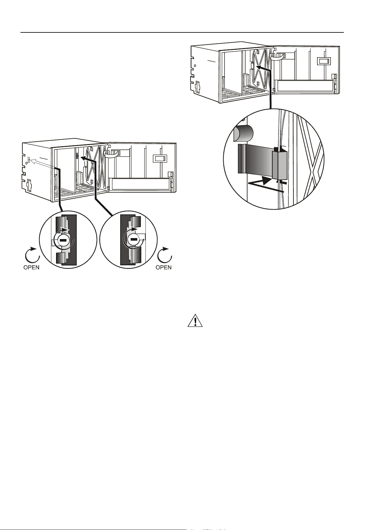
3. Insert the retaining clamp.
Fig. 17. Inserting the communication module
EN1R-1047GE51 R0902 10
Page 11
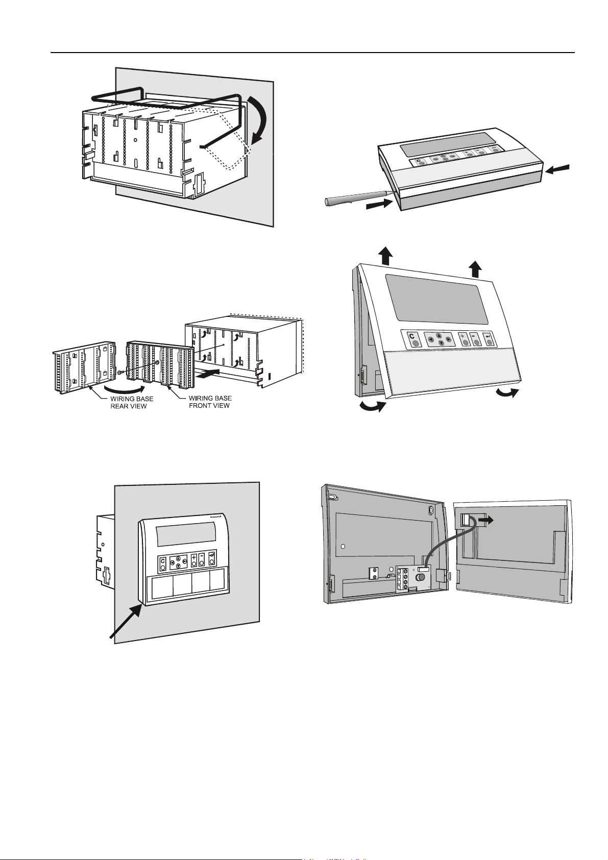
Fig. 20. Housing retaining clamp
4. Turn retaining clamp to fix housing.
5. Code the terminal block (see page 7).
6. Install the base.
EXCEL 500/600 INSTALLATION INSTRUCTIONS
External Installation of XI582AH Operator
Interface
1. Remove the cover.
Fig. 23. Loosening the cover
Fig. 21. Installing the wiring base
7. Complete electrical wiring.
8. Lock the cover.
Fig. 22. Locking the MMI cover
Fig. 24. Removing cover
2. If mounting on a wall, disconnect cable from panel for
easier handling.
Fig. 25. Disconnecting cable from cover
3. Route cable from the computer module (XC6010,
XC5010C, XCL5010).
11 EN1R-1047GE51 R0902
Page 12
EXCEL 500/600 INSTALLATION INSTRUCTIONS
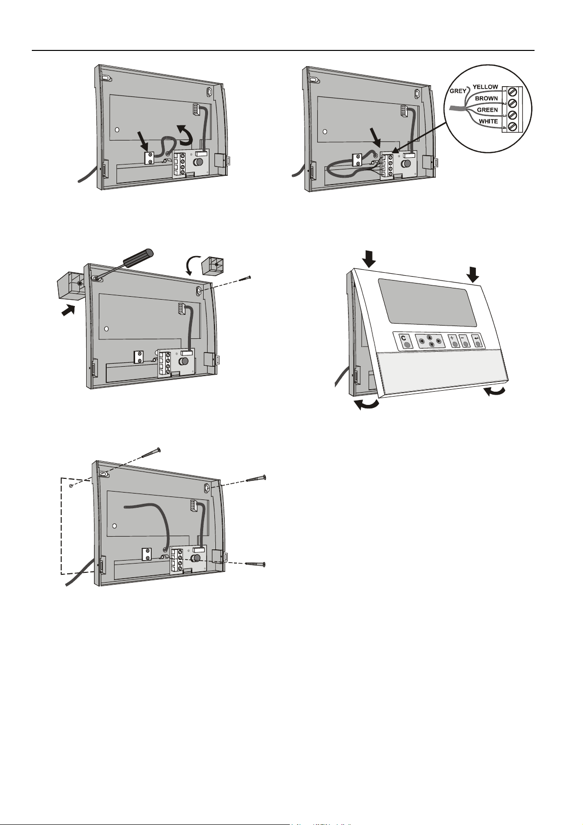
Fig. 26. Routing the cable
4. If mounting on a wall, remove feet.
Fig. 27. Removing feet
5. Attach the housing to the wall.
Fig. 29. Making electrical connections
8. Reattach the cover.
Fig. 30. Reattaching cover
Deactivating Backlit Display of the XI582AH
The XI582AH Operator Interface is equipped with an
integrated backlit display to suit the display to the ambient
lighting conditions. By default, this backlight is ON. This can
be disabled by means of a jumper if required. The jumper is
located at the back of the XI582AH cover.
Fig. 28. Attaching to wall
6. Make electrical connections (gray wire not used).
7. Reconnect cable to panel if removed in step 2.
EN1R-1047GE51 R0902 12
Page 13
EXCEL 500/600 INSTALLATION INSTRUCTIONS
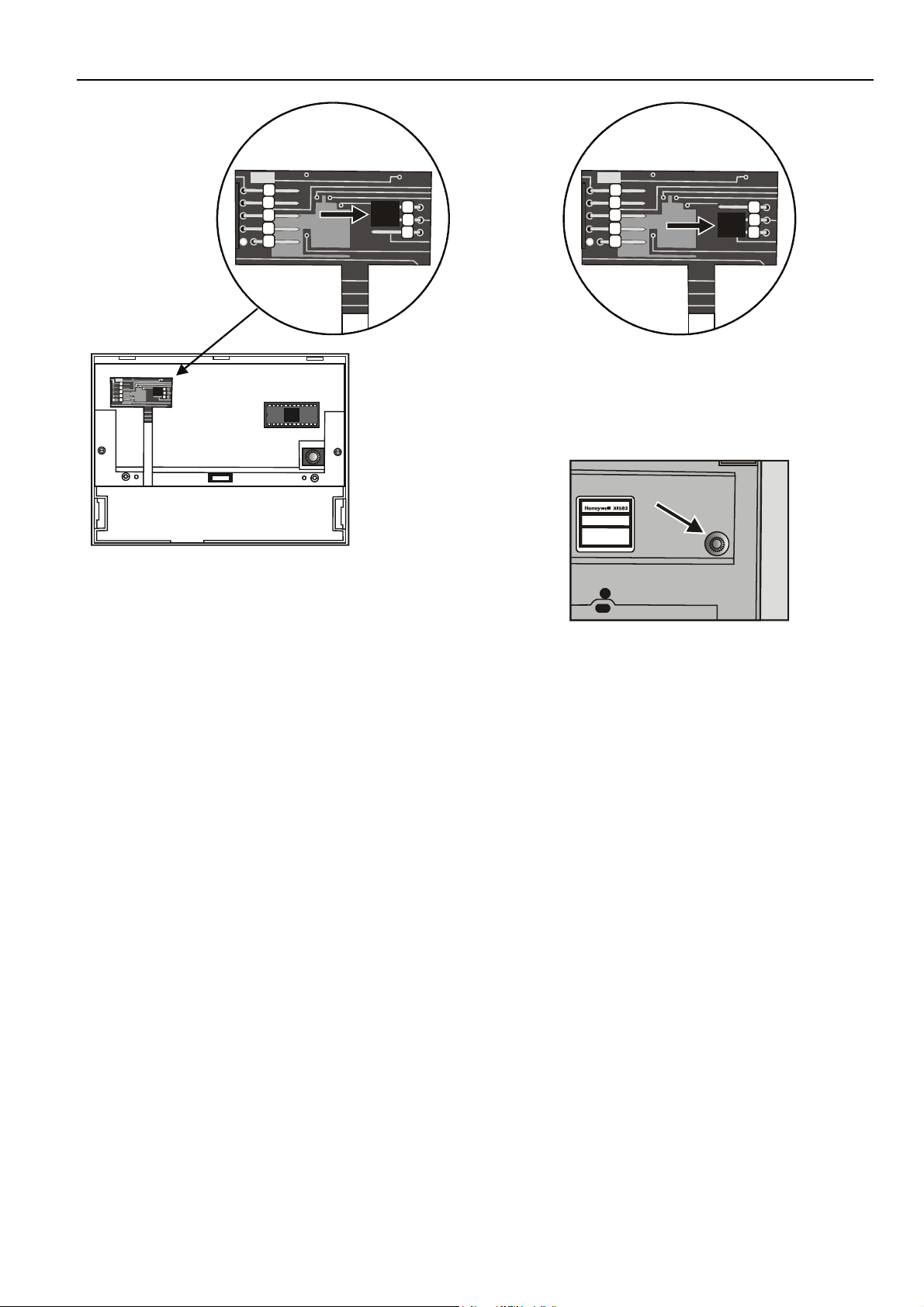
Fig. 32. Backlight OFF jumper position
When the jumper is disabled (OFF-position), the backlight is
permanently deactivated.
The contrast of the display can be adjusted using the
potentiometer at the rear of the unit.
Fig. 31. Jumper location (backlight ON position)
The figure above shows the location of the jumper. To change
jumper position, disconnect the connector first, then pull off
jumper with tweezers or pincers and move to new position.
When the jumper is enabled (ON-position) the backlight will
be activated with the first key press of any of the eight
operating keys. If no entries are made for approximately two
minutes, the backlight turns itself off automatically until the
next key is pressed again.
Fig. 33. Contrast potentiometer
Distributed I/O Installation
Please refer to Distributed I/O Product Data sheet (EN0B0090GE51) for more information.
13 EN1R-1047GE51 R0902
Page 14
EXCEL 500/600 INSTALLATION INSTRUCTIONS
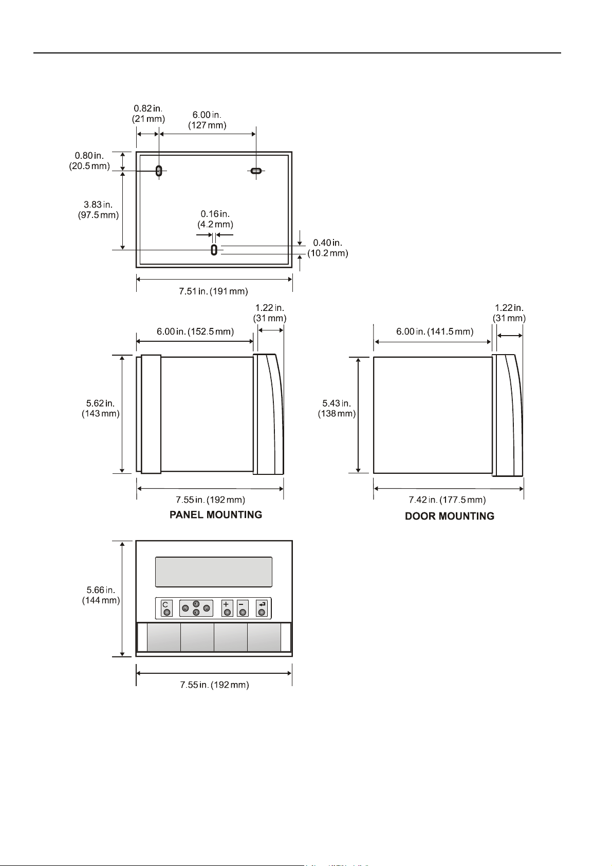
Dimensions
Excel 500/600
Fig. 34. Excel 500/600 outside dimensions
EN1R-1047GE51 R0902 14
Page 15
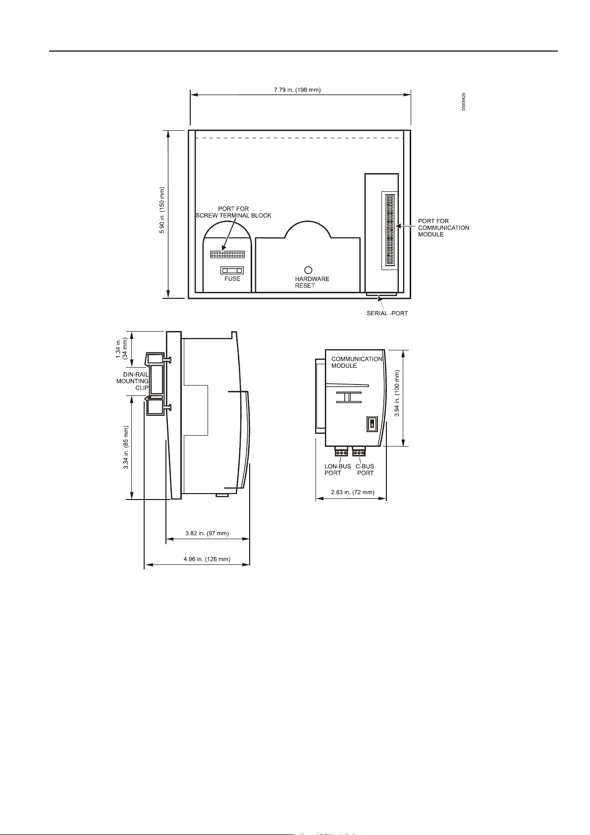
Excel 500-XCL5010
EXCEL 500/600 INSTALLATION INSTRUCTIONS
Fig. 35. Excel 500-XCL5010 dimensions
15 EN1R-1047GE51 R0902
Page 16
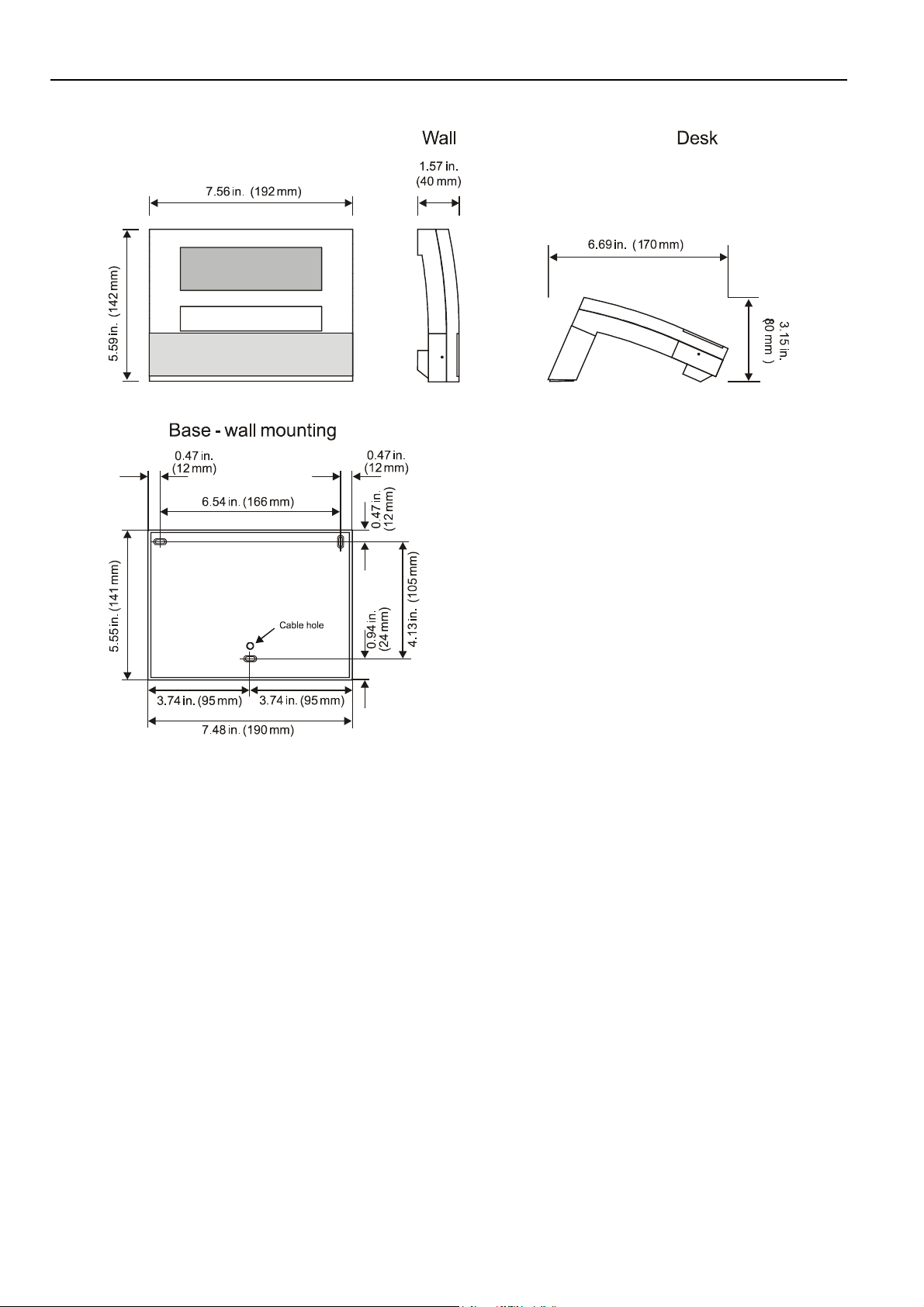
EXCEL 500/600 INSTALLATION INSTRUCTIONS
XI582AH
Fig. 36. XI582AH dimensions
EN1R-1047GE51 R0902 16
Page 17
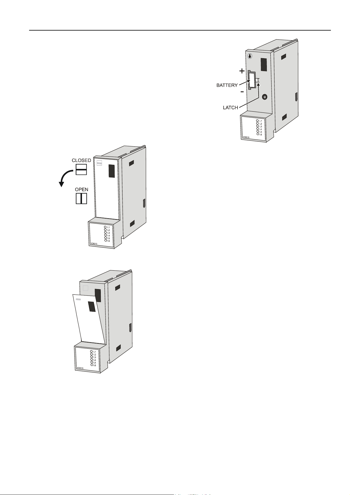
Battery Activation during Commissioning
(XC6010, only)
The controller is delivered from the factory with the battery in
the computer module electrically isolated from the internal
circuitry by a safety tag to prevent the battery from
discharging in transit.
The controller is delivered from the factory with the battery in
the computer module electrically isolated from the internal
circuitry by a safety tag to prevent the battery from
discharging in transit.
1. Unscrew the computer module cover with a
screwdriver.
EXCEL 500/600 INSTALLATION INSTRUCTIONS
Fig. 39. Battery compartment
2. Remove the safety tag.
3. Install the cover.
Replacing the Battery
IMPORTANT
Batteries must not be disposed of as household
waste. The law requires that you as the consumer
return the waste batteries. Dispose of the battery
according to legal regulations
Fig. 37. Accessing the battery compartment
Fig. 38. Removing the faceplate
During normal operation, the battery is periodically tested
under load. If the battery voltage falls below a threshold of
2.45 V during operation or under load, the computer module
generates an error message which is displayed on the MMI
as a system alarm. The battery must be replaced as soon as
possible after the system alarm.
IMPORTANT
The line power supply must not be interrupted while
replacing the battery; otherwise, all data held in RAM
is lost.
NOTE: In the event that your fingers touch the battery
contacts, please clean the contacts with cleaning
agent.
1. Unscrew the computer module cover with a screwdriver
as shown in the previous section.
2. Release the latch holding the battery in its compartment
(See Fig. 39).
3. Remove the old battery.
4. Insert the new battery with the positive contact pointing
upwards.
Battery type:
Lithium battery 3 V, 1000 mAh, e.g. VARTA lithium battery
CR1/2 AA – 3 V, 1000 mAh
17 EN1R-1047GE51 R0902
Page 18
EXCEL 500/600 INSTALLATION INSTRUCTIONS
NOTE: The CPU modules XC5010C and XCL5010 do not
contain a battery. RAM is buffered for 3 days by a
capacitor.
Dismantling the Control Panel Unit
Before dismantling the controller, the low voltage switch S1 of
the power supply module must be switched OFF (position 0).
To dismantle the control panel unit, reverse the steps of the
installation procedure (see page 8). To release the locking
screws in order to remove the wiring base, turn them clockwise as shown in Fig. 40.
Fig. 40. Releasing housing locking screws
Dismantling the Control Panel Door Unit
Before dismantling the system, disconnect the power supply.
To dismantle the control panel unit, reverse the steps of the
installation procedure (see page 10).
Dismantling the Housing Cover
1. Release the metal retaining clamp.
Fig. 41. Housing cover retaining clamp
2. Pull off the cover.
Dismantling the Excel 500-XCL5010 Control
Panel Unit
Before dismantling the system, disconnect the power supply
(e.g. by removing the terminal block or by an additional 3rdparty switch which should be installed onto the DIN rail close
to the controller; see also warnings and notes in section
"Electrical Connections" on page 20).
CAUTION
Always plug in the communication module before
connecting the power supply.
Always disconnect the power supply before
unplugging the Communication module.
EN1R-1047GE51 R0902 18
Page 19

EXCEL 500/600 INSTALLATION INSTRUCTIONS
2
2
1
1
Fig. 42. Removing Excel 500-XCL5010 from DIN rail
1. Dismantle the controller housing as depicted.
2. Pull the lower part of the housing off the control panel.
3. Lift the housing from DIN rail.
0000079b
Dismantling the XI582AH Operator Interface
Use a pencil or similar object to open the XI582AH Operator
Interface.
Fig. 43. Opening the XI582AH Operator Interface unit
19 EN1R-1047GE51 R0902
Page 20

EXCEL 500/600 INSTALLATION INSTRUCTIONS
ELECTRICAL CONNECTIONS
When connecting the controller, both VDE, National Electric
Code NEC (or equivalent) and any local regulations concerning grounding and zero voltage must be observed.
Electrical work should be carried out by a qualified electrician.
Under no circumstances should spare controller terminals be
used as wiring support points. Doing so could damage the
modules.
The electrical connections must be made at the terminal
blocks. The corresponding connection diagrams are on the
individual modules.
WARNING
Switch power OFF before making connections to or
removing connections from terminals to avoid
electrical shock or equipment damage.
IMPORTANT (FOR EUROPE, ONLY)
To comply with CE requirements, devices with a
voltage in the range of 50...1000 Vac or
75...1500 Vdc which are not provided with a supply
cord and a plug or with other means for
disconnection from the supply having a contact
separation of at least 3 mm in all poles, must have
the means for disconnection incorporated in the
fixed wiring.
Cable Routing
The minimum distance to power mains cables is 0.4 in. (10
mm) for shielded cable and 4 in. (10 cm) for unshielded cable.
All low-voltage signal and output cables should be regarded
as communication circuits in accordance with VDE 0100 and
VDE 0800 (or NEC or other equivalent), and should therefore
be routed separately from mains cables.
Joining sensor cables should be avoided.
Shielding Input / Output Module and Power
Supply Cables
Shielding input and output module and power supply cables
is not necessary if the general guidelines for cable routing are
observed. If, in certain cases, the routing guidelines cannot
be observed, then shielded cable must be used.
The shield must not be terminated at a controller; instead, to
avoid ground loops, the shield must be grounded (at only one
end) at the control panel.
To prevent ground loops, shielding of input/output cables
leading to peripheral devices must be grounded only at the
control panel end.
Shielding of Data-Transmitting Cables
Connect the shield of the system bus (C-Bus) to system
ground on both ends. Each end of the shield on the system
bus should be connected to the system ground terminal of the
respective computer module. Do not connect it to the control
panel earth or any other earth ground points.
NOTE: The L
To connect remote operator interface units, ready-made
cables are available (XW565; XW582, XW583, etc.) with the
shield already connected to the computer module plug end.
ONWORKS bus must not be shielded on the
CPU side.
Grounding (XC5010C / XC6010, only)
The controller should be grounded using as short a cable as
possible (minimum 16 AWG [1.5 mm²]) between the control
panel and the terminal block of the power supply module.
System Ground
WARNING
High voltage
Risk of electrical shock or equipment damage.
The controller's system ground must have no
connection with the control cabinet ground!
NOTE: A document providing additional information on
system grounding (if required) is available via the
Honeywell Technical Assistance Center (TAC) or, for
Honeywell employees, on the Docu Server under:
http://web.ge51.honeywell.de/dep/mc/TAC_Tips.
RFI Suppression
Honeywell actuators are RFI (Radio Frequency Interference)
suppressed as standard in accordance with VDE 0871/B and
VDE 0875/N.
EN1R-1047GE51 R0902 20
Page 21
XC5010C / XC6010 Cable Lengths and Sizes
Table 3. Cable sizing
Cross sectional area
Type of signal
24 Vac power
supply
Low voltage
1
signals
1
0 to 10V sensors, totalizers, digital inputs, 0 to 10V signals for
actuators, etc.
PRIMARY
VOLTAGE
24 Vac
TRANSFORMER
≤≤≤≤ 300 ft
(100 m)
≤ 16 AWG
(≥ 1.5 mm
≤≤≤≤ 550 ft
(170 m)
≤ 14 AWG
2
)
(≥ 2.5 mm2)
≤ 20 AWG (≥ 0.5 mm2)
MAX. 1300 ft (400 m)
MIN. 20AWG (0.5 mm2)
24 V
Y
GND
≤≤≤≤ 1300 ft
(400 m)
-
Y
EXCEL 500/600 INSTALLATION INSTRUCTIONS
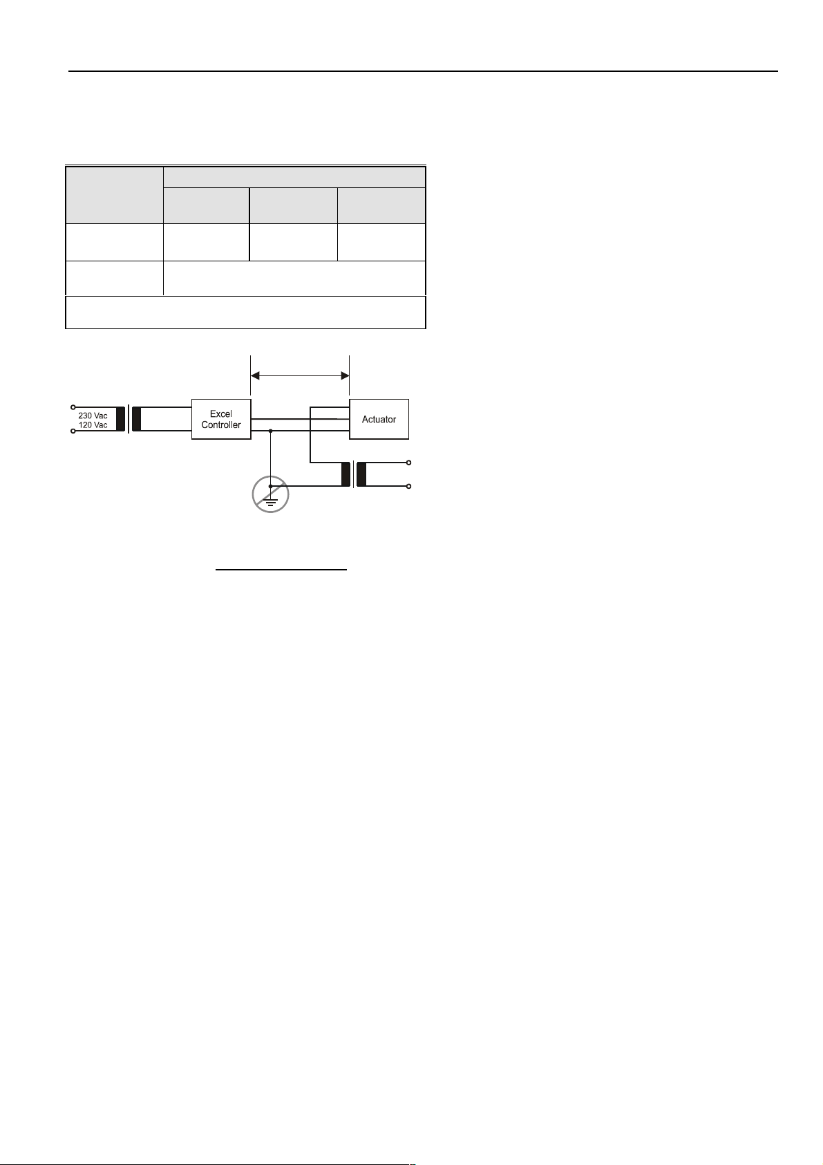
A cable length of 1300 ft (400m) with a cross sectional area of
0.5 mm2 (20 AWG) is permissible for a two-core, 0 to 10 Vdc
signal cable.
Lightning Protection
Please contact your local Honeywell representative for
information on lightning protection.
24 Vac
EXTERNAL
TRANSFORMER
230 Vac
120 Vac
PRIMARY
VOLTAGE
Fig. 44. Connection of XL500/600 controller and a 24 V
actuator with separate transformers
21 EN1R-1047GE51 R0902
Page 22

EXCEL 500/600 INSTALLATION INSTRUCTIONS
Summary of Internal Modules
Table 4. Summary of Excel 500/600 internal modules
Module Name Inputs Outputs Manual override switches LED display
LONWORKS Service LED
C-Bus transmit
Computer module
Computer module XC6010 Reset button
Power supply module XP502 1 0 (1 x)
Analog input module XF521A 8
Analog input module XF526 8 CPU active
Analog output module XF522A 8
Analog output module XF527 8 8 x Output intensity
Digital input module XF523A 12 12 x Status, invertible
Digital output module XF524A
Digital output module XF529
Three-position output
module
C-bus repeater (10 KBit) XD509
NOTE: With XC6010 CPU only, there are submodules for system bus combination, XD505A (10 KBit) / XD508 (1 MBit), and
for stand-alone modem communication, XDM506.
XC5010C,
XC5210C
5 changeover
1 NO contact
5 changeover
1 NO contact
XF525A 3 three-position
Reset button
ONWORKS service button
L
RS232 front-rear switch
0 (5 x)
1
Auto
0 (5 x)
1
Auto
+ (3 x)
0
Auto
C-Bus receive
Normal
System error
RS232 transmit
RS232 receive
Ground loop error
Normal
System error
RS232 transmit
RS232 receive
C-Bus transmit
C-Bus receive
Power supply
Watchdog
ext. battery operation
8 x Output intensity
6 x Status
6 x Status
3 x Open Close
EN1R-1047GE51 R0902 22
Page 23

EXCEL 500/600 INSTALLATION INSTRUCTIONS
Line Power Supply
WARNING
A separate CRT 6 or 1450 series (U.S.) transformer must be
used for each of the EXCEL 500/600 controller's 24 V supply.
No additional loads may be connected !
Each additional XL500/600 controller requires its own
transformer.
An additional transformer, appropriate to the power require-
ments, should be used to power input/output peripherals (e.g.
actuators).
MAX. 1300 ft (400 m)
MIN. 20 AWG (0.5 mm2)
PRIMARY
VOLTAGE
24 V
24 Vac
TRANSFORMER
Fig. 45. Connection of XL500/600 controller and a 24V
actuator with separate transformers
Y
Y
GND
24 Vac
EXTERNAL
TRANSFORMER
230 Vac
120 Vac
PRIMARY
VOLTAGE
Table 5. 1450 series transformers data
Part #
1450 7287
Primary
side
Secondary side
-001 120 Vac 24 Vac, 50 VA
-002 120 Vac
-003 120 Vac
2 x 24 Vac, 40 VA, and 100 VA
from separate transformer
24 Vac, 100 VA, and 24 Vdc;
600 mA
-004 240/220 Vac 24 Vac, 50 VA
-005 240/220 Vac
-006 240/220 Vac
2 x 24 Vac, 40 VA, and 100 VA
from separate transformer
24 Vac, 100 VA, and 24 Vdc;
600 mA
The 1450 series includes built-in fuses, line transient /surge
protection and AC convenience outlet, it meets NEC class 2
requirements.
XC6010 Computer Module
CAUTION
Do not unplug the computer module with the power
still connected, since this could destroy the module.
First, switch S1 on the power supply module to the 0
position.
If one of the C-bus submodules XD505A or XD508 is installed
on the XC6010, follow Fig. 47.
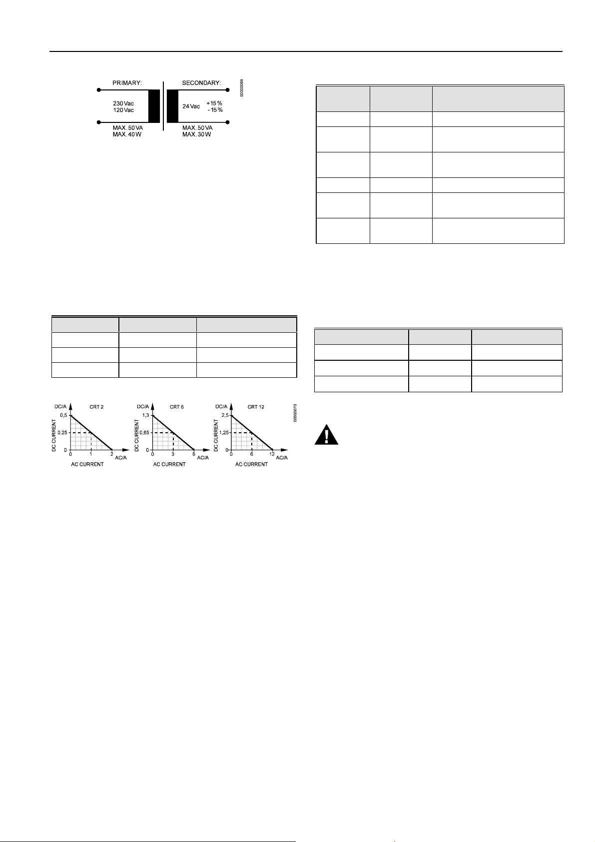
Primary
230 V AC
220 V AC
+ 6 %
-10
%
+10 %
-15 %
Secondary
24 VAC
±20%
CB-0039a
Fig. 46. Excel 500/600 power supply
To avoid interference, the cable between the transformer and
the power supply module should be kept as short as possible
(max. 6 ft (2m)). The transformer should therefore be
positioned close to the power supply module.
Fuse the transformer primary with its own fast-acting 10 A
back-up fuse (or H 16 or L 16 miniature circuit breaker).
The primary coil of the CRT 6 contains a 0.8 A / 250 V quickblow fuse.
Table 5 gives an overview of the transformers of the 1450
series (U.S.):
Fig. 47. Excel 600 CPU module C-Bus connections
The system bus is connected to terminal 16 (C+) and terminal
17 (C-). See also section "C-Bus Termination (Excel 600)" on
page 38.
If the XDM506 Modem Submodule is installed on the
XC6010, follow Fig. 48. Use the XW571 modem cable to
connect the appropriate modem to the wiring terminals.
23 EN1R-1047GE51 R0902
Page 24

EXCEL 500/600 INSTALLATION INSTRUCTIONS
Fig. 50. Excel 600 submodule mounting location
For information pertaining to system bus baud rates and
termination switch settings, see section "C-Bus Termination
(Excel 600)" on page 38.
Fig. 48. Excel 600 CPU modem connection
The XC6010 has 2 EPROMs for the operating system and
one flash EPROM for the application software. Their locations
are shown in Fig. 49.
Fig. 49. Excel 600 EPROM locations
Communication between several Excel 600 controllers is
possible only if the system bus submodule is plugged into
every computer module printed circuit board. This submodule
must be installed when joining several controllers, when
connecting a modem, or when monitoring via a central.
XD505A or XD508 can be used for local bus communication,
XDM506 is used for modem communication. A stand-alone
controller can be operated without a submodule.
XC5010C Computer Module
CAUTION
Do not unplug the computer module with the power
still connected, since this could destroy the module.
First, switch S1 on the power supply module to the 0
position.
The XC5010C computer module contains both the system
bus and the field bus. Fig. 51 shows the pin-out of the
module.
EN1R-1047GE51 R0902 24
Fig. 51. Excel 500 CPU module pin-out
The system bus is connected to terminal 16 (C+) and terminal
17 (C-). The field bus (L
terminals 12 and 13. The L
there is no + or – pin. See section "LONWORKS Bus Wiring"
(page 36) and "System Bus (C-Bus)" (page 37) for more
information.
ONWORKS bus) is connected to
ONWORKS bus is non-polarized, i.e.
Page 25

EXCEL 500/600 INSTALLATION INSTRUCTIONS
NOTE: Shielded cable is not necessary for the LONWORK S
bus.
The serial port connections at the back of the module can be
used to connect an XI582 MMI or, for CPUs with firmware
version V2.1.0 or newer, a modem or ISDN terminal adapter.
See section "Remote Communications" on page 43 for more
information.
Each XC5010C contains an application submodule that is
different from the XD505A/XD508 submodule. The submodule for the XC5010C contains the C-Bus, L
as well as part of the RAM and flash EPROMs. For information on C-Bus baud rates and the bus termination switch,
see section "C-Bus Termination (Excel 500)" on page 38.
ONWORKS bus,
XP502 Power Supply Module
Fig. 53 shows the pin-out of the XP502 Power Supply
module.
Fig. 53. XP502 Power supply module and watchdog
circuit
Fig. 52. Excel 500 CPU module front panel
The operator interface on the front of the computer modules
allow the Xl581AH/XI582AH Operator Interface or the Xl584
Operator and Service Computer to be connected. As an
option, the XI582AH can be connected at the rear of the computer module XC5010C. When connecting to the back of the
module, the switch on the front panel of the XC5010C must
be set to "Rear".
To monitor the line power supply, the watchdog alarm must
be provided with its own power or battery supply.
Controller in operation:
Watchdog relay terminals 17 and 18 connected.
Controller non-operational:
Watchdog relay terminals 16 and 17 connected.
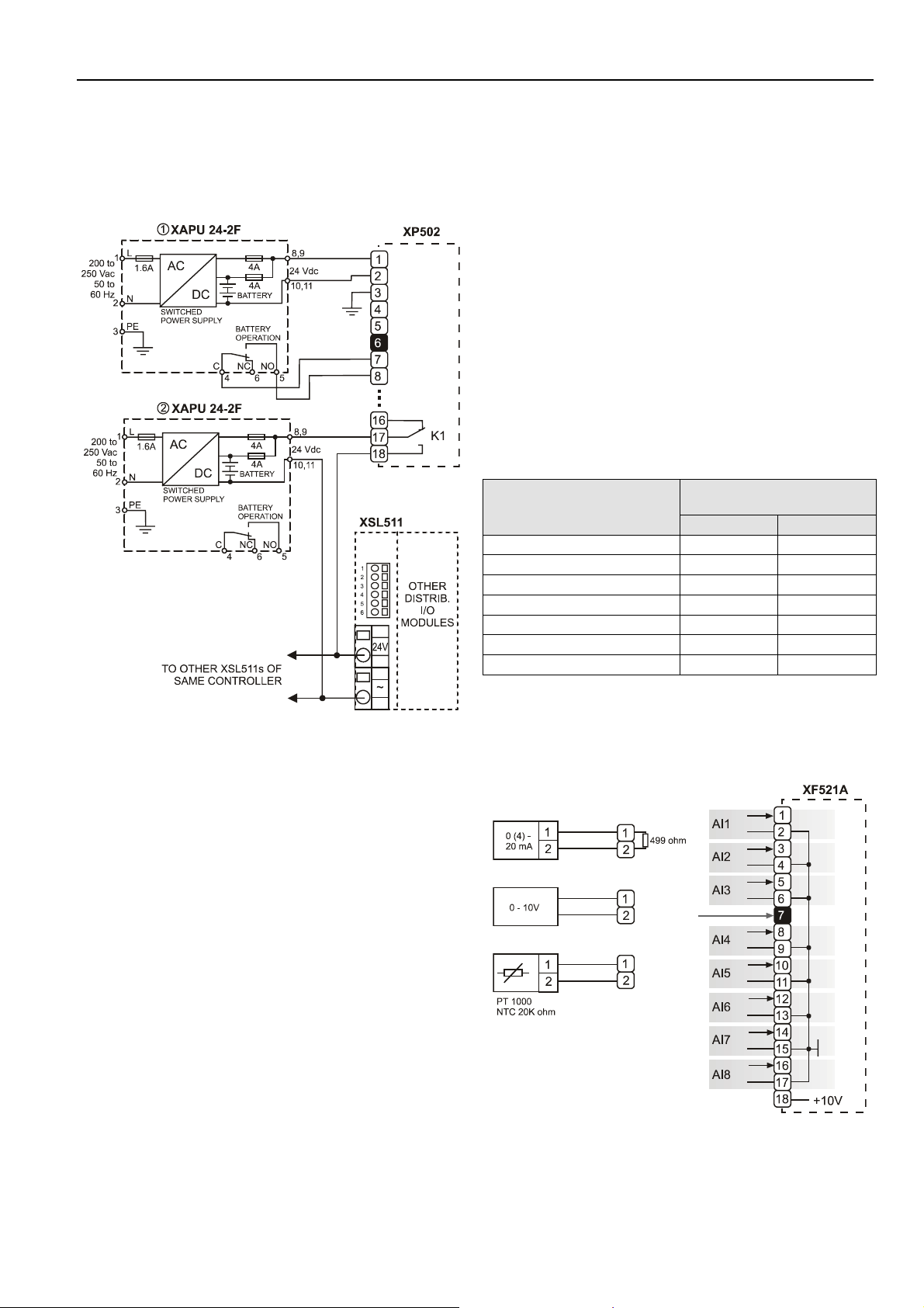
XP502 with External UPS XAPU 24-2F (Internal
Modules, Only)
The Uninterruptable Power Supply XAPU 24-2F contains a
relay contact and 24 Vac, which can be used for external controls, or for the connection from XP502 terminal A7, A8. In
case of failure, the relay contacts C and NO are closed and
the 24 Vac supply is interrupted.
25 EN1R-1047GE51 R0902
Page 26

EXCEL 500/600 INSTALLATION INSTRUCTIONS
Fig. 54. Connection of XAPU 24-2F UPS (internal
modules)
LED (L3) shows operation by battery.
NOTE: The output from the XAPU 24-2F must not be
connected with other devices.
The fully-equipped Excel 500/600 controller will be completely
supported with the battery for at least 15 minutes, without the
mains power 230 Vac.
XP502 with External UPS XAPU 24-2F (Distributed
I/O Modules, Only)
The wiring diagram below is for Excel 500 installations using
only Distributed I/O modules. No internal I/O modules may be
used. No other devices may be connected to the XAPU 242F.
Fig. 55. Connection of XAPU 24-2F UPS (Distributed I/O
modules)
NOTE: There must be no connection between GND of the
XC5010C CPU module and the GND of Distributed
I/O modules.
Relay K1 insures that the supply of the Distributed I/O
modules will be switched OFF by switching OFF the XP502
Power Supply module.
The power consumption of the Excel 500 controller is shown
in the table below. For the power consumption of Distributed
I/O modules, please refer to the corresponding Product Data
(EN0B-0090GE51)
Table 6. Power consumption of Excel 500 controller
Devices powered
XP502, XC5010C,
XI581 (backlight ON)
XP502, XC5010C 140 mA 130 mA
Supply voltage
24 Vdc 28.8 Vdc
170 mA 155 mA
EN1R-1047GE51 R0902 26
Page 27
EXCEL 500/600 INSTALLATION INSTRUCTIONS
XP502 with External UPS XAPU 24-2F (Distributed
I/O and Internal Modules)
As shown in the figure below, two XAPU 24-2F UPSs are
required when the controller has both internal and Distributed
I/O modules connected.
XF521A Analog Input Module
Technical Specifications
Number:
eight inputs (AI1 – AI8)
Input:
0...10 Vdc (low-input impedance, 25kOhm to 10 V /
200kOhm to GND);
0...20 mA (via external 500-ohm resistor);
4...20 mA (via external 500-ohm resistor);
NTC 20K ohm (-50...+150 °C);
PT1000 (-50...+150 °C)
Protection:
up to 40 Vdc / 24 Vac
Resolution:
12-bit resolution
Accuracy:
±75 mV or 0.75% (0...10 V)
Table 7. Accuracy of analog input sensors
Measurement error (without
Range
-58...-4 °F (-50...-20 °C) ≤ 1.2 K ≤ 5.0 K
-4...+32 °F (-20...0 °C) ≤ 0.7 K ≤ 1.0 K
+32...86 °F (0...30 °C) ≤ 0.5 K ≤ 0.3 K
86...158 °F (30...70 °C) ≤ 0.7 K ≤ 0.5 K
158...212 °F (70...100 °C) ≤ 1.2 K ≤ 1.0 K
212...266 °F (100...130 °C) ≤ 1.2 K ≤ 3.0 K
266...302 °F (130...150 °C) ≤ 1.2 K ≤ 5.5 K
sensor tolerance)
PT1000 NTC 20K
Fig. 56. Connection of XAPU 24-2F UPS (internal and
Distributed I/O modules)
XAPU 24-2F number 1 is connected to the XP502 for the
controller, only. No other devices may be powered by XAPU
number 1.
XAPU 24-2F number 2 is connected to the XSL511
LONWORKS connector modules for powering the Distributed
I/O modules. The connection through relay K1 of the XP502
insures that the power supply to the Distributed I/O modules
will be switched OFF when the XP502 is switched OFF.
With current sensors, a terminating resistor of R1 = 499 ohms
± 0.25 % must be connected.
Terminal 18 is an auxiliary output voltage (+10 Vdc, I
5 mA) available for various sensor circuits.
Fig. 57. XF521A Analog Input module connections
max
=
27 EN1R-1047GE51 R0902
Page 28

EXCEL 500/600 INSTALLATION INSTRUCTIONS
Fig. 58 shows several connection examples for various
sensors: WS21 Wind Sensor; SAF 25 Solar Sensor; and VMP
Feedback Potentiometer.
Fig. 58. XF521A connection examples
Fig. 59 shows connections to a TF26.
Terminals 1, 3: temperature adjustment
Terminals 5, 3: room sensor
Terminals 6, 3: LED
XF526 Analog Input Module
Technical Specifications
Number:
eight inputs (AI1 – AI8)
Input:
0...10 Vdc (low-input impedance, 25kOhm to 10 V /
200kOhm to GND);
0...20 mA (via external 500-ohm resistor);
4...20 mA (via external 500-ohm resistor);
NTC 20K ohm (-50...+150 °C);
PT1000 (-50...+150 °C)
PT1000 (0...+400 °C)
PT100 (-50...+150 °C)
PT3000 (-50...+150 °C)
Balco 500 (-50...+150 °C)
Protection:
up to 40 Vdc / 24 Vac
Resolution:
12-bit resolution
Accuracy:
±75 mV or 0.75% (0...10 V)
Table 8. Accuracy of analog input sensors
Measurement error (without
Range
-58...-4 °F (-50...-20 °C) ≤ 1.2 K ≤ 5.0 K
-4...+32 °F (-20...0 °C) ≤ 0.7 K ≤ 1.0 K
+32...86 °F (0...30 °C) ≤ 0.5 K ≤ 0.3 K
86...158 °F (30...70 °C) ≤ 0.7 K ≤ 0.5 K
158...212 °F (70...100 °C) ≤ 1.2 K ≤ 1.0 K
212...266 °F (100...130 °C) ≤ 1.2 K ≤ 3.0 K
266...302 °F (130...150 °C) ≤ 1.2 K ≤ 5.5 K
sensor tolerance)
PT1000 NTC 20K
Fig. 59. XF521A and TF26 example
EN1R-1047GE51 R0902 28
With current sensors, a terminating resistor of R1 = 499 ohms
± 0.25 % must be connected.
Terminal 18 is an auxiliary output voltage (+10 Vdc,
= 5 mA) available for various sensor circuits.
I
max
Page 29

EXCEL 500/600 INSTALLATION INSTRUCTIONS
Fig. 61. Digital input hysteresis
The LED functionality of each digital input channel can be
altered via 12 internal DIP switches. In the ON position
(default), the LED will illuminate when energized (normally
open contacts). In the OFF position, the LED will illuminate
when de-energized (normally closed contacts).
Fig. 60. XF526 Analog Input module connections
XF523A Digital Input Module
The digital input module can process DC or AC voltage
signals. The module has 12 digital inputs. When the input
voltage reaches 5 V, the digital signal is set to a status of "1".
With a hysteresis of 2.5 V, the digital input signal must fall
below 2.5 V before a digital status of "0" is reported.
Max. signal voltage from non-Honeywell voltage sources:
DC Voltage: V
AC Voltage: V
= 40 V
max
= 28 V / ≥ 50 Hz
max
Input resistance:
= 15k ohms
R
i
Fig. 62. XF523A connection examples
If the inputs are used as totalizers, Table 9 applies.
Table 9. Totalizer inputs specifications
Input Frequency Pulse duration Pulse internal Chatter time
1, 2 max. 15 Hz min. 20 ms min. 33 ms max. 5 ms
3 to 12 max. 0.4 Hz min. 1.25s min. 1.25 s max. 50 ms
The inputs shown in row one (Input 1 to 2) may be used as fast totalizers. In this case, the input signal characteristics of row one
are valid. If they are not used as fast totalizers, the values of row two (Inputs 3 to 12) apply to them as well.
29 EN1R-1047GE51 R0902
Page 30

EXCEL 500/600 INSTALLATION INSTRUCTIONS
XF522A and XF527 Analog Output Modules
Technical Specifications
Number:
8 analog outputs
Voltage rating:
0 to 10 V, max. 11V
Current rating:
1 mA max.
Resolution:
8 bit
Accuracy:
±150 mV or 1.5% deviation from output voltage
Manual override switches:
XF522A 5 manual override switches (AO1 to AO5)
XF527 No manual override switches
XF524A and XF529 Digital Output Modules
Technical Specifications
Number:
6 digital outputs
Voltage rating:
240 Vac max. per contact and per module
Current rating:
4 A max. per contact, 12A max. per module
Relay contacts:
K1 to K5:
changeover contact (voltage-free)
K6:
normally open contact (voltage-free)
Fig. 63. XF522A and XF527 Analog Output modules
NOTE: The maximum output current of 1 mA must not be
exceeded.
NOTE: Both modules are fully pin compatible.
Fig. 64. XF524A and XF529 Digital Output module
NOTE: Maximum voltage for U.S. is 24 V.
NOTE: Both modules are fully pin compatible.
Beginning with V3.04.00 firmware, the online point attribute
normally open/normally closed (NO/NC) defines the relation
between the physical input signal and its logical status. See
Table 10.
Table 10. NO/NC attribute and output characteristic
Relay On/Off NO/NC attribute Logical status
On NO 1
Off NO 0
On NC 0
Off NC 1
EN1R-1047GE51 R0902 30
Page 31

EXCEL 500/600 INSTALLATION INSTRUCTIONS
XF525A Three-Position Output Module
Technical Specifications
Voltage rating:
240 Vac or 28 Vdc max.
Current rating:
0.2A max. at 240 Vac
1.2A max. at 28 Vdc
An L 16 miniature circuit breaker or G 10 A quick blow fuse
should be used to protect the 240 Vac mains supply.
NOTE: The maximum voltage for the U.S. is 24 V.
Fig. 65. XF525A Three-position output module
31 EN1R-1047GE51 R0902
Page 32
EXCEL 500/600 INSTALLATION INSTRUCTIONS
,
t
Excel 500-XCL5010
The Excel 500-XCL5010 housing comprises a removable
screw terminal block for direct power supply wiring. For
proper installation of the terminal block, follow these
instructions:
1. Read the complete chapter "Installation" carefully.
2. Follow the instructions from the chapter Screw Terminal
Block Installation Procedure on page 33.
The screw terminal block is attached directly to the controller
housing.
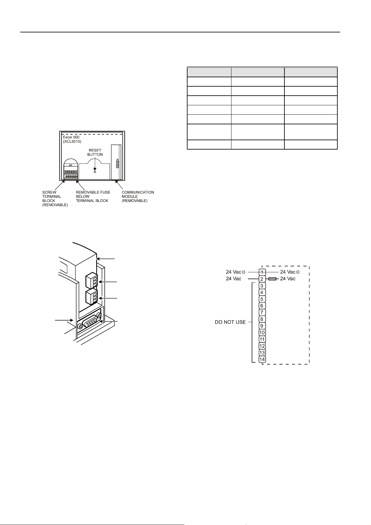
Fig. 66. Excel 500-XCL5010 terminal block location
Table 11. Signals of serial port
Signal type Controller output Controller input
Signal ground
Transmit x
Receive x
Carrier detect x
Clear to send x
Data terminal
ready
x
5 V x
MMI Connection
For direct communication the external operator interface
XI582 and the PC-based MMI XI584 can be connected to the
serial port.
Power Supply
The Excel 500-XCL5010 controller is powered by an external
transformer.
Serial Port
COMMUNICATION
MODULE
C-BUS
CONNECTOR
LON-BUS
CONNECTOR
EXCEL 500XCL5010
HOUSING
SERIAL PORT
FOR EXTERNAL MMI
MODEM, OR ISDN
TERMINAL ADAPTER
Fig. 67. Serial port
The serial port has a 9-pin sub-D connector and has a default
communication speed of 9.6 Kbaud.
Comm_Pr
IMPORTANT
Only the terminals 1 and 2 of the terminal block may
be used for power supply. Do not wire any of the
terminals 3 to 14.
Fig. 68. Excel 500-XCL5010 power terminals location
Terminal 2 is protected by a 4 A quick-acting fuse.
Transformer requirements for one Excel 500-XCL5010
Controller:
Voltage 21 to 26.5 Vdc or 24 Vac ± 20%
Current 1.6A max.
The transformer, already installed in the cabinet, can be used
to supply several controllers, communication devices, or
peripherals like actuators, etc. if the transformer provides
sufficient power.
EN1R-1047GE51 RR0902 32
Page 33
EXCEL 500/600 INSTALLATION INSTRUCTIONS
Table 13. 1450 Series transformers
Fig. 69. Transformer example
Use quick-acting backup fuse 10 A (or automatic H16 or L16)
to protect transformer primary side. On the primary side of the
CRT 2, there is a fusible output of type M 0.315 A (T) 250 V
for the purpose of fine fusing.
NOTE: When selecting the appropriate transformer, con-
sider the number of Distributed I/O modules (see
worst-case power consumption information below) to
be used as well as the power requirements of all
active sensors and actuators connected to the
transformer.
CRT-Series
Table 12. Overview of CRT Series AC/DC current
Transformer max. AC current max. DC current
CRT 2 2 A 0.5 A = 500 mA
CRT 6 6 A 1.3 A = 1300 mA
CRT 12 12 A 2.5 A = 2500 mA
Part #
1450 7287
-001 120 Vac 24 Vac, 50 VA
-002 120 Vac
-003 120 Vac
-004 240/220 Vac 24 Vac, 50 VA
-005 240/220 Vac
-006 240/220 Vac
Standard Transformers
Standard commercially available transformers must fulfill the
specifications stated in Table 14.
Table 14. Requirements for standard transformers
Output voltage Impedance AC current
24.5 Vac to 25.5 Vac
24.5 Vac to 25.5 Vac
24.5 Vac to 25.5 Vac
Primary side Secondary side
2 x 24 Vac, 40 VA and 100 VA
from separate transformer
24 Vac, 100 VA and 24 Vdc
600 mA
2 x 24 Vac, 40 VA and 100 VA
from separate transformer
24 Vac, 100 VA and 24 Vdc
600 mA
≤ 1.15 ohms
≤ 0.40 ohms
≤ 0.17 ohms
max. 2 A
max. 6 A
max. 12 A
Fig. 70. AC/DC current graphs
1450 Series
All transformers of the 1450 series are designed for 50/60 Hz
AC and have insulated accessory outputs. The transformers
include built-in fuses, line transient/surge protection and AC
convenience outlets and meet NEC class 2 requirements.
Screw Terminal Block Installation Procedure
WARNING
High Voltage
Risk of death or electrical shock.
— Do not connect line power supply directly to the
terminals.
— Insulate devices with 120 Vac / 230 Vac by a
transformer.
1. Make sure that the power supply of the cabinet is
disconnected.
2. Make sure that the power supply of the cabinet is
disconnected and the communication module is
plugged in the housing.
IMPORTANT
When installing a separate external transformer, do
not connect the cabinet ground to the controller
system ground.
3. If the distance between the controller and an actuator or
sensor with 24 Vac supply is greater than 550 ft
(170m):
a) Choose a transformer from the transformers
listed in section "Power Supply" on page 32.
b) Connect the chosen transformer directly to the
actuator or sensor.
33 EN1R-1047GE51 R0902
Page 34

EXCEL 500/600 INSTALLATION INSTRUCTIONS
4. Select one of the transformers of the CRT-series or
1450 series from the tables on the previous page or
take a commercially available standard transformer
fulfilling the requirements listed in Table 14.
5. Make sure that the communication module is attached
to the controller housing.
IMPORTANT
The transformer feeding the Excel 500 Controller
must be in the same cabinet. For the selection of the
transformer, the max. DC current must be
considered if field devices with DC load are used.
The secondary side of the transformer must not be
connected to earth ground.
Fig. 71. Connecting the power supply
6. Connect the 24 Vac (-) on the secondary side of the
transformer to terminal 1 on the Screw Terminal Block.
7. Connect the 24 Vac on the secondary side of the
transformer to terminal 2 on Screw Terminal Block.
Fig. 72. Connecting to a screw terminal
Fig. 73. Attaching screw terminal block
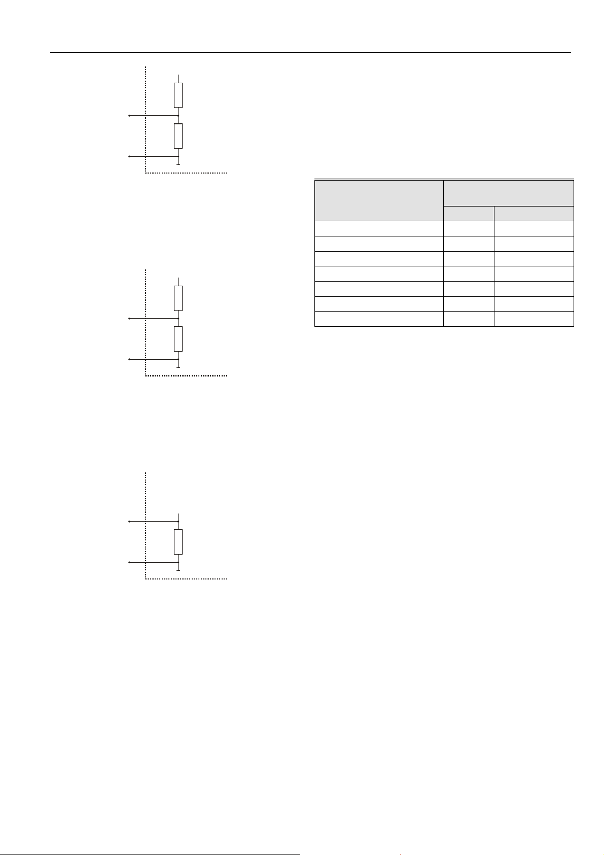
Pull-Up Resistor Handling (O.S. 2.04.00 or higher,
except for XFL521A)
High-Impedance Sensors and Active Sensors
When high-impedance sensors and active sensors are
connected to the inputs, the recognized value will not differ
significantly from the measured value if the pull-up resistor is
de-activated as follows:
Put the character “@” as the first digit of the chosen input
characteristic name in the CARE text editor.
Example:
Characteristic name: @0-10V; the internal pull-up resistor is
disabled.
10 Vdc
Vi
Fig. 74. Analog input / high-impedance sensors
200K ohm
ground
IMPORTANT
If there already are additional transformers, for
example supplying actuators or active sensors,
connect the 24 Vac (-) (secondary side) of the
transformers together.
8. Attach the terminal blocks to the housing as shown in
Fig. 73.
EN1R-1047GE51 RR0902 34
NTC and Low-Impedance Sensors
Characteristic name: NTC; the internal pull-up resistor is
enabled.
Page 35
EXCEL 500/600 INSTALLATION INSTRUCTIONS
10 Vdc
25K ohm
Vi
200K ohm
ground
Fig. 75. Analog input / low-impedance sensors
Pull-Up Resistor Handling when Using Analog Inputs as
Digital Inputs (O.S. 2.03.xx)
When the input is identified as a DI point in CARE (DI
subtype AI), the internal pull-up resistor is enabled.
10 Vdc
25K ohm
Vi
200K ohm
Immersion temperature sensor VF 100
Air duct temperature sensor LF 100
Wind sensor:
Wind sensor WS21.
Further connections:
Temperature sensor terminal TF26
Table 15. Accuracy of analog input sensors
Measurement error
Range
(without sensor tolerance)
Pt1000 NTC (20k ohms)
-58 to –4 °F (-50 to –20 °C) ≤ 1.2 K ≤ 5.0 K
-4 to 32 °F (-20 to 0 °C)
32 to 86 °F (0 to 30 °C)
≤ 0.7 K ≤ 1.0 K
≤ 0.5 K ≤ 0.3 K
86 to 158 °F (30 to 70 °C) ≤ 0.7 K ≤ 0.5 K
158 to 212 °F (70 to 100 °C)
212 to 266 °F (100 to 130 °C)
266 to 302 °F (130 to 150 °C)
≤ 1.2 K ≤ 1.0 K
≤ 1.2 K ≤ 3.0 K
≤ 1.2 K ≤ 5.5 K
ground
Fig. 76. Analog inputs identified as DI point (O.S. 2.03.xx)
Pull-Up Resistor Handling when Using Analog Inputs as
Digital Inputs (O.S. 2.04.00 or higher)
When the input is identified as a DI point in CARE (DI subtype
AI), the internal pull-up resistor is disabled.
10 Vdc
Vi
200K ohm
ground
Fig. 77. Analog inputs identified as DI point (O.S. 2.04.00
or higher)
Sensors and Transducers
Passive sensors (NTC 20k ohms)
Room temperature sensor RF20
Inlet temperature sensor VF20A
External temperature sensor AF20
Active sensors (0 to 10 V):
Duct Humidity Sensor H7011A1000
Duct Humidity Sensor H7012A1009
Active sensors (0 (4) to 20 mA):
35 EN1R-1047GE51 R0902
Page 36

EXCEL 500/600 INSTALLATION INSTRUCTIONS
COMMUNICATIONS
LONWORKS Bus Wiring
Connection between the Distributed I/O modules and the
CPU are made from the LONWORKS connector module
XSL511. The L
uses transformer isolation so that the bus wiring does not
have a polarity; that is, it is not important which of the two
ONWORKS bus terminals are connected to each wire of the
L
twisted pair.
The L
ONWORKS bus can be wired in daisy chain, star, loop or
any combination thereof as long as the maximum wire length
requirements given below are met. The recommended
configuration is a daisy chain with two bus terminations. This
layout allows for maximum L
simple structure presents the least number of possible
problems, particularly when adding on to an existing bus.
Table 16. Doubly-terminated bus specifications
Belden 85102 2700 m (8900 ft)
Belden 8471 2700 m (8900 ft)
Level IV, 22 AWG 1400 m (4600 ft)
JY (St) Y 2x2x0.8 900 m (3000 ft)
TIA568A Categ. 5 24AWG, twisted pair 900 m (3000 ft)
NOTES: The cable types listed above are as recommended
IMPORTANT
The FTT specification includes two components that must be
met for proper system operation. The distance from each
transceiver to all other transceivers and to the termination
must not exceed the maximum node-to-node distance. If
multiple paths exists, the maximum total wire length is the
total amount of wire used.
Table 17. Free topology (singly-terminated) specifications
Cable type
Belden 85102 1650 ft (500m) 1650 ft (500m)
Belden 8471 1300 ft (400m) 1650 ft (500m)
Level IV, 22AWG 1300 ft (400m) 1650 ft (500m)
JY (St) Y 2x2x0.8 1050 ft (320m) 1650 ft (500m)
TIA568A Category 5
24AWG, twisted pair
ONWORKS bus is a 78-kilobit serial link that
ONWORKS bus length, and its
Cable type Max. bus length
by Echelon in their FTT-10A User Guide. The cable
recommended by Honeywell is the level IV, 22
AWG, solid core, nonshielded cable. Belden part
numbers are 9H2201504 (plenum) and 9D220150
(non-plenum).
It is recommended that ferrules not be used to
terminate stranded wires to be inserted in the
Distributed I/O Terminal blocks spring-clamp
terminals.
Max. node-to-
node distance
Max. total wire
length
825 ft (250m) 1500 ft (450m)
IMPORTANT
Do not use different wire types or gauges on the
ONWORKS network segment. The step
same L
change in line impedance characteristics would
cause unpredictable reflections on the bus.
NOTE: In the event that the limit on the total wire length is
exceeded, then FTT physical layer repeaters
(FTT 10A) can be added to interconnect segments
and increase the overall length by an amount equal
to the original specification for that cable type and
bus type for each repeater used. For example,
adding repeaters for a doubly-terminated bus using
JY (St) Y 2x2x0.8 cable increases the maximum
length 3000 ft (900 m) for each repeater.
On the Excel 500-XCL5010 controller, the L
ONWORKS bus
connections are located on the communication module as
shown in Fig. 78:
LON SERVICE BUTTON
POWER, GRN
LON
BUS
12
LON SERVICE, RED
C-BUS TxD, YEL
C-BUS RxD, YEL
RESERVED
C-BUS
TERMINATION
SWITCH
45
3
A1
A2
6
C-BUS
C -
C +
SHIELD
NOT USED
LEDs
00000124
Fig. 78. Excel 500-XCL5010 communication module
LONWORKS Bus Termination
Depending upon the configuration, either one or two
termination modules are required for terminating a L
bus with FTT devices on it. The following two different
L
ONWORKS termination units are available for this purpose:
• 209541B LONWORKS Bus Termination Module (see Fig.
79 and Fig. 80) and
• XAL-Term L
ONWORKS connection and termination
module (see Fig. 81), which can be mounted on DIN rails
and in fuse boxes.
Fig. 79. Termination Module 209541B connections for
doubly-terminated FTT network
ONWORKS
EN1R-1047GE51 RR0902 36
Page 37

EXCEL 500/600 INSTALLATION INSTRUCTIONS
Submodule Selection (XC6010)
Two submodules for system bus communication are
available. The selection depends on the communication
speed.
Fig. 80. Termination Module 209541B connections for a
singly-terminated FTT network
l
l
e
w
removable screw-type
3-pole terminal block
y
e
n
Ho
m
r
e
T
-
L
A
X
4
3
L
L
O
O
N
N
shield
plug-in
jumper
3 4
1
0 6
LON
Termination
FTT/LPT Bus
FTT/LPT Free
Park Position
5
shield
Fig. 81. XAL-Term
In the case of either a daisy chain or free-topology LONWORKS
bus layout, the maximum lengths described above must be
adhered to.
System Bus (C-Bus)
Up to 30 controllers can communicate with one another and a
PC central via the system bus. Instead of an Excel 500/600
controller, other system bus compatible components can also
be connected. (Excel IRC Multicontroller; Excel EMC).
The system bus must be connected through the individual
controllers (open ring).
Table 18. C-Bus submodule baud rates
Submodule Possible baud rates
XD505A 9600 baud
XD508 9600 baud
19200 baud
76800 baud
If the system bus speed throughout the system life-time is
restricted to 9600 baud, then a submodule XD505A should be
chosen. Otherwise, the XD508 must be used.
NOTE: All communication submodules on one bus must be
of the same type, i.e. either uniquely XD505A or
uniquely XD508. Do not use a mix between
submodules XD505A and XD508 on the same bus.
IMPORTANT
For communication with more than 9600 baud it is
required to enable the termination of the first and the
last device on the C-bus (see the following sections).
The controllers with termination must be switched
ON prior to the controllers in the middle of the C-bus.
The C-bus might not work if the controllers with
termination are switched OFF.
The maximum communication speed of the XC5010C /
XCL5010 is 76800 baud. The XC5010C/XCL5010 can be
mounted together with the XC6010 (with XD505A or XD508
submodule) since the XC5010C/XCL5010 communication
speed can be changed to match either submodule.
Fig. 82. C-bus topology
IMPORTANT
Star connection is not permissible because
uncontrollable line reflections may occur.
For setting up the system bus in the right way, three steps
have to be followed:
1. Select submodule for system bus communication
(XC6010, only)
2. Specify cable for system bus.
3. Set up submodule (XC6010), CPU module (XC5010C),
or communication module (XCL5010).
NOTE: When changing the baud rate of bus devices, proper
communication cannot be ensured until all bus
devices are set to the same baud rate again.
NOTE: When adding or removing a controller to/from the C-
Bus, it may take up to two minutes to re-initialize the
bus. During this time, communication on the C-bus is
lost.
System Bus Cable Specification
The maximum cable length is 4000 ft (1200 m). There are
regional differences as to whether shielded or unshielded
cable must/can be used.
IMPORTANT
In Europe, only shielded cable is permitted, while in
the US, shielded or unshielded cable can be used.
37 EN1R-1047GE51 R0902
Page 38

EXCEL 500/600 INSTALLATION INSTRUCTIONS
Inside the cabinet:
J-Y-(ST)Y 2 x 2 x 0.8
Outside the cabinet:
A-Y-(ST) 2 x 2 x 0.8
In principle, data transmitting cables should be shielded in
case of RFI.
The following summarizes cable types and gives selection
guidance. Note that baud rate and maximum bus length are
related to each other.
Table 19. C-Bus cable types
Cable type Description Recommended for
J-Y-(ST)Y
2 x 2 x 0.8
A-Y-(ST)Y
2 x 2 x 0.8
AK 3702
AK 3740A shielded
Belden 9842 twisted pair
Belden 9841 shielded US
AK 3702
AK 3740A shielded
shielded,
twisted pair
shielded,
twisted pair
unshielded,
twisted pair
unshielded,
twisted pair
Europe
Inside cabinet
Europe
Outside cabinet
US
not approved for Europe
US (low-cost)
not approved for Europe
Europe
US also possible
US
not approved for Europe
US (low-cost)
not approved for Europe
The XD508 submodule is equipped with a DIP switch which
activates (ON position) deactivates (OFF position) a
terminating resistor. Depending on where the controller is
located on the bus the DIP switch settings must be as follows:
Table 21. XD508 DIP switch settings for C-Bus
termination
Controller location DIP switch setting
beginning or end of bus ON
middle of bus OFF
C-Bus Termination (Excel 500)
The XC5010C CPU module contains a switch for setting
different C-Bus baud rates.
Fig. 83. XC5010C C-Bus termination switch location
The bus termination switch for setting the baud rate has three
settings:
Table 22. XC5010 C-Bus termination switch settings
Each end of the shield on the C-Bus should be connected to
the shield terminal of the respective device. Do not connect it
to the cabinet ground or any other ground points.
C-Bus Extension by Using Repeaters
The C-Bus length can be extended by using repeaters. Each
repeater extends the bus length by 4000 ft (1200 m).
For the US the repeater is available either with or without
housing. In Europe, only the version with housing is allowed.
Table 20. Order no. for repeaters
Description US order No. European order no.
without housing 14507324-001 -
with housing 14507324-002 XD509
C-Bus Termination (Excel 600)
The XC6010 CPU module may have either the XD505A or
the XD508 submodules mounted on them for C-Bus
communication. Table 18 provides baud rate information for
selecting the module.
Switch
setting
S1
S2
S3 up to 9600 baud
Baud rate Notes:
up to 76800 baud
with bus termination
up to 76800 baud
without bus
termination
same functionality as
XD508A, up to 76800 baud
same functionality as
XD508A, up to 76800 baud
same functionality as
XD505A - Default setting
C-Bus Termination (Excel 500-XCL5010)
The communication module for the XCL5010 is equipped with
a DIP switch for the C-Bus to set the bus termination
appropriate for the communication speed.
EN1R-1047GE51 RR0902 38
Page 39
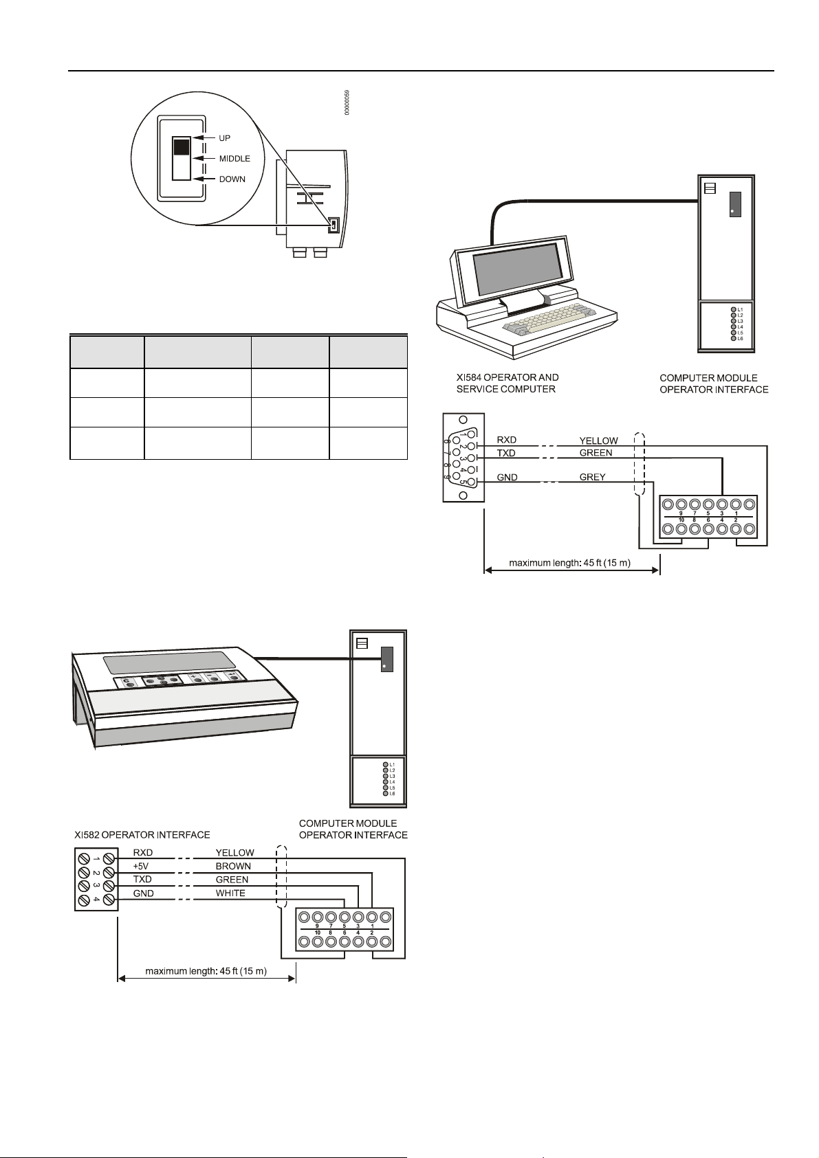
Fig. 84. Excel 500-XCL5010 C-Bus DIP switch location
Table 23. DIP switch settings for C-Bus termination
(Excel 500-XCL5010)
DIP switch Communication Controller Com-
setting speed location patibility
up max. 9.6 Kbaud -
middle max. 76.8 Kbaud
down max. 76.8 Kbaud
middle of XD508,
bus XL20XD508
beginning or XD508,
end of bus XL20XD508
XD505A,
XL20XD
EXCEL 500/600 INSTALLATION INSTRUCTIONS
For connection to the XI584 Operator and Service Computer,
a tailor-made cable is available with plugs on both ends.
— XW567 cable, length 7 ft (2.5m)
NOTE: Modules listed in Compatibility column are used in
Excel 20/100B/500/600 Controllers.
Excel 600 Cable Specifications
For connection to the XI582 Operator Interface, two tailormade cables are available.
— XW564 cable, length 7 ft (2.5 m)
— XW565 cable, length 15 ft (5 m)
Fig. 86. Excel 600 / XI584 cable details
Fig. 85. Excel 500 / XI582 cable details
39 EN1R-1047GE51 R0902
Page 40
EXCEL 500/600 INSTALLATION INSTRUCTIONS
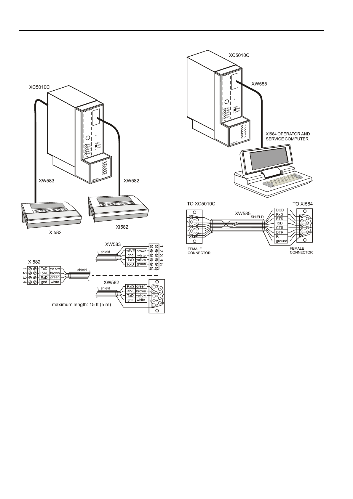
Excel 500 Cable Specifications
The XI582AH Operator Interface can be connected either to
the or the back of the XC5010C.
— XW582 cable, front connection, length 15 ft (5 m)
— XW583 cable, back connection, length 15 ft (5 m)
Fig. 87. Excel 500 / XI582 cables
The XI584 Operator and Service Computer can be connected
to the front of the XC5010C computer module with the
following cable:
— XW585 cable, length 15 ft (5 m)
Fig. 88. Excel 500 / XI584 operator and service computer
cable details
NOTE: You can also use a standard null modem cable.
An adapter cable is needed when the same MMI unit
XI582AH or XI584 is used on a site where there is a mix of
XC5010C and XC6010 CPU modules. Always use the new
cables XW582 and XW585 with the XC5010C CPU module
and the additional adapter cable XW584 for connecting to the
XC6010 CPU module.
EN1R-1047GE51 RR0902 40
Page 41
Excel 500-XCL5010 Cable Specifications
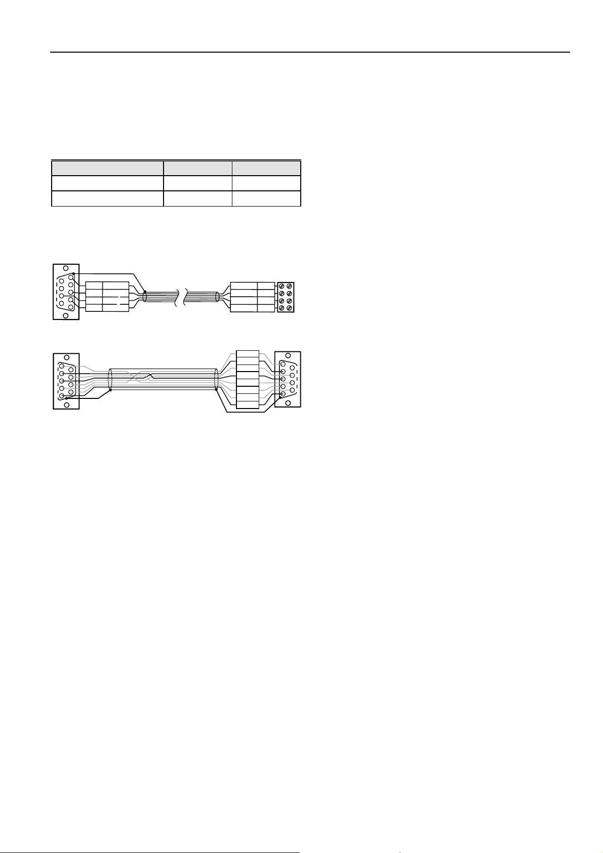
MMI Cables
Ready-made cables with the shield already connected to the
computer module plug end are available for the connection of
external MMIs.
Table 24. Cable specifications
MMI type Cable Length
XI582 (remote MMI) XW582 17 ft (5m)
XI584 (PC-based MMI) XW585 17ft (5m)
For connection to the XI584, a standard null modem cable
may be used.
TO EXCEL 500-XCL5010
5
9
4
8
3
7
2
6
1
T
E
H
I
W
G
N
D
D
T
x
Y
E
O
L
L
+
5
R
x
W
V
E
B
R
O
N
W
D
G
R
E
E
N
XW582
SHIELD
Y
E
L
L
B
R
O
W
G
R
E
E
T
H
I
W
XI582
T
D
x
O
W
V
5
+
E
N
R
N
D
x
G
N
D
E
EXCEL 500/600 INSTALLATION INSTRUCTIONS
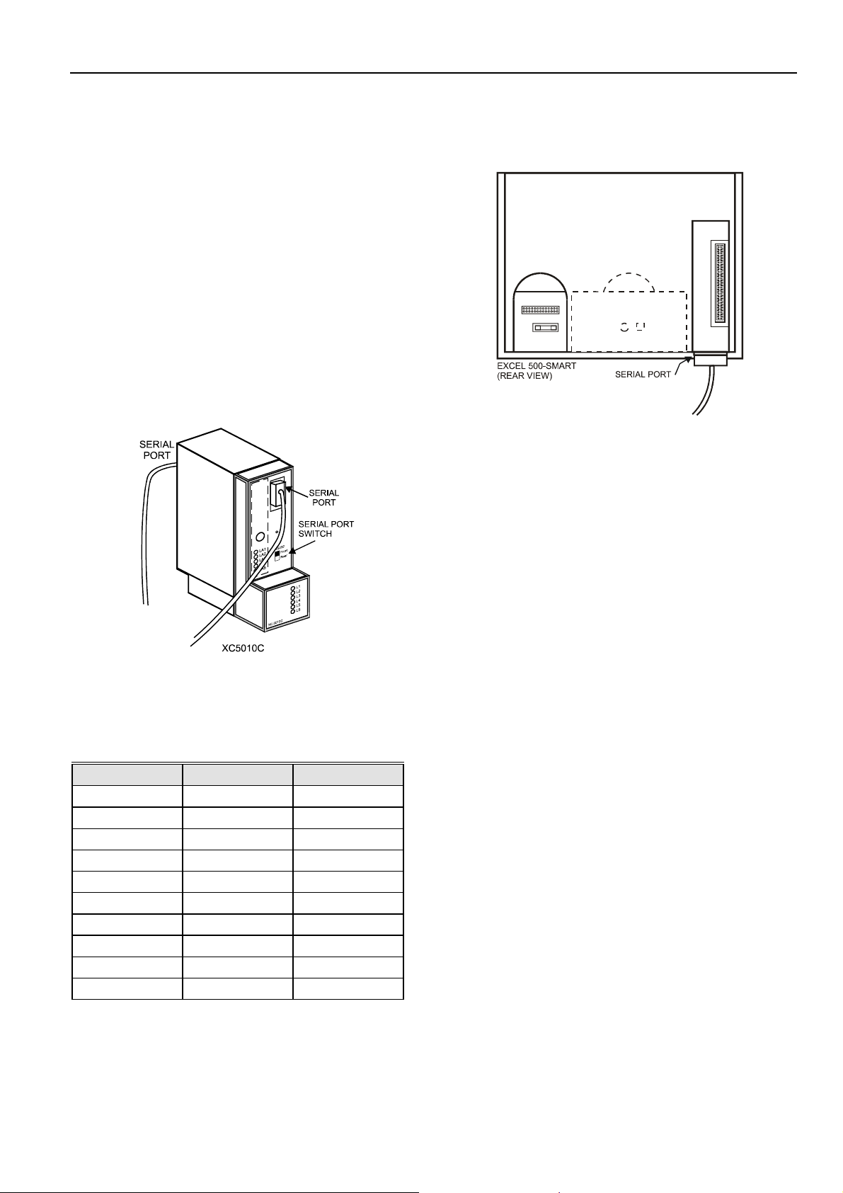
Modem or ISDN Terminal Adapter Connections
For remote communications, a modem or ISDN terminal
adapter can be connected directly to the serial port of the
Excel 500-XCL5010 Controller.
The serial port of the Excel 500-XCL5010 controller accepts a
standard modem cable with a female 9-pin connector. Use
the cable that is supplied with the modem/ISDN terminal
adapter.
The communication speed is 9600 baud by default but can be
set as high as 38.4 Kbaud.
For more details, see section "Remote Communications" on
page 43.
Changing Between MMI and Modem Connection
The Excel 500-XCL5010 will detect when an MMI or
modem/ISDN terminal adapter is connected and will adjust
the communication speed automatically according to the
1
2
preset values. This automatic detection can take up to 5
3
seconds.
4
TO EXCEL 500-XCL5010
XW585
12
3
4
9 678
5
SHIELD
Fig. 89. Excel 500-XCL5010 / MMI cable details
DCD
RxD
RTS
TxD
CTS
DTR
RI
GND
TO XI584
12
3
4
5
9 678
41 EN1R-1047GE51 R0902
Page 42

EXCEL 500/600 INSTALLATION INSTRUCTIONS
Fig. 90. Excel 500 and Excel 600 used together with XI584 and XI582 Operator Interfaces
Fig. 91. XW584 cable details
EN1R-1047GE51 RR0902 42
Page 43
REMOTE COMMUNICATIONS
The following applies to the XC5010C and XCL5010, only.
For remote communications with up to three XBS Building
Centrals, a modem or ISDN terminal adapter can be
connected directly to the serial port of the XC5010C CPU
(either front or rear connection) or the serial port of the
XCL5010.
NOTE: Remote communication via modem or ISDN terminal
adapter requires firmware version V2.1.0 or higher.
NOTE: XBSi building supervisors are not supported for
remote communication.
Modem or ISDN Terminal Adapter
Connections
The front serial port of the XC5010C CPU accepts a standard
modem cable with a female 9-pin connector.
EXCEL 500/600 INSTALLATION INSTRUCTIONS
The serial port of the XCL5010 CPU accepts a standard
modem cable with a female 9-pin connector.
Fig. 93. Serial port location on Excel 500-XCL5010
Use the cable that is supplied with the modem/ISDN terminal
adapter. The communication speed is 9600 baud by default
but can be set as high as 38.4 Kbaud.
NOTE: See section "Serial Port" on page 32, for signals of
serial port.
Modem Requirements
• Modem must support Hayes compatible command set (not
V150 or V151 = Microsoft command set)
• Modem must support alpha-numeric return codes
Fig. 92. Serial port locations on Excel 500
Use the cable that is supplied with the modem/ISDN terminal
adapter. To connect to the terminals of the rear serial port of
the XC5010C, use cable XW571 (length: 6 ft (1.9m)).
Table 25. XW571 Connection
Pin XC5010C RS232 signal Wire color
2 RTS Blue
3 GND White
4 TxD Yellow
5 RxD Green
6 CTS Violet
7 DTR Black
8 (not used) SG White
9 DCD Brown
10 Shield Clear
11 (not used) RI Red
NOTE: Pin numbers shown are for the rear connector of the
XC5010C Computer Module.
• Modem must follow serial baud rate of the CPU
• Modem must support auto-bauding (baud rate fall-back)
• When carrier detect (connect) is reported, the carrier must
be on simultaneously at both modems (on CPU side and
on XBS side) use same modem
• After a switch-ON of the DTR line by the CPU or XBS, the
modem must accept a dial command after 3 seconds
• Modem must answer AT commands in less than 3
seconds
No Set-up for Standard Modem Behavior
If no special modem behavior is required, there is no need to
set up or initialize the modem/ISDN terminal adapter. The
XC5010C/XCL5010 CPU will automatically detect the device
(MMI or modem) attached to the serial port and set the
appropriate communication speed. The controller will also
automatically adapt to alphanumeric return codes used by the
modem. This automatic detection and adjustment can take up
to 5 seconds.
NOTE: It is highly recommended to use a state-of-the-art
modem and leave it in its factory setting.
43
EN1R-1047GE51 R0702
Page 44

EXCEL 500/600 INSTALLATION INSTRUCTIONS
Automatic Baudrate Synchronization
The default communication speed between the
XC5010C/XCL5010 CPU and the local modem/ISDN terminal
adapter is 9600 baud.
The communication speed between the XC5010C/XCL5010
CPU and XBS modems/ISDN terminal adapters is automatically synchronized by the two devices to the highest
speed that both of the devices are capable of. This feature is
called autobauding and is a feature that all state-of-the-art
modems/ISDN terminal adapters provide when left in their
factory default settings.
The communication speed between the XBS and its
modem/ISDN terminal adapter is part of the modem set-up at
the XBS.
Auto / Manual Answer Detection
The XC5010C/XCL5010 CPU will automatically detect
whether the modem/ISDN terminal adapter is initialized in
auto-answer or manu-answer mode, and it will set the modem
to manual answer mode (S0 = 0).
Resetting the Modem
For those cases where it is not clear if the modem to be used
is in its factory setting, the modem can be reset to its factory
setting by using the RESET MODEM command in the Startup sequence or through the HW Config. part of the System
Info. sequence on the MMI. This will allow a quick and easy
modem reset without the need to run the modem set-up
software or the Windows™ terminal program.
The RESET MODEM command causes the following
commands to be sent to the modem:
1. ATZ
executes hardware reset on modem
2. AT&FX3&W
resets modem to factory configuration settings,
configures the modem not to wait for the public phone
system dial tone, and writes this to nonvolatile memory.
Set-up for Special Modem Behavior
If special modem/ISDN terminal adapter behavior is required,
the communication device should be set up according to the
instructions provided with it. This typically involves running a
setup program on a computer with the device connected to
the computer serial port or using the Windows™ terminal
program.
Set-up for In-house Telephone Systems
A common case of special modem behavior is when the
modem is connected to an in-house telephone network
requiring a prefix to be dialed before the destination number
to provide access to the public telephone network. There are
two important aspects of the special initialization of the
modem to consider:
1. Do not wait for the public network dial tone. Typically
the init command ATX3 will trigger the modem to dial
without waiting for a public network dial tone. Save this
modem set-up in the modem EEPROM with the
command AT&W. Check the modem handbook to verify
the correct commands. Note that these commands are
executed automatically with the RESET MODEM
command.
2. Add the prefix required for access to the public
telephone network to the destination telephone number.
Depending on the in-house telephone system, a certain
prefix may have to be added to the destination number
in the XBS system configuration/site definition screen
prior to sending the set-up to the remote Excel 500
controller.
Set-up for Limited Communication Speed
The communication speed of the modem can be fixed to a
lower rate in case of data transmission errors due to telephone line limitations. See the XI581/582 Buswide Operator
Interface User Guide (EN2B-126GE51) for the procedure for
fixing the baud rate.
Troubleshooting
In case of any problems the handbook of the modem or ISDN
terminal adapter must be consulted.
A “Frequently Asked Questions and Troubleshooting”
document is available via the Honeywell Technical Assistance
Center (TAC) or, for Honeywell employees, on the HIVE
under:
Technical Assistance Center/Controllers/Excel 80 and 100
and 500 and 600/ technical literature/modemfaq.doc
or on the Docu Server under:
http://web.ge51.honeywell.de/dep/mc/TAC_Tips/Modem
FAQ.doc
TCP/IP Dial-Up via TCP/IP Modem XM500
The Honeywell TCP/IP modem XM500 allows use of a
TCP/IP network (e.g. Ethernet LAN/WAN networks) to
achieve a dial-up connection between an XBS building
supervisor and an Excel 500 controller. The set-up is identical
to that of a telephone modem connection with the exception
of the additional need for definition of the Ethernet address.
Details can be obtained from the XM500 Product Data
Documentation on the Honeywell Intranet under:
http://web.ge51.honeywell.de/dep/mc/HVAC_Products/Autom
ation_and_Control/CentralPlantControls/ModemInterface/xm500/xm500_pd.zip
GSM Communication (Europe, only)
For communication via the Global System for Mobile
communications (GSM), a Siemens M20 Terminal (cellular
engine) is required and must be connected directly to the
serial port of the Excel 500 controller. The M20T translates
the Excel CPU data received in transparent mode into the
GSM standard. The M20T behaves like a Hayes-compatible
EN1R-1047GE51 RR0902 44
Page 45

EXCEL 500/600 INSTALLATION INSTRUCTIONS
R
C
modem connected to the Excel controller serial port, and it
then transmits via GSM like a cellular (mobile) phone.
NOTE: Communication via GSM requires firmware version
V2.3.0 or higher.
IMPORTANT
With the M20T, data communication is possible only
in 900 MHz GSM networks. GSM networks
operating at 1800 MHz or 1900 MHz are not
supported.
The maximum communication speed is determined by the
current GSM standard, which is 9600 baud. Due to a special
transmission mechanism, the effective communication
throughput is lower than 9600 baud – however this will be
noticeable only when high data volumes are transmitted, e.g.
when application download is performed.
M20T Safety Precautions
CAUTION
Use of the M20 Terminal on-board aircraft is
forbidden. Use of a Cellular Engine in an aircraft, such
as for the purpose of wireless connection of an aircraft
based HVAC system to an XBS central, can endanger
navigation, it interferes with the cellular network and it
is illegal. Failure to comply with this prohibition may
lead to temporary suspension or permanent
cancellation of Cellular Engine services for the person
who disregards this prohibition and/or to legal action
against said person.
address all questions to a doctor or the
manufacturer of the medical device.
• The M20 Terminal shall not be used within wet
environment, such as in public baths.
• If your M20 Terminal, your SIM card or both go
missing, notify your network operator immediately
in order to avoid misuse.
Required Third-Party Equipment
The Siemens M20 Terminal (shown below) is required for
GSM communication. In addition, a 3V Mini SIM card with
personal identification number (PIN) is required for the M20T.
The Mini SIM card, supplied by the GSM Network Provider,
must be released for data communication at 9600 baud.
HANDSET IN TERFACE
MOUNTING HOL ES
TOP
BOTTOM
SIM CARD READE
OPERATING
STATUS LED
CAUTION
Users are advised to NOT use the M20T in
automotive service stations.
Users are reminded of the necessity of complying with
restrictions regarding the use of radio devices in fuel
depots, chemical plants and locations where
explosives are ignited.
Additional precautions are as follows:
• When receiving calls on a public highway, such as
a cooling control system of a refrigeration truck
being called by an XBS central, the M20T is not
permitted to use "warning" devices which causes
the vehicle’s horn to sound or the lights to flash.
• Drivers are advised not to use the handheld
microphone or the telephone handset while their
vehicle is in motion, except in emergencies. Use
the hands-free facility to speak only if it does not
divert your attention from the traffic.
• Operation of the M20T can disrupt the operability
of inadequately protected medical devices. Please
V.24 INTERFACE AND AUDIO
SUB-D SOCKET
POWER SUPPLY
INTERFA
E
FME ANTENNA
CONNECTOR
Fig. 94. Siemens M20 terminal
A separate telephone number is required for data
communication with the same SIM card (one telephone
number for voice communications and one for data).
Mechanical characteristics:
Weight 145 g
Dimensions (max) LxWxH 107.0 x 63.5 x 31.3 mm
Temperature range -20°C to 55°C
Protection-class IP40
Mechanical vibrations Amplitude 7.5mm at
5 to 200 Hz sine
Max. pulse-acceleration 30 g pulse with 18 ms duration
Air humidity 5–98%
Electrical characteristics:
Operating voltage range 8 to 28.8 Vdc, ±5% ripple
Undervoltage/overvoltage
protection: 0 V / 45 V
Power consumption at 12V <200 mA speech mode,
<14 mA idle mode
Max. line-in/out cable length 2 m (e.g. modified NOKIA 2110
for M20T)
45
EN1R-1047GE51 R0702
Page 46

EXCEL 500/600 INSTALLATION INSTRUCTIONS
Protection fuse 1 A, fast blow
Max. RF power 2 W at 900 MHz
Power supply connector 6-pin modular
CE conformity:
• 89/336/EC (EMC guideline)
• 73/23/EC (Low voltage guideline)
• 91/263/EC (Telecommunications devices guideline)
Standards:
• EMC: ETS 300 342-1
• Safety: EN 60950
• GSM network: TBR 19, TBR 20
Serial Cable
For connecting the M20T to the Excel 500 controller, a
standard RS232 cable (9-pin V24 sub-D sockets) is required.
GSM Antenna Requirements
All major suppliers of GSM antennas can supply GSM900
Antennas with FME plugs to connect with the M20 Terminal
for a variety of applications. Some antenna examples are
shown below.
The antenna must satisfy the following electrical
requirements:
Frequency TX 890-915 MHz
Frequency RX 935-960 MHz
Impedance 50 ohms
VSWR TX: max. 1.7:1 installed
VSWR RX: max. 1.9:1 installed
Gain > 1.5 dB referenced to λ/2 dipole
3dB width of cone
vertical: 80°
horizontal: 360°
Max. power: 1 W (cw), 2 W peak; at ambient
temperature of 55°C
Antenna Examples
Fig. 95. Round radiation antenna, magnetic base, 5 DBi
Fig. 96. Directional antenna (YAGI), 12 DBi
Depending on the application and the RF field at the local
site, the GSM antenna may be mounted directly or via cable.
The maximum antenna cable length is 8.0 m (including 20 cm
M20 Terminal-cable)
NOTE: The maximum number of push/pull cycles shall not
exceed 100.
The antenna interface connector of the M20 unit is a FME
connector (of type SMR nano (male)). Hence, the connector
on the GSM antenna or antenna cable has to be of type SMR
nano (female, or use a double female connector in between).
EN1R-1047GE51 RR0902 46
Fig. 97. Round radiation antenna, 6.5 DBi
Fig. 98. Window patch antenna, 2 DBi
Page 47

EXCEL 500/600 INSTALLATION INSTRUCTIONS
GSM Antenna Installation
The maximum antenna cable length is 8.0m (including the 20
cm M20 Terminal cable). Use a cable that is specified by the
supplier of the GSM antenna. Improper cables with
resistances that are too high will reduce the amplification of
the antenna.
• Ideally you should know in which direction the next GSM
station is located in order to position of the antenna
accordingly.
• The easiest way to check the signal quality is to operate a
cellular (mobile) phone at the very place where you want
to place the antenna.
— The cellular phone must operate in the same GSM
network as the M20T.
— Drop-outs in voice communication indicate that the
reception is too weak. The data communication will
never work where you have drop-outs in voice
communication with the cellular phone. The preferred way is to set-up the M20T on a terminal
program and check the reception with the SIEMENS
AT commands – see the M20T handbook.
— An alternative way to verify the signal quality is to
use the terminal program on the CD that is supplied
with the M20T. You will find a special button on it
that allows checking on the signal quality.
• Dipole antennas - e.g. antennas with a magnetic foot -
must sit on metal ground to achieve the specified
amplification. The larger the metal ground, the better.
• The antenna must be mounted vertically, NOT horizontally.
M20 Terminal Set-up
Prior to beginning the set-up, get the M20T manual (or CDROM, if it was delivered with one). Everything is described in
it and you will need it.
IMPORTANT
It is absolutely mandatory to use a serial data line
monitor for the set-up of the M20T. Without such a
device being connected between the serial port of
the PC and the M20T, you will get no information on
the set-up process.
1. Insert the SIM card into the M20T.
2. Connect the serial cable to the M20T and a PC or
laptop.
3. Connect the antenna cable and antenna to the M20T
connector.
4. Start a terminal program, e.g. Windows™
HyperTerminal
5. Connect the power supply to the M20 Terminal and
plug into mains.
The M20T LED will be blinking now.
6. Set terminal program to 19200 baud.
7. Verify the correct operation of the M20T serial interface
by entering: AT.
The M20T will respond: OK.
8. Change the M20T’s baud rate from 19200 (factory
default) to 9600: AT+IPR=9600.
9. Set terminal program back to 9600 baud.
10. Command the M20T to cut the line whenever the DTR
signal is dropped (OFF) or toggled ON/OFF: AT&D2
11. Store setting in nonvolatile memory: AT&W.
12. You may now enter the PIN number or let the Excel
CPU do this. If you want to enter the PIN number now,
enter the PIN with the command AT+CPIN=”xxxx”,
where xxxx represents the PIN number.
• Avoid barriers for the antenna signal. Ideally, within a
range of approximately 3 meters there should not be any
vertical barriers that would block the antenna signal, such
as doors, PCs, cupboards, etc.
• Select the most suitable antenna. Location and mounting
limitations may require that special antennas be used,
such as antennas with higher amplification or directional
antennas.
• Avoid loose contacts. All connections from the M20T to the
antenna must be tight.
• Increase the distance between the antenna and Excel
CPU if you experience electromagnetic interference of the
antenna signal to the CPU. An indication of this might be
that the functioning of the MMI of the CPU is disturbed or
that the outputs behave abnormally.
NOTE: Regarding the PIN entry, the M20T shows the same
behavior as a regular cellular phone, as it uses the
same type of SIM card. This means, for example,
that after 3 false PIN inputs, the SIM card will lock
and need to be released via the “PUK” Personal
Unlocking Key (Master PIN).
Repeated input of the wrong “PUK” (more than 2
false inputs) will destroy the SIM card irrevocably.
13. Once the M20 has accepted the PIN it will log into the
GSM net.
The terminal window will show “OK”.
The M20T LED will be on continuously.
14. Disconnect the serial cable from the PC/laptop and
connect it to the Excel CPU.
15. Verify that the M20T dials out on the telephone number
for data communication, otherwise, its call will not be
recognized by the XBS. The M20T can be forced to do
so by adding the letter <i> to the telephone number,
e.g.<ATDi1234567891234>
47
EN1R-1047GE51 R0702
Page 48

EXCEL 500/600 INSTALLATION INSTRUCTIONS
NOTE: As soon as the PIN is entered into the Excel
controller, the following mechanisms will take place
automatically:
— Cyclical check (once per minute) for existence
of the PIN number in the M20 (AT+CPIN?)
— Sending of PIN number to M20T, if it has lost it.
This guarantees communication will resume
automatically after exchange of the SIM card or
after power to the M20T has been lost.
Deletion of the PIN number or resetting the controller
will stop the above mechanisms.
Verification of the PIN
You can verify the PIN without connecting a terminal program
by following these steps:
1. Connect the XI582AH MMI.
2. Enter PIN.
3. Disconnect the XI582AH MMI.
4. Connect the M20T.
5. Reconnect the XI582AH MMI.
6. View the “PIN” field.
7. If it shows “0”, the PIN was wrong.
8. If it shows “PIN”, the PIN was correct.
Additional information about the M20 terminal may be found
at the following website:
http://www.siemens.de/ic/products/cd/english/index/products/
cellular/m20t.html
By using this Honeywell literature, you agree that Honeywell will have no liability for any damages arising out of your
use or modification to, the literature. You will defend and indemnify Honeywell, its affiliates and subsidiaries, from and
against any liability, cost, or damages, including attorneys’ fees, arising out of, or resulting from, any modification to the
literature by you.
Control Products Control Products Control Products
Honeywell Inc. Honeywell Limited-Honeywell Limitee Honeywell AG
Honeywell Plaza 155 Gordon Baker Road Böblinger Straβe 17
P.O. Box 524 North York, Ontario D-71101 Schönaich
Minneapolis, MN 55408-0524 M2H 3N7 Germany
USA Canada
http://www.honeywell.com http://www.honeywell.c
EN1R-1047GE51 R0902 / 95-7524-3 printed in Germany Subject to change without notice
a ht
tp://europe.hbc.honeywell.co
m
 Loading...