

Page 1
BEFORE INSTALLATION
The ZAPP receiver is capable of exchanging data with the
ZAPP handheld (RT 7070A). Up to eight ZAPP handhelds
may be used in a single system.
IMPORTANT!
ZAPP may be used only in countries where ISM
433MHz band is useable.
Further, it is recommended that devices be kept at
room temperature for at least 24 hours before
applying power to allow any condensation resulting
from low shipping/storage temperatures to
evaporate.
INSTALLATION
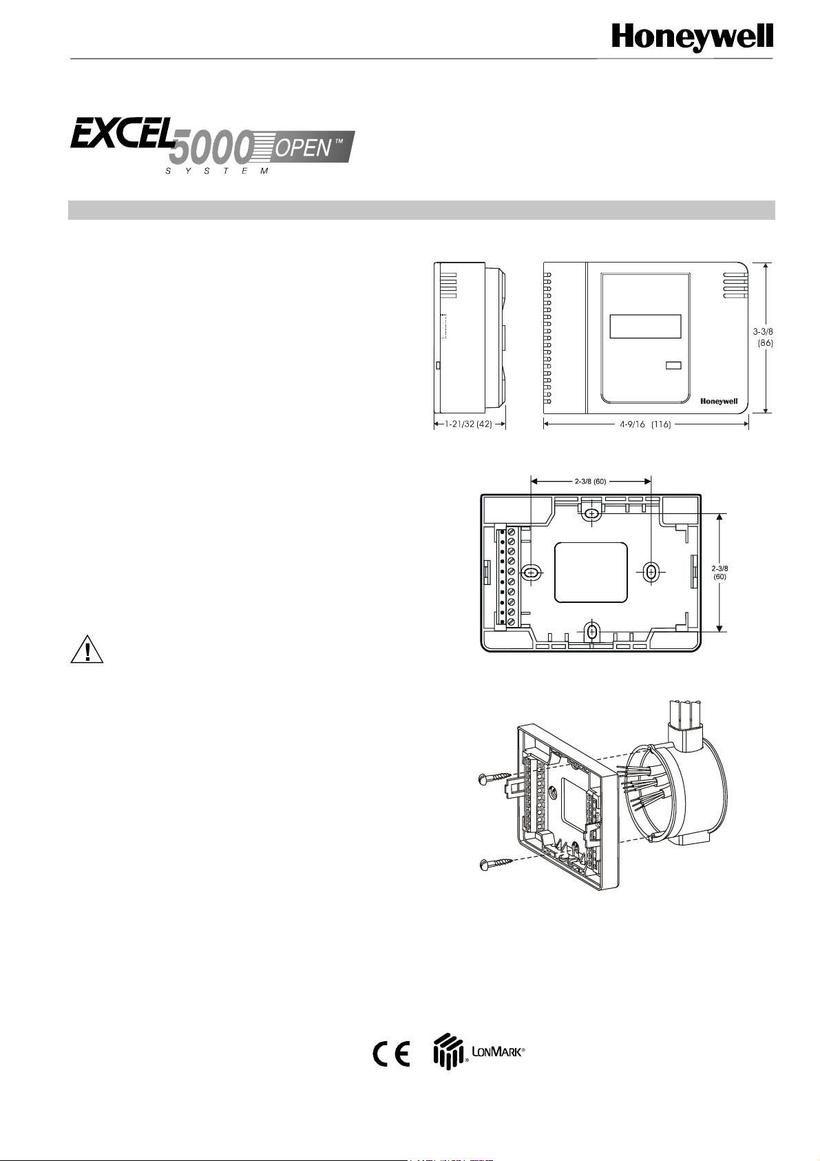
See Fig. 1 for outside dimensions and Fig. 2 for sub-base
mounting dimensions. The ZAPP receiver can be mounted in
any orientation desired on a panel, wall, or onto a standard
wall outlet box (see Fig. 3).
ZAPP
RECEIVER
INSTALLATION INSTRUCTIONS
Fig. 1. ZAPP receiver outside dimensions in inches (mm)
Power
Input power provided must be 24 Vac (±20%), 50 or 60 Hz.
For US installation, power must come from an energy-limited
Class II Power Source (transformers must not exceed 100
VA).
CAUTION
Electrical shock or equipment damage. Turn off
power prior to connecting to or removing connections
from any terminals.
Use the heaviest gauge wire available, up to 14 AWG
(2.5 mm
power wiring.
Communications
Wire the ZAPP communications LONWORKS ® network using
level IV 22 AWG or plenum-rated level IV 22 AWG nonshielded, twisted pair, solid conductor wire.
2),
with a minimum of 18 AWG (1.0 mm2) for all
Fig. 2. Sub-base mounting dimensions
1
2
3
4
5
6
7
8
9
10
Fig. 3. Mounting on wall outlet box
® U.S. Registered Trademark
Copyright © 2002 Honeywell Inc.
All Rights Reserved EN1B-0166GE51 R0502
Page 2
ZAPP utilizes a free topology transceiver (FTT10A) Link
Power compatible L
ONWORKS
®
network that allows daisychain, loop, and star network configurations or any
combination thereof.
Depending upon the L
ONWORKS
®
network configuration
used, one or two termination modules may be required (see
Fig. 4). Different connections to the termination module are
necessary, depending upon whether it is used in a singly- or
doubly-terminated network configuration.
NOTES:
— The L
ONWORKS
®
network is insensitive to polarity,
eliminating installation errors due to miswiring.
— For installations, try to avoid areas of high
electromagnetic noise (EMI).
Range of RF Transmission
Because of ZAPP's radio-frequency characteristics, it is not
possible to exactly define its transmission range.
The transmission range is comparable to that of cordless (not
cellular!) telephones, i.e. about 30 meters inside a building.
5
6
7
8
5
6
7
8
ORANGE
BROWN
TERMINATION
MODULE (209541B)
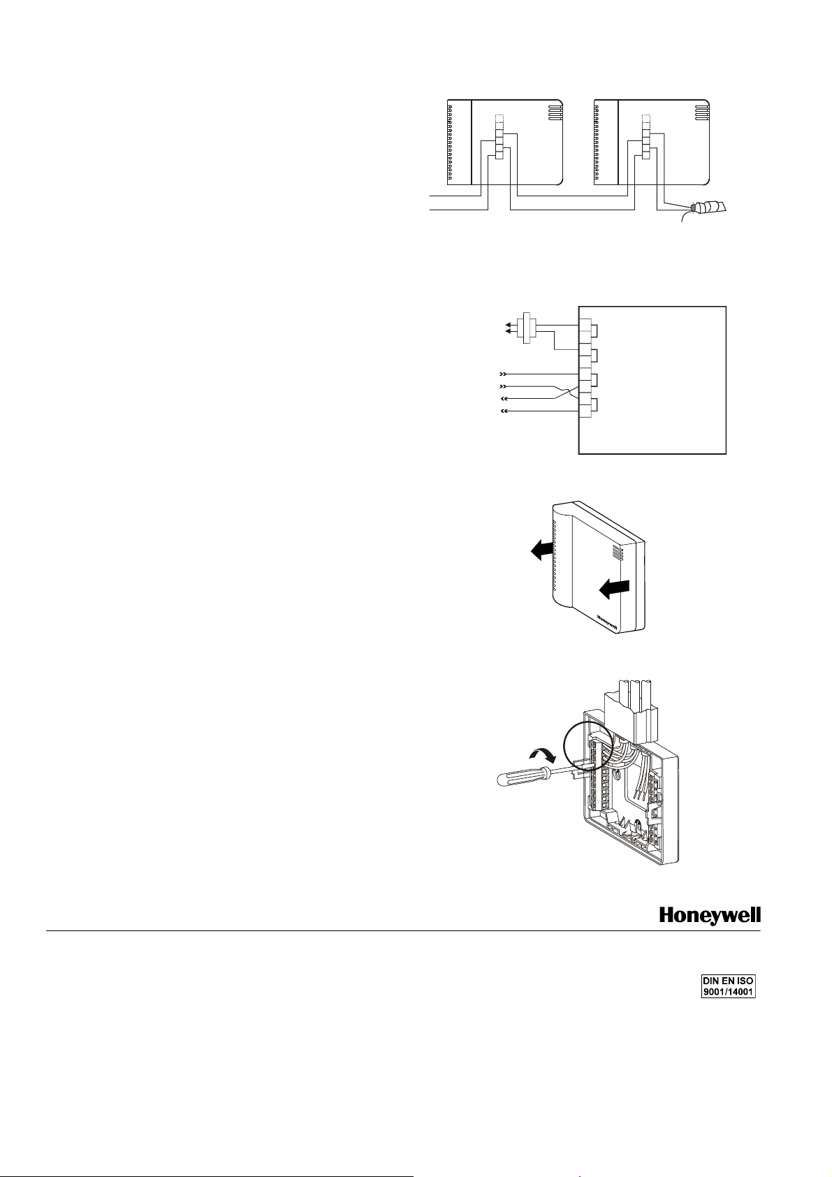
Fig. 4. Termination module connection (daisy-chain
network configuration)
ZAPP RECEIVER
24 VAC
1
120/240 VAC
LONW
ORKS
L
ONWORKS
NETWORK OUT
24 VAC COM
NETWORK IN
2
3
4
5
6
7
8
24 VAC
24 VAC
24 VAC
24 VAC
LonWorks
LonWorks
LonWorks
LonWorks
As a rule of thumb, the signals can travel through one wall
and one ceiling or through two walls.
It is recommended that you always first test ZAPP in the
actual environment in which it is to operate. Use LonMaker or
EXCELON in conjunction with nvoRfState.LastCommand to
verify a successful transmission from the handheld unit to the
receiver.
Wiring Details
Fig. 5 illustrates the terminal assignments of the ZAPP
receiver. Refer to job drawings for specific wiring diagrams.
Connections to the ZAPP receiver are made at an internal
terminal block accessible beneath the front cover. No tools
are required to remove the front cover.
1. Simply pull away the cover from the sub-base as
shown in Fig. 6.
Use a minimum wire size of 20 AWG (0.5 mm
input/output connections. The maximum length of all
input/output cables is 65 ft (20 m).
Wire to the terminal blocks as follows:
1. Strip 1/2 in. (13 mm) insulation from the conductor.
2. Insert the wire in the required terminal location and
tighten the screw to complete the termination.
3. Ensure that the wire entering the terminal block does
not extend above the numbered face of the terminal
block to avoid contact between the wires and the
printed circuit board on the underside of the front
cover (see Fig. 7).
2
) for all
Fig. 5. ZAPP receiver terminal assignments
Fig. 6. Terminal cover removal
1
2
3
4
5
6
7
8
9
10
Fig. 7. Terminal box connections
Control Products Control Products Control Products
Honeywell Inc. Honeywell Limited-Honeywell Limitee Honeywell AG
Honeywell Plaza 155 Gordon Baker Road Böblinger Straβe 17 manufacturing location
P.O. Box 524 North York, Ontario D-71101 Schönaich according to
Minneapolis, MN 55408-0524 M2H 3N7 Germany
USA Canada
http://www.honeywell.com http://www.honeywell.ca http://europe.hbc.honeywell.com
EN1B-0166GE51 R0502
7157 409 printed in Germany Subject to change without notice
 Loading...