

Honeywell EXCEL 5000 User Manual

Control Icons
USER GUIDE
74-5577-33 (US)
EN2B-0184 GE51 R0518 (Europe)
HONEYWELL EXCEL 5000 OPEN SYSTEM

74-5577–33 (US)
EN2B-0184 GE51 R0518 (Europe)
Control Icons
V. 10.08.01
USER GUIDE
Software License Advisory This document supports software that is proprietary to Honeywell Inc. and/or to
third party software vendors. Before software delivery, the end user must
execute a software license agreement that governs software use. Software
license agreement provisions include limiting use of the software to equipment
furnished, limiting copying, pre serv ing con fid enti ality , and pro hibit ing tr an sfer to
a third party. Disclosure, use, or reproduction beyond that permitted in the
license agreement is prohibited.

EXCEL CARE CONTROL ICONS
i 74-5577–33 (US)
EN2B-0184 GE51 R0518 (Europe)
CONTENTS
INTRODUCTION ....................................................................................................................................................................... 9
Applicable Literature ............................................................................................................................................................... 10
Control Icon Operation ........................................................................................................................................................... 11
Control Icon Table ............................................................................................... 12
Control Icon Table (Excel Web / Excel Web II) .................................................... 14
Datapoints ........................................................................................................... 19
ALPHABETIC REFERENCE .................................................................................................................................................... 21
Absolute (Excel Web / Excel Web II) ................................................................... 22
Addition / ADD ..................................................................................................... 22
ADH2 (Excel Web / Excel Web II) ....................................................................... 23
Analog Switch / SWI ............................................................................................ 24
AND (Excel Web / Excel Web II) ......................................................................... 25
Arcus Cosinus (Excel Web / Excel Web II) .......................................................... 25
Arcus Sinus (Excel Web / Excel Web II) .............................................................. 25
Arcus Tangens (Excel Web / Excel Web II) ......................................................... 26
Average / AVR ..................................................................................................... 26
Cascade / CAS .................................................................................................... 27
Cascade Plus / CAS ............................................................................................ 31
Changeover Switch / CHA ................................................................................... 34
Compare 2 (Excel Web II) ................................................................................... 35
Comparison (Excel Web / Excel Web II).............................................................. 35
Cosinus (Excel Web / Excel Web II) .................................................................... 36
Counter (Excel Web / Excel Web II) .................................................................... 36
Cycle / CYC ......................................................................................................... 38
Data Transfer / IDT .............................................................................................. 41
Decimal Places (Excel Web / Excel Web II) ........................................................ 44
Delay (Excel Web / Excel Web II) ........................................................................ 44
Dewpoint (Excel Web / Excel Web II) .................................................................. 45
Differential (Excel Web / Excel Web II) ................................................................ 46
Digital Switch / 2PT / Hysteresis (Excel Web / Excel Web II) .............................. 46
Division (Excel Web / Excel Web II) .................................................................... 50
Duty Cycle / DUC ................................................................................................ 51
Economizer / ECO ............................................................................................... 58
EQL (Excel Web / Excel Web II) .......................................................................... 69
Event Counter / EVC ........................................................................................... 70
Exponential (Excel Web / Excel Web II) .............................................................. 70
Factorial (Excel Web / Excel Web II) ................................................................... 71
Fixed Applications (XFM) .................................................................................... 71
ENHANCED PID ............................................................................................. 73
ENTHALPY ...................................................................................................... 77
FLOW CALCULATION .................................................................................... 78
LEAD-LAG ....................................................................................................... 80
Power Demand Control XFMs ......................................................................... 81
RATIO .............................................................................................................. 88
Totalizer XFM .................................................................................................. 89
UP-DOWN RAMP ............................................................................................ 91
XFM 35 Description ......................................................................................... 92
Priority Groups and their Switching Behavior .............................................. 96
XFM 35 Algorithms ..................................................................................... 97
XFM 35 General Functions ......................................................................... 102
XFM 36-1 Description ...................................................................................... 106
Automatic Load Switch-On after Maximum OFF Time Expiration ............... 110
RM Functions .............................................................................................. 111
XFM 36-1 General Functions ...................................................................... 111
XFM 36-1 Priority Group Assignment ......................................................... 113
XFM 36-1/S/R Switching Behavior .............................................................. 113
XFM 36-1/S Sequential Load Switching ...................................................... 113
XFM 36-1/R Rotational Load Switching ...................................................... 115
HC (Excel Web / Excel Web II) ............................................................................ 117
Heating Curve with Adaptation / HCA ................................................................. 118
Humidity and Enthalpy / H,X ................................................................................ 121
Integral (Excel Web / Excel Web II) ..................................................................... 123

CONTENTS EXCEL CARE CONTROL ICONS
74-5577–33 (US) ii
EN2B-0184 GE51 R0518 (Europe)
J-K Flip Flop (Excel Web / Excel Web II) ............................................................. 123
Last Value (Excel Web / Excel Web II) ................................................................. 124
Linear Converter (Excel Web II) ........................................................................... 124
Limit (Excel Web / Excel Web II) .......................................................................... 125
Ln (Excel Web / Excel Web II) .............................................................................. 126
Logic Counter (Excel Web / Excel Web II) ........................................................... 126
Mathematical Editor / MAT ................................................................................... 126
Connection of the MAT Icon to a Control Icon ................................................. 128
Differential Function (DIFT) Dialog Box ........................................................... 128
Formula Entry Procedure ................................................................................ 130
Integral Function (INTEG) Dialog Box ............................................................. 134
LINEAR Dialog Box ......................................................................................... 136
Polynomial Equation (POL) Dialog Box ........................................................... 138
Maximum / MAX ................................................................................................... 140
Merge (Excel Web / Excel Web II) ....................................................................... 141
Minimum / MIN ..................................................................................................... 142
Monoflop (Excel Web / Excel Web II) ................................................................... 143
Modulo (Excel Web / Excel Web II) ...................................................................... 143
Multi-Switch In (Excel Web / Excel Web II) .......................................................... 144
Multi-Switch Out (Excel Web / Excel Web II)........................................................ 144
Multiplication (Excel Web / Excel Web II) ............................................................. 145
Negate (Excel Web / Excel Web II) ...................................................................... 145
Next Schedule (Eagle) ......................................................................................... 145
Night Purge / NIPU ............................................................................................... 146
NOT (Excel Web / Excel Web II) .......................................................................... 149
Odd Parity (Excel Web / Excel Web II) ................................................................. 149
On-Board DI (Excel Web / Excel Web II) ............................................................. 149
On-Board DO (Excel Web / Excel Web II) ............................................................ 150
On/Off Delay (Excel Web / Excel Web II) ............................................................. 150
Optimum Start/Stop / EOH ................................................................................... 151
Optimum Start/Stop / EOH3 ................................................................................. 165
Optimum Start/Stop Energy Optimized Ventilation / EOV .................................... 182
OR (Excel Web / Excel Web II) ............................................................................ 191
PID Controller / PID .............................................................................................. 191
PID Operation .................................................................................................. 197
PID Plus Controller / PID ...................................................................................... 198
Random (Excel Web / Excel Web II) .................................................................... 205
Ratio / RAMP ....................................................................................................... 205
Read Global Reg. (Excel Web II) ......................................................................... 209
Read Priority (Excel Web II) ................................................................................. 210
Read Priority Value (Excel Web II) ....................................................................... 210
Read / RIA............................................................................................................ 211
Reset Timer (Excel Web / Excel Web II) .............................................................. 214
Round (Excel Web / Excel Web II) ....................................................................... 214
Round down (Excel Web / Excel Web II) ............................................................. 214
Round up (Excel Web / Excel Web II) .................................................................. 215
RS flip-flop (Excel Web / Excel Web II) ................................................................ 215
Sequence / SEQ .................................................................................................. 215
SET (Excel Web / Excel Web II) ........................................................................... 223
Sinus (Excel Web / Excel Web II) ......................................................................... 224
Split (Excel Web / Excel Web II) ........................................................................... 224
Square Root (Excel Web / Excel Web II) ............................................................. 224
Subtract / DIF ....................................................................................................... 225
Switching Table (Excel Web / Excel Web II) ........................................................ 226
Tangens (Excel Web / Excel Web II) .................................................................... 227
Time Counter (Excel Web / Excel Web II) ............................................................ 228
Timer Value (Excel Web / Excel Web II) .............................................................. 228
Truncate (Excel Web / Excel Web II) ................................................................... 228
Tuncos (Excel Web / Excel Web II) ...................................................................... 229
Value Ramp (Excel Web / Excel Web II) .............................................................. 229
Value Ramp2 (Excel Web II) ................................................................................ 229
WIDO (Excel Web / Excel Web II) ........................................................................ 230
Write Global Reg. (Excel Web II) ......................................................................... 231
Write Priority (Excel Web II) ................................................................................. 231
Write / WIA ........................................................................................................... 232
X root Y (Excel Web / Excel Web II) ..................................................................... 237
X^2 (Excel Web / Excel Web II) ........................................................................... 237
X^Y (Excel Web / Excel Web II) ........................................................................... 237

EXCEL CARE CONTROL ICONS CONTENTS
iii 74-5577–33 (US)
EN0B-0184 GE51 R0518 (Europe)
XOR Table (Excel Web / Excel Web II) ............................................................... 237
Zero Energy Band / ZEB ..................................................................................... 238
Examples .................................................................................................................................................................................. 244
Attenuator ............................................................................................................ 246
Average Value Calculation .................................................................................. 247
Floating Limits and Alarm Suppression ............................................................... 251
Operating Pump Switchover ................................................................................ 257
Optimized Start/Stop ........................................................................................... 261
Positioning Signal Limitation ................................................................................ 262
Setpoint Adjustments .......................................................................................... 265
System Regulation .............................................................................................. 268
Trend Buffer Control ............................................................................................ 270
Appendix A: Parameter List Description ............................................................................................................................... 273
Appendix B: Startup User Address........................................................................................................................................ 276
Index ......................................................................................................................................................................................... 280


EXCEL CARE CONTROL ICONS
9 74-5577–33 (US)
EN2B-0184 GE51 R0518 (Europe)
INTRODUCTION
Purpose This manual provides descriptions and application examples for control icons in
Excel Computer Aided Regulation Engineering (CARE) software. You use control
icons in the CARE Control Strategy function.
The control strategy for a plant consists of control loops that monitor the
environment and adjust equipment oper atio n to mainta in co mfort levels. For
example, a control loop for an air handling system can turn on a return air fan when
discharge air temperature in the return air duct is greater than or equal to 68F (20C).
Control loops consist of a series of “control icons” that dictate a sequence of events.
Control icons provide preprogrammed functions and algorithms to implement
sequences of control in a plant schematic. Examples of control icons include a
Proportional-Integral-Derivative (PID) function and a Maximum function (MAX).
Assumptions This manual assumes you are familiar with the CARE process, especially the control
strategy and switching logic functions. See Excel CARE User Guide 74-5587 (US) /
EN2B-0182 ( Europe) for details and procedures for the control strategy and
switching logic functions.
Temperature Differentials In the English measurement system, degrees Fahrenheit (F) usually represent both
the temperature measure and the differential measure. Dialog boxes shown in this
manual represent temperatures as °F and differentials as F Deg.
Manual Organization This manual contains the following chapters:
This Introduction lists other technical literature related to control icons, describes the
dialog boxes related to control icon operation, and provides a table that summarizes
the available control icons.
The Alphabetic Reference chapter describes each control icon. The beginning of
the chapter summarizes the type of information provided for each icon.
The Examples chapter describes applications that combine more than one control
icon to perform functions. These examples are in addition to the individual examples
for each icon in the Alphabetic Reference chapter.
Appendix A: Parameter List Description provides information about the parameter
list file generated by CARE when a plant is translated. This file documents the
parameters used in the control icons and switching logic tables. It is useful during
plant testing.
Appendix B: STARTUP User Address describes how the STARTUP user address
works and how to use it in control applications.

INTRODUCTION EXCEL CARE CONTROL ICONS
74-5577–33 (US) 10
EN2B-0184 GE51 R0518 (Europe)
APPLICABLE LITERATURE
Form No. Title
74-5587 (US) Excel CARE User Guide
EN2B-0182 (Europe) Detailed description of Excel CARE software
74-3556 (US) Excel Live CARE User Guide
EN2B-0183 (Europe) Instructions for using Live CARE software to access controller files on-line and
simulate operation
EN2B-162 RACL Editor User Guide
Graphical Editor for creation oft strategy logic programs for Excel 500 controllers.
74-3594 (US) ASPECD Editor User Guide
EN2B-0185 (Europe) Provides functions to modify the user interface for Excel Operator Terminals.
EXCEL CARE CONTROL ICONS INTRODUCTION
11 74-5577–33 (US)
EN2B-0184 GE51 R0518 (Europe)
CONTROL ICON OPERATION
Each control icon has an I/O dialog box that defines its input(s) and output(s). In
addition, some control icons have an internal parameters dialog box that defines
parameter values that govern the function of the control icon.
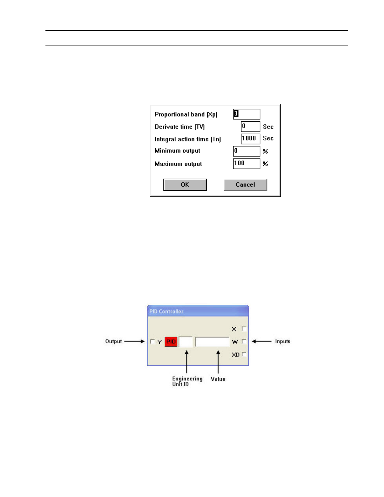
Internal Parameters Dialog Box When you first place a control icon in the Control Strategy work space, the internal
parameters dialog box, if any, displays. For example, for the PID icon, the following
internal parameters dialog box displays:
There are always default values for the parameters. You can change any of the
default values, as desired.
If you click Cancel, the dialog box closes and software does NOT place the control
icon in the control strategy.
You can redisplay the internal parameters dialog box at any time by clicking the
right-hand mouse button while the cursor is over the control icon in the control
strategy.
I/O Dialog Box After you place the control icon (and close the internal parameters dialog box, if
any), you can click the icon once (left-hand mouse button) to display the I/O dialog
box. This dialog box always shows output variables on the left, the control icon in
red, and input variables on the right.
For example, the PID icon displays the following dialog box:
You need to connect the Y, X, and W variables to either physical points,
pseudopoints, and/or other control icons. Variables on the left (Y in this case) are
always outputs. Variables on the right (X and W in this case) are always inputs. The
icon descriptions in the Alphabetic Reference chapter define the types of connection
that are valid for each variable.
INTRODUCTION EXCEL CARE CONTROL ICONS
74-5577–33 (US) 12
EN2B-0184 GE51 R0518 (Europe)
The two blank rectangles in the dialog box are editing fields where you can enter
values instead of point or icon connections. For example, in the PID dialog box, you
can type an engineering unit table ID and value for the W variable, instead of
connecting W to a point or control icon. For engineering unit, enter the
corresponding index number. Appendix E: Engineering Units in Excel CARE User
Guide 74-5587 (US) / EN2B-0182 (Europe) lists engineering units and their index
numbers.
If a variable does not have editing fields next to it, you cannot type values for a
connection; you must connect it to another icon or a point.
See Also ⇒ Excel CARE User Guide 74-5587 (US) / EN2B-0182 (Europe), Control Strategy
chapter, for procedures to place and connect control icons
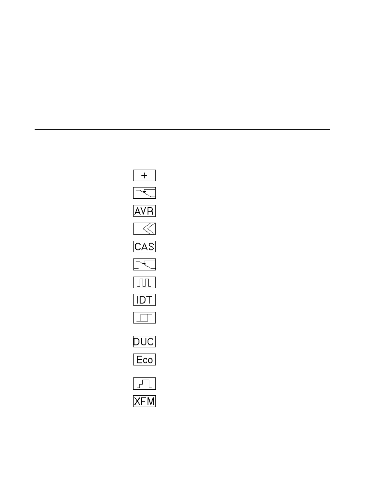
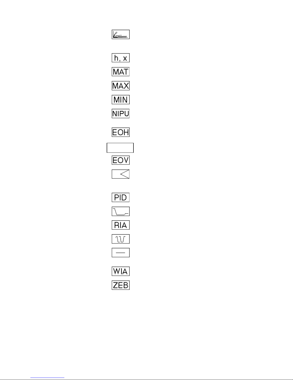
Control Icon Table
This chapter lists icons alphabetically by function name and includes function
names, symbols, and short descriptions. Function name is usually the same as the
icon name. There are exceptions such as 2PT which is functionally a Digital Switch.
Function Name
Control Icon
Icon Name
Description
Add
ADD
Sum multiple analog input values (2
through 6).
Analog Switch
SWI
Switch an analog value depending on a
digital value (for example, if digital is 0,
analog is 2; if digital is 1, analog is 1).
Average
AVR
Calculate the average of multiple analog
inputs (2 through 6).
Cascade
CAS
Cascade controller that acts as a PI
controller with a master and cascade
controller.
Cascade (with additional
digital input and
parameter registers)
CAS
Same as previously defined Cascade
controller with the addition of a digital input
and two parameter registers.
Changeover Switch
CHA
Depending on the value of a digital input,
transmit an analog input value by way of
one of two analog outputs.
Cycle
CYC
Establish cyclical operation.
Data Transfer
IDT
Transfer a value from one control icon to
other icons or points.
Digital Switch
2PT
On/off controller that transmits a digital
status depending on two analog values
(one is a controlled variable; the other, a
reference variable).
Duty Cycle
DUC
Switch HVAC systems on and off at
variable intervals to save energy while
maintaining room conditions.
Economizer
ECO
Determine the most economical system
operation for full and partial air
conditioning systems.
Event Counter
EVC
Event counter.
Fixed Applications
XFM
Fixed applications that can combine with
other submodules or points.
EXCEL CARE CONTROL ICONS INTRODUCTION
13 74-5577–33 (US)
EN2B-0184 GE51 R0518 (Europe)
Function Name
Control Icon
Icon Name
Description
Heating Curve with
Adaptation
HCA
Use a heating curve to calculate discharge
air temperature setpoint from the room
temperature setpoint and outdoor air
temperature.
Humidity and Enthalpy
H,X
Calculate enthalpy and absolute humidity.
Mathematical Editor
MAT
Mathematical editor to modify inputs to
other control icons.
Maximum
MAX
Select the highest value among analog
inputs (2 through 6).
Minimum
MIN
Select the lowest value among analog
inputs (2 through 6).
Night Purge
NIPU
Use cold outdoor air during non-working
(nighttime) hours to precondition room
space and save energy costs.
Optimum Start/Stop
EOH
Calculate optimized values for starting and
stopping heating system.
Optimum Start/Stop
EOH3
EOH3
Calculate optimized values for starting and
stopping the heating plant and for the
supply water setpoint.
Optimum Start/Stop
Energy Optimized
Ventilation
EOV
Calculate optimized values for starting and
stopping air conditioning plant s.
PID
PID
Proportional-Integral-Derivative controller
that regulates an analog output based on
two analog values (one is a controlled
variable; the other, a reference variable.)
PID (with integration time
parameter)
PID
Same as previously defined PID with the
addition of an integration time parameter.
Ratio
RAMP
Limit the variation in room temperature
over time (“ramp” function).
Read
RIA
Read an attribute of a user address.
Sequence
SEQ
Sequence from one to three analog
outputs dependent on an analog input.
Subtract
DIF
Determine the difference between multiple
analog input values
(2 to 6; X1 - (X2 + X3 + .. . X6)).
Write
WIA
Write to an attribute of a user address.
Zero Energy Band
ZEB
Determine setpoints to maintain a
predetermined comfort band divided into
heating, cooling, and zero energy bands.
EOH3

INTRODUCTION EXCEL CARE CONTROL ICONS
74-5577–33 (US) 14
EN2B-0184 GE51 R0518 (Europe)
Control Icon Table (Excel Web / Excel Web II)
This chapter lists icons alphabetically by function name and includes function
names, the previous function name, in which folder it can be found, and short
descriptions. Function name is usually the same as the icon name.
Function Name
Previous Function name
Folder
Description
Absolute
Arithmetic
Returns the absolute value.
Addition
Add
Arithmetic
Sum up the input values.
ADH2
ADH2
Legacy XL500
Legacy RACL function: Adapts the slope S of
the heating curve for the determination of the
flow temperature setpoint to the building
characteristics.
AND
Logic
AND output becomes TRUE(1) if all inputs
are TRUE(1). NAND output is the inverted
AND output.
Arcus Cosinus
Arithmetic
Calculates the arcus cosinus function of X.
Arcus Sinus
Arithmetic
Calculates the arcus sinus function of X.
Arcus Tangems
Arithmetic
Calculates the arcus tangens function of X.
Average
AVR
Arithmetic
Calculates the average of input values.
CAS Plus
Cascade controller
Controller
Cascade controller that acts as a PI
controller with a master and cascade
controller.
Compare2
(Excel Web II with OS
3.01.00 or higher only)
Comparison
Compares two analog inputs (A and B).
Comparison
Comparison
Compares input A and B.
Cosinus
Arithmetic
Calculate the cosinus function of X in rad.
Counter
Misc
Increments the output Y by 1 when input "X"
changes from 0 to 1. The counter is set to 0,
when "Reset" input becomes TRUE (1).
Cycle
Cyclic timer
Timer
Outputs an alternating value.
Decimal Places
Arithmetic
Returns the decimal places value of the input
(3.175 => 0.175).
Delay
Misc
Switch-on delay of input A to Y. if input "A" is
unequal to "B" within delay time, then Alarm
output = TRUE (1).
Dewpoint
Misc
Calculates the dewpoint temperature from
the absol ute humidity.

EXCEL CARE CONTROL ICONS INTRODUCTION
15 74-5577–33 (US)
EN2B-0184 GE51 R0518 (Europe)
Function Name
Previous Function name
Folder
Description
Differential
Controller
Calculates the derivative output signal, which
changes in proportion to changes of the input
signal. Y = 0 if the input is unchanged since
the last cycle. Y > 0 if the deviation is
increasing. Y < 0 if the deviation is
decreasing.
Division
Arithmetic
Divides input A by input B.
Duty Cycle
Duty cycling
Energy management
Switches HVAC systems alternating on and
off to save energy.
ECO
Economy
Legacy XL500
Legacy RACL function: Decide on the most
economical system operation for full and
partial air conditioning systems.
Economy
Energy management
Decide on the most economical system
operation for full and partial air conditioni ng
systems.
Enthalpy
Enthalpy
Misc
Calculate enthalpy (Ent) and absolute
humidity (HAbs) as a function of air
temperature, relative air humidity, and air
pressure. Use Enthalpy with the Economy
function.
EOH
Optimized heating
Energy management
Calculate optimized values for starting and
stopping the heating plant and for the supply
water setpoint.
EOH3
Optimized Start/Stop
Energy management
Calculate optimized values for starting and
stopping the heating plant and for the supply
water setpoint.
EOV
Optimized ventilation
Energy management
Calculate optimized values for starting and
stopping air conditioning systems. Syst em s
should start at the latest possible time and
should stop as soon as possible to save
energy.
EQL
EQL
Legacy XL500
Legacy RACL function: Compares "Comp"
input with all other inputs. If at least one input
is equal to the "Comp" input, the output is set
to TRUE (1).
Exponential
Arithmetic
Calculates the exponential.
Factorial
Arithmetic
Calculates the factorial (5! = 1*2*3*4*5).
HC
HC
Legacy XL500
Legacy RACL function: Calculates an output
according to a user-defi ned he ating
compensation curve.
HCA
Heating curve
Energy management
Calculates an output according to a user-
defined and adaptable heating compensation
curve.
Hysteresis
Digital Switch (2PT)
Controller
On/off controller that generates a digital
output depending on the deviation of the
controlled variable from the reference
variable. Y1 = 1 if X >= W, Y1 = 0 if X < W –
Hysteresis. Y2 = 1 if X <= W, Y2 = 0 if X > W
+ Hysteresis.

INTRODUCTION EXCEL CARE CONTROL ICONS
74-5577–33 (US) 16
EN2B-0184 GE51 R0518 (Europe)
Function Name
Previous Function name
Folder
Description
IDT
IDT
Misc
Copies the input to all outputs.
Integral
Controller
Calculate the integral (sum) of the input
signal.
J-K flip-flop
(Excel Web II with OS
3.01.00 or higher only)
Misc
Toggles an output depending to the set, clear
command and clock conditions
Last Value
Misc
Provides the current value and the value of
the last control cycle.
Limit
Comparison
Limits input X to a range between minimum
and maximum.
LIN
LINEAR
Legacy XL500
Legacy RACL function: Calculates the linear
product of the inputs.
Linear converter
(Excel Web II with OS
3.01.00 or higher only)
Misc
Converts an input value within definable
limits to an output value
Ln
Arithmetic
Calculates the natural logarithm.
Logic Counter
Logic
Compares binary values. Returns in output
N(1) the number of TRUE(1) values and in
output N(0) the number of FALSE(0) values.
Maximum
Max
Comparison
Returns the highest value of all inputs.
Merge
Misc
Merges multiple inputs to a combined output.
Result for 4 inputs: Y = X1 + X2*P1 +
X3*P1*P2 + X4*P1*P2*P3
Minimum
Min
Comparison
Returns the lowest value of all inputs.
Modulo
Arithmetic
Calculates the remainder of the division A by
B.
Monoflop
Timer
Sets the output to TRUE (1) for the time
defined in the parameter "signal time".
Multiplication
Arithmetic
Multiplies the input values.
Multi-Switch In
Misc
Conditional Switch. Switches the value of a
specified input to the output, depending on
the "Sel X" input.
Multi-Switch Out
Misc
X input is copied to the output selected by
the "Sel Y" input. The parameter defines if
the other outputs are left unchanged or set to
0.
Negate
Arithmetic
Negates the analog input value
mathematically.
Next Schedule
(Excel Web II with OS
3.02.00 or higher only)
Misc
Reads the next scheduled value and the time
until the value changes from the schedule
Night Purge
Energy management
Starts and stops ventilation systems to
precondition rooms when cold outside air is
available during nighttime.
NOT
Logic
Negates the binary input value.

EXCEL CARE CONTROL ICONS INTRODUCTION
17 74-5577–33 (US)
EN2B-0184 GE51 R0518 (Europe)
Function Name
Previous Function name
Folder
Description
Odd Parity
Logic
Compares binary values and returns TRUE
(1), if the number of TRUE (1) elements are
odd.
On-Board DI
Misc
Read on-board digital input.
On-Board DO
Misc
Write on-board digital output.
On/Off Delay
Timer
Switch On- and Off delay of input A to output
Y.
OR
Logic
OR output becomes TRUE(1) if at least one
input is TRUE(1). NOR output is the inverted
OR output.
PID
PID controller
Legacy XL500
Legacy RACL function: PID-Controller that
generates a signal depending on the
deviation of the controlled variable from the
reference variable.
PID Plus
PID controller
Controller
PID-Controller that generates a signal
depending on the deviation of the controlled
variable from the reference variable.
POL
POLYNOMIAL
Legacy XL500
Legacy RACL function: Calculates the
polynomial.
Ramp
Misc
Calculates the output value in relation to the
input, depending on a pre-defined graph.
Random
Misc
Returns a random value in a range between
lower and upper limit.
Read Global
Req.
(Excel Web II with OS
3.00.00 or higher only)
Misc
Reads values from global registers
Read Priority
(Excel Web II with OS
3.01.00 or higher only)
Misc
Returns the value of the highest valid priority
in the priority array
Read Priority
Value
(Excel Web II with OS
3.02.00 or higher only)
Misc
Reads the selected priority of the datapoint
Reset Timer
Timer
Resets the timer of a "Timer value" function.
Round
Arithmetic
Rounds the input value to the next integer
value.
Round down
Arithmetic
Rounds the input value down to the next
integer value (3.1 => 3, -3.1 => -4).
Round up
Arithmetic
Rounds the input value up to the next integer
value (3.1 => 4, -3.1 => -3).
RS flip-flop
Misc
Sets the output to TRUE(1) if the "SET" input
is TRUE(1) until the "RESET" input becomes
TRUE(1).
SET
SET
Legacy XL500
Legacy RACL function: Set the output
depending on the compar ison of the inputs .
Y=FALSE(0) if A < B Y=TRUE(1) if A > B Y is
not changed if A = B.
Sequence
Misc
Calculates three output values in relation to
the input, depending on pre-defined graphs.

INTRODUCTION EXCEL CARE CONTROL ICONS
74-5577–33 (US) 18
EN2B-0184 GE51 R0518 (Europe)
Function Name
Previous Function name
Folder
Description
Sinus
Arithmetic
Calculate the sinus function of X in rad.
Split
Misc
Splits the input into multiple outputs. Result
for a split into 3 outputs: Y3 = (((X-Y1) / P1) Y2) / P2) modulo P3.
Square root
Arithmetic
Calculates the square root.
Subtraction
Minus
Arithmetic
Subtracts the sum of S inputs from the input
value M.
Switching Table
Logic
Switching logic module
Time Counter
Timer
Counts the runtime of the input signal.
Timer Value
RTIM
Timer
Legacy RACL function "RTIM": Counts the
time in seconds. Can be reset by the "Reset
Timer" function.
Truncate
Arithmetic
Truncates the decimal places (3.1 => 3, -3.1
=> -3).
Tuncos
Misc
Provides time until next change of state
information from schedule for the connected
input.
Value Ramp
Misc
Defines the slope by which the output will
follow the input.
Value Ramp2
(Excel Web II with OS
3.00.00 or higher only)
Misc
Defines the slope by which the output will
follow the input.
WIDO
Legacy XL500
Legacy RACL function: Checks if the input
value is within the range between minimum
and maximum.
Write Global
Reg.
(Excel Web II with OS
3.00.00 or higher only)
Misc
Writes a value to a global register.
Write Priority
(Excel Web II with OS
3.00.00 or higher only)
Misc
Write the value of an input with a defined
priority to an output which must be connected
with the present value of a datapoint.
X root Y
Arithmetic
Calculates X to the root of Y.
X^2
Arithmetic
Calculates X * X.
X^Y
Arithmetic
Calculates X to the power of Y.
XOR Table
Logic
XOR output becomes TRUE (1) if exactly
one input is TRUE(1). XNOR output is the
inverted XOR output.
ZEB
Zero Energy Band
Energy management
Divides a specified range into Heating range,
Zero energy band and Cooling range.
EXCEL CARE CONTROL ICONS INTRODUCTION
19 74-5577–33 (US)
EN2B-0184 GE51 R0518 (Europe)
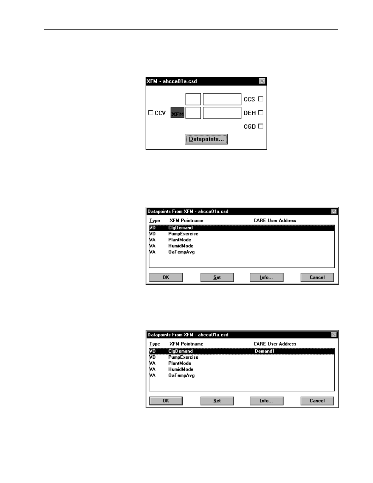
Datapoints
Datapoints Datapoints are a technique of transferring information between XFMs when there
are not enough of the regular inputs and outputs. Datapoints are pseudopoints that
can be written to or read by other XFMs. Create datapoint points by clicking on the
Datapoint button after the XFM has been displayed.
The following figure shows how two XFMs could be wired by a datapoint.
A pseudo digital point Demand1 connects to both XFM 1 and XFM 2 by the use of
datapoints.
After clicking on the datapoint button the following screen appears:
There are two methods of creating the datapoints. One method is by clicking the Set
command to automatically create the pseudopoints with the user address as shown
in the dialog box. The other method is to click an existing point (pseudo or physical)
and then click the point in the dialog box, such as ClgDemand. This selection
locates the subject user address (Demand1) next to the desired datapoint. To
connect the datapoint to that user address click OK.

INTRODUCTION EXCEL CARE CONTROL ICONS
74-5577–33 (US) 20
EN2B-0184 GE51 R0518 (Europe)
For detailed information see XFMs section in the CONTROL STRATEGY chapter of
the CARE USER GUIDE.

EXCEL CARE CONROL ICONS
21 74-5577–28 (US)
EN2B-0184 GE51 R1114 (Europe)
ALPHABETIC REFERENCE
Chapter Contents This chapter describes each control icon as follows:
Function Statement of control icon purpose.
Formula Formula related to icon, if any.
I/O Dialog Box Reproduction of the I/O dialog box that displays in the control
strategy work space for selection of control icon inputs and
outputs.
Inputs Description of required inputs.
Outputs Description of required outputs.
Internal
Parameters Description of the icon’s internal parameters dialog box that
xdisplays for entry of the parameters in the Control strategy work
space. Not all control icons have an internal parameters dialog
box.
Parameter
Number
Descriptions Parameter number assignments. Parameters are identified with
a P and a number, for example, P3, P4. The parameter list file
generated during CARE translation documents control icon
parameters and references them via these numbers. See
Appendix A: Parameter List Description for more information
about the list file.
Note that parameters 1 and 2 are reserved for system use.
Therefore, all parameters described for the control icons start at
number 3.
Operation Some icons have an operation section that details special steps
or provides a functional description of the icon.
Example(s) Sample application(s) of icon.
See Also ⇒ Control Icon Operation in the Introduction chapter for a general description of the I/O
dialog box and the internal parameters dialog box
Examples chapter for descriptions of applications that use multiple icons

ALPHABETIC REFERENCE EXCEL CARE CONTROL ICONS
74-5577–33 (US) 22
EN2B-0184 GE51 R0518 (Europe)
Absolute (Excel Web / Excel Web II)
Function Returns the absolute value and the algebraic sign of an analog value.
I/O Dialog Box
Input One analog input.
Output One analog output (Abs = Absolute value of input)
One digital output (Sign = sign (TRUE(1) if input is negative).
Internal Parameters None.
Addition / ADD
Function Sum multiple analog input values.
I/O Dialog Box
Excel Web / Excel Web II
Inputs Two through six analog inputs (X1 through X6).
You can enter the first input as a parameter (engineering unit index number and
value).
Two through thirty two analog inputs (1 through 32, Excel Web / Excel Web II).
Output One analog output (Y).
EXCEL CARE CONTROL ICONS ALPHABETIC REFERENCE
23 74-5577–33 (US)
EN2B-0184 GE51 R0518 (Europe)
Internal Parameters None.
Example See the Examples chapter for a description of how to use the ADD icon in a floating
limits and alarm suppression applicat ion.
Also see the Data Transfer (IDT) section for examples that show how to use ADD
with IDT.
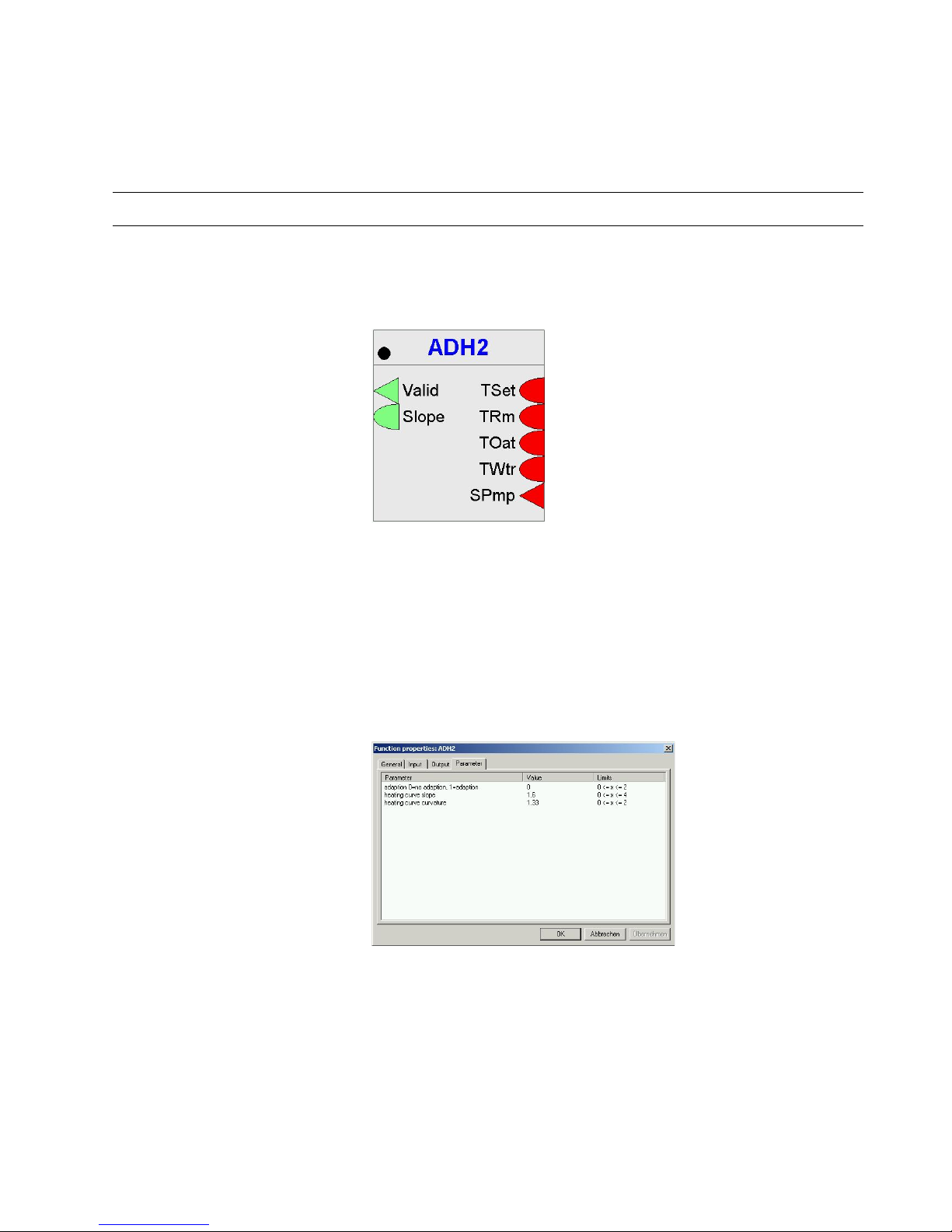
ADH2 (Excel Web / Excel Web II)
Function Legacy RACL function: Calculates the slope S of the heating curve for the
determination of the flow temperature setpoint option to adapt the slope to the
building characteristics.
I/O Dialog Box
Inputs Five inputs where:
TSet = room temperature setpoint
TRm = room temperature
TOat = outside air temperature (req. with adaptation)
TWtr = supply water temperature (req. with adaptation)
SPmp = heating pump status (req. with adaptation)
Outputs Two outputs where:
Valid = slope value validity (0=invalid, 1=valid)
Valid means the slope value is in a possible relation to the inputs, e.g. values below
the freezing point may be impossible.
Slope = calculated slope value
Internal Parameters
Parameter Description P1 Adaptation (0 = no adaptation, 1 = adaptation) with default = 0 and a limit
of 0 < = x < = 1.
P2 Heating curve slope with default = 1, 6 and a limit of 0 < = x < = 4.
P3 Heating curve curvature with default = 1,33 and a limit of 0 < = x < = 2.
ALPHABETIC REFERENCE EXCEL CARE CONTROL ICONS
74-5577–33 (US) 24
EN2B-0184 GE51 R0518 (Europe)
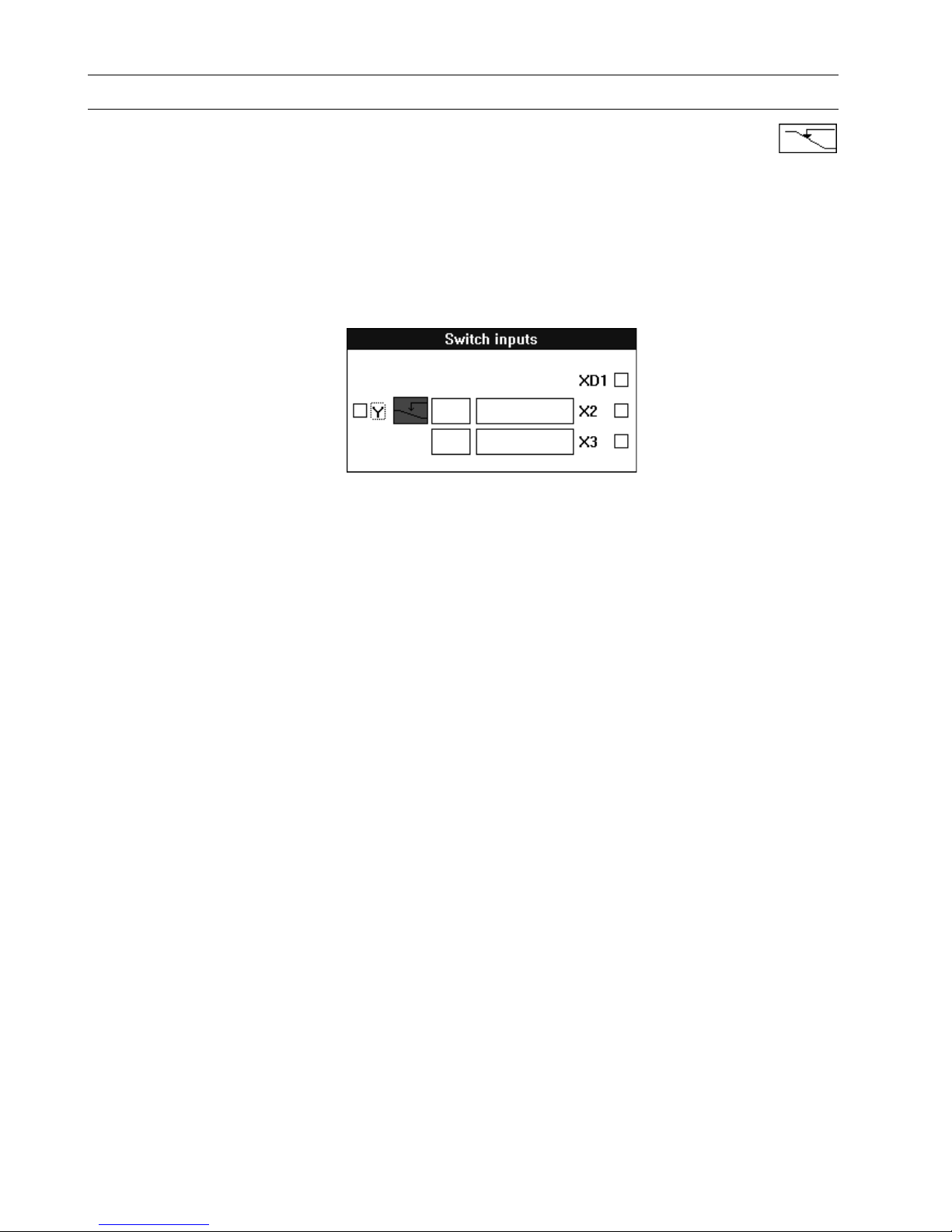
Analog Switch / SWI
Function Switch an analog value depending on a digital value.
For example:
If XD1 = 1, set output Y to X2.
If XD1 = 0, set output Y to X3.
Formula Y = X2, if XD1 = 1.
Y = X3, if XD1 = 0.
I/O Dialog Box
Inputs One digital input (XD1).
Two analog inputs (X2 and X3).
You can enter the two analog inputs as parameters (engineering unit index number
and value for each parameter).
Output One analog output (Y).
Internal Parameters None.
Parameter Number
Descriptions P3 X2 if X2 is not connected with a point.
P4 X3 if X3 is not connected with a point. If X2 is connected with a point, X3 is
numbered parameter 4.
Example See the Examples chapter in this manual for applications that use the SWI control
icon.
Also see the Digital Conversion note in the Mathematical Editor (MAT) section. You
can use SWI to convert a digital point to analog values for use in a mathematical
formula.
EXCEL CARE CONTROL ICONS ALPHABETIC REFERENCE
25 74-5577–33 (US)
EN2B-0184 GE51 R0518 (Europe)
AND (Excel Web / Excel Web II)
Function AND output becomes TRUE(1) if all inputs are TRUE(1). NAND output is the
inverted AND output.
I/O Dialog Box
Inputs Two through thirty two digital inputs (1 through 32).
Output Two digital outputs.
Internal Parameters None.
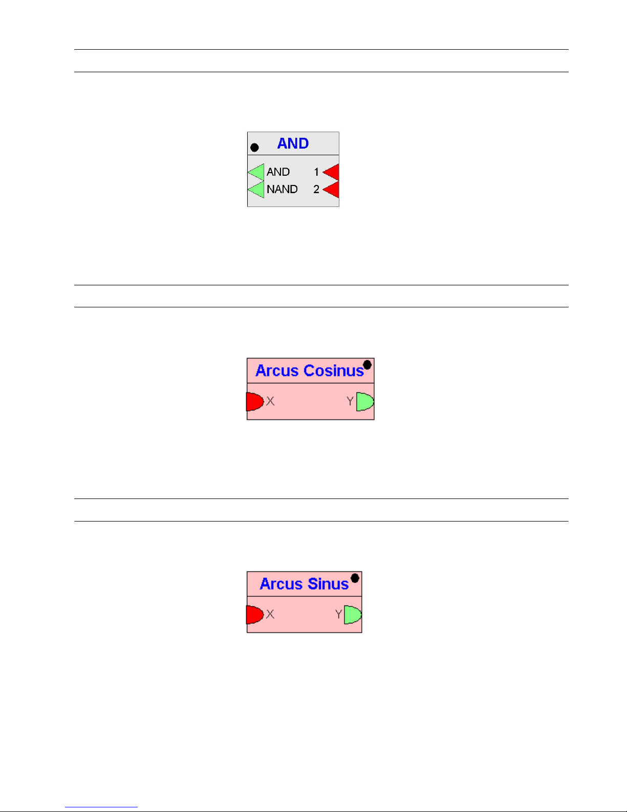
Arcus Cosinus (Excel Web / Excel Web II)
Function Calculates the arcus cosinus function of X. Output value will be returned in radian.
I/O Dialog Box
Input One analog input. Range: –1 to 1. Values out of range will be adopted.
Output One analog output. Range: 0 to
π.
Internal Parameters None.
Arcus Sinus (Excel Web / Excel Web II)
Function Calculates the arcus sinus function of X. Output value will be returned in radian.
I/O Dialog Box
Input One analog input. Range: –1 to 1. Values out of range will be adopted.
Output One analog output. Range: –
π/2 to π/2.
Internal Parameters None.
ALPHABETIC REFERENCE EXCEL CARE CONTROL ICONS
74-5577–33 (US) 26
EN2B-0184 GE51 R0518 (Europe)
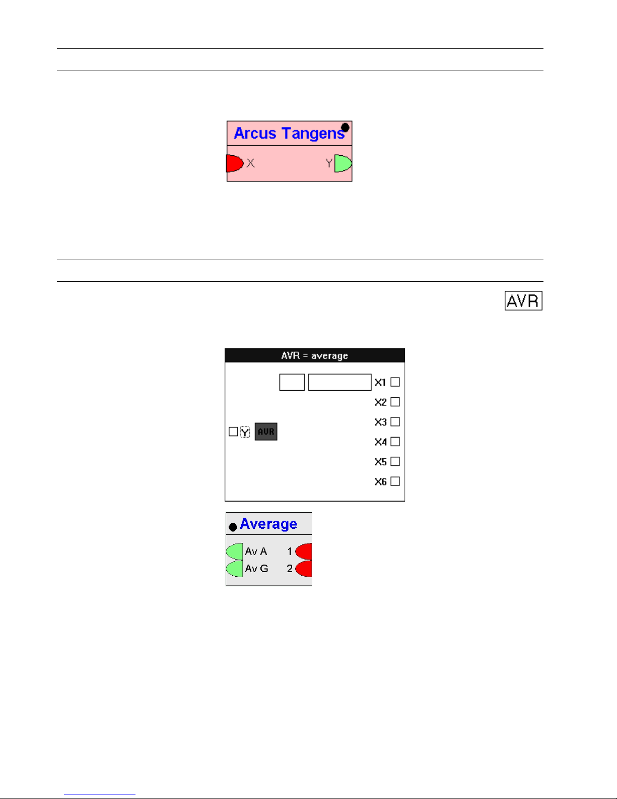
Arcus Tangens (Excel Web / Excel Web II)
Function Calculates the arcus tangens function of X. Output value will be returned in radian.
I/O Dialog Box
Input One analog input. Range: –
∞ to ∞.
Output One analog output. –
π/2 to π/2.
Internal Parameters None.
Average / AVR
Function Calculate the average of multiple analog input s.
I/O Dialog Box
Excel Web / Excel Web II
Inputs Two through six analog inputs (X1 through X6).
You can enter the first input as a parameter (engineering unit index number and
value).
Two through thirty two analog inputs (1 through 32, Excel Web / Excel Web II).
Output One analog output (Y).
Arithmetical (AvA) and geometrical (AvG) average as analog outputs (Excel Web /
Excel Web II).
Internal Parameters None.
EXCEL CARE CONTROL ICONS ALPHABETIC REFERENCE
27 74-5577–33 (US)
EN2B-0184 GE51 R0518 (Europe)
Cascade / CAS
Function Provide both a master Proportional-Integral (PI) controller and a secondary PI
controller to handle difficult control sections. The master PI manages the setpoint for
the secondary (cascade) PI. The secondary PI provides the setpoint reset schedule
which, because of the PI function, can be nonlinear.
CAS operates the same as a PI controller with the addition of a compensation input.
See the Cascade Operation note in this section for more details. Also see the PID
section for more details on PID operation.
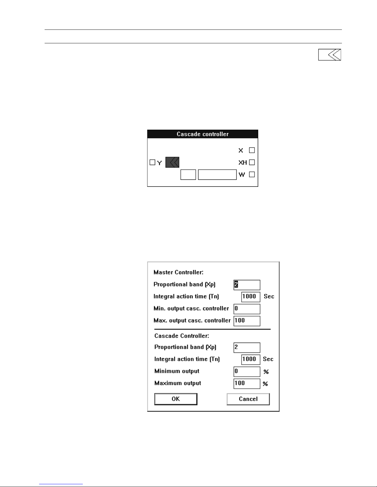
I/O Dialog Box
Inputs Three analog inputs, where:
X = Master-controlled variable.
XH = Cascade- or auxiliary-controlled variable.
W = Reference variable, also known as setpoint.
You can enter the reference variable as a parameter (engineering unit index number
and value).
Output One analog output (Y).
Internal Parameters

ALPHABETIC REFERENCE EXCEL CARE CONTROL ICONS
74-5577–33 (US) 28
EN2B-0184 GE51 R0518 (Europe)
Master controller Proportional band Xp
Number type: decimal, Unit: same as the controlled variable (X)
Default: 2.0, Range: 0 through 100.0
Proportional band value is equivalent to the throttling range.
Integral action time Tn
Number ty pe: whole num ber, Unit: sec ond s
Default 1000 sec, Range: 0 through 7200 sec
If Integral action time is less than 15 seconds, integral control is disabled.
Minimum output
Number type: decimal, Unit: same as the cascade-controlled variable (XH)
Default: 0.0, Range: 0 through 100.0
Maximum output
Number type: decimal, Unit: same as the cascade-controlled variable (XH)
Default: 100.0, Range: 0 through 100.0
Cascade controller Proportional band Xp
Number type: decimal, Unit: same as the cascade-controlled variable (XH)
Default: 2.0, Range: 0 through 100.0
Proportional band value is equivalent to the throttling range.
Integral action time Tn
Number ty pe: whole num ber, Unit: sec ond s
Default: 1000 sec, Range: 0 through 7200 sec
If Integral action time is less than 15 seconds, integral control is disabled.
Minimum output
Number type: decimal, Unit: percent
Default: 0.0 percent, Range: 0 through 100.0 percent
Maximum output
Number ty pe: deci ma l, Unit: percent
Default: 100.0 percent, Range: 0 through 100.0 percent
Parameter Number
Descriptions P3 Xp (proportional band master controlle r)
P4 Tn (in seconds, integral action time of the master controller)
P5* Min (minimum limit of the cascade controller)
P6* Max (maximum limit of the cascade controller)
P7 Xp (proportional band of the cascade control ler)
P8 Tn (in seconds, integral action time of the cascade controller)
P9 Min (minimum limit of the positioning signal, in percent)
P10 Max (maximum limit of the positioning signal, in percent)
P11 W (reference variable if entered as a parameter, not con nect ed to a point)
Not for Excel Web / Excel Web II !
* Parameters P5 and P6 serve as the minimum and maximum limits,
respectively, of the set po int as sign men t to the casca de contr oller.
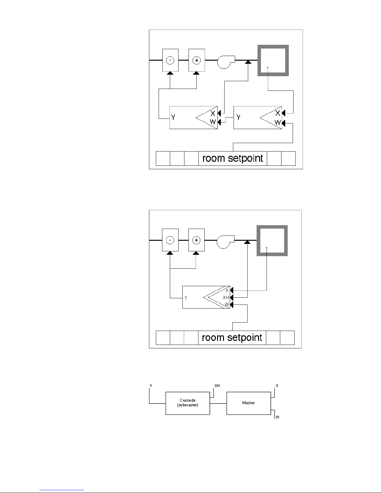
Cascade Operation As an example, the following diagram shows a master PID that is the room
temperature controller and a secondary PID that is the fresh air temperature
controller. The advantage of this arrangement is that the master controller and
secondary controller can each adapt to their own control sections.
EXCEL CARE CONTROL ICONS ALPHABETIC REFERENCE
29 74-5577–33 (US)
EN2B-0184 GE51 R0518 (Europe)
The next diagram illustrates the use of a Cascade controller to perform the same
functions. The CAS controller contains two PI controllers in a “cascade”
arrangement. The X variable reads the master-controlled variable (room
temperature). The XH variable reads the fresh air temperature (auxiliary-controlled
variable). The W variable is the room temperature setpoint (reference variable).
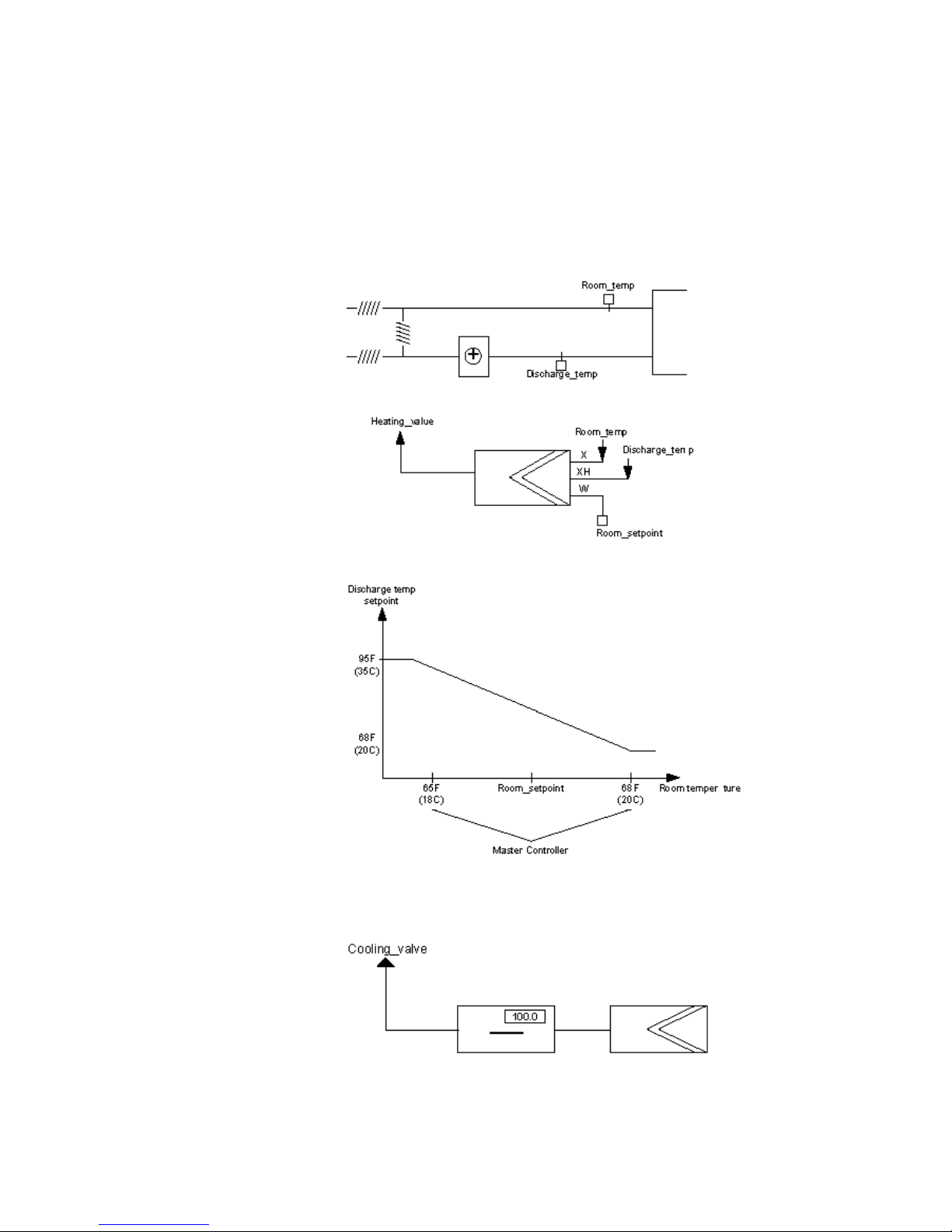
Setpoint Reset Example This example shows how to use cascade control to reset a discharge air controller
setpoint up to 95F (35C) if room temperature falls below its setpoint to 65F (18C).
The submaster controls the controller setpoint. The output of the master controller
resets the setpoint of the submaster up and down.
Parameters for the master controller are:
ALPHABETIC REFERENCE EXCEL CARE CONTROL ICONS
74-5577–33 (US) 30
EN2B-0184 GE51 R0518 (Europe)
Min output = 68F (20C)
Max output = 95F (35C)
W = 65F (18C)
X = ROOM_TEMP
Parameters for the cascade controller are:
Min output = 0 percent
Max output = 100 percent
XH = discharge temperature
Equipment diagram:
Cascade operation:
Direct vs Reverse Acting The output of the CAS operator is reverse acting. To use in a cooling application,
you need a direct-acting output. Use the DIF operator and set the first input to a
value of 100.0. This operation reverses the output.
EXCEL CARE CONTROL ICONS ALPHABETIC REFERENCE
31 74-5577–33 (US)
EN2B-0184 GE51 R0518 (Europe)
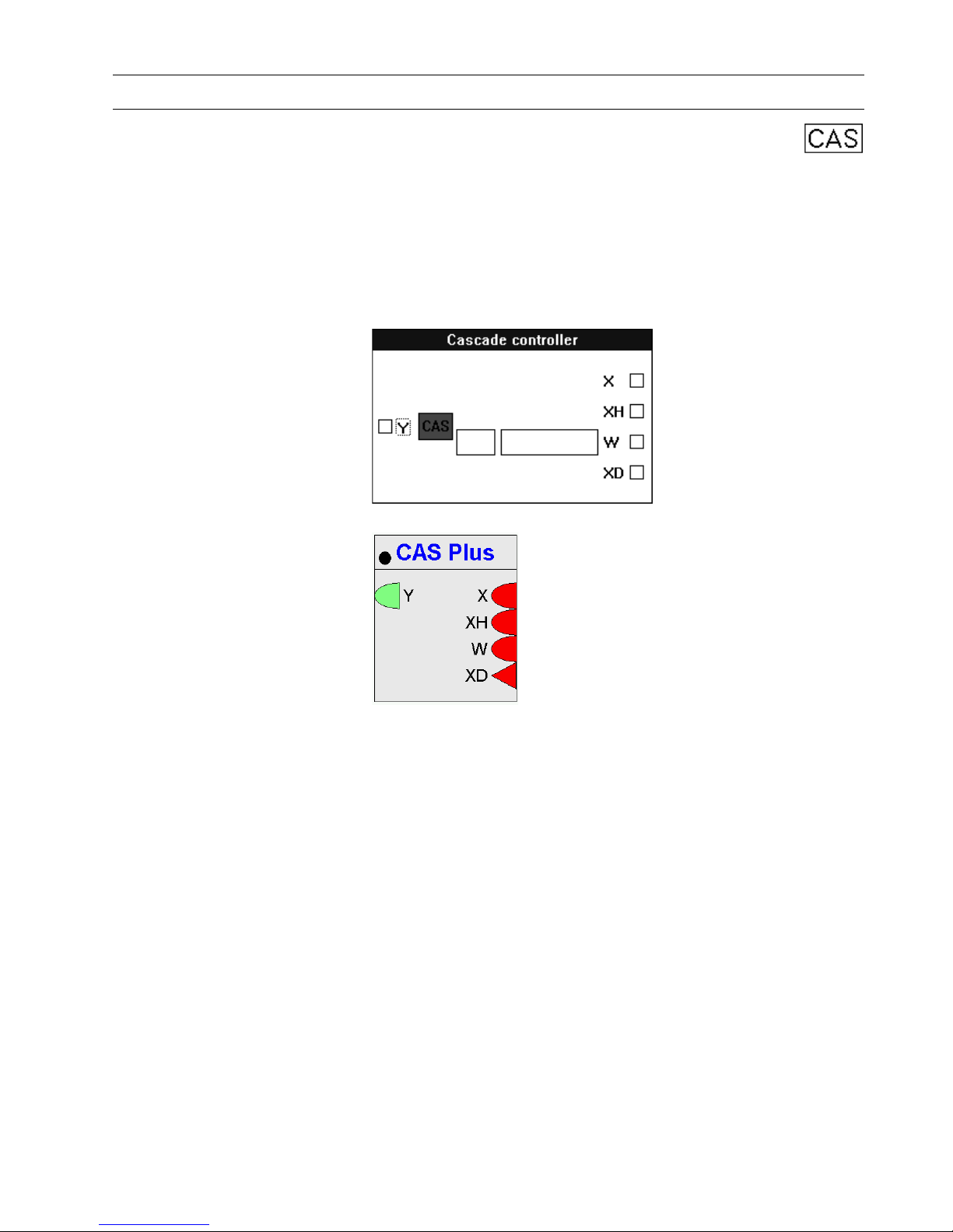
Cascade Plus / CAS
Function Cascade controller that acts as a PI controller with a master and cascade controller.
Cascade Differences This cascade cont roll er (CAS Plus) a ct s ju st like the previous cascade controller
except that it has an integral action enable/disable input. This new function requires
an additional digital input (XD) and two new parameter registers for temporary
storage.
This additional input enables CAS Plus to act as a P controller during plant start-up
and then switch on an Integral component after start-up is complete.
I/O Dialog Box
Excel Web / Excel Web II
Inputs Three analog inputs, where:
X = Master-controlled variable.
XH = Cascade- or auxiliary-controlled variable.
W = Reference variable, also known as setpoint
You can enter the reference variable as a parameter (engineering unit index number
and value). Not for Excel Web / Excel Web II !
One digital input (XD, Excel Web / Excel Web II Icon) that enables and disables
integral control action. When XD is zero, integral action in the master and cascade
controllers is disabled and the associated integral sum is reset. XD/Ion must always
be connected.
Outputs One analog output (Y).

ALPHABETIC REFERENCE EXCEL CARE CONTROL ICONS
74-5577–33 (US) 32
EN2B-0184 GE51 R0518 (Europe)
Internal Parameters
Master controller Proportional band Xp
Number type: decimal, Unit: same as controlled variable (X)
Default: 2.0, Range: 0 through 100.0
Proportional band value is equivalent to the throttling range.
Integral action time Tn
Number ty pe: whole num ber, Unit: sec ond s
Default 1000 sec, Range: 0 through 7200 sec
If Integral action time is less than 15 seconds, integral control is disabled.
Minimum output
Number type: decimal, Unit: same as the cascade-controlled variable (XH)
Default: 0.0, Range: 0 through 100.0
Maximum output
Number type: decimal, Unit: same as the cascade-controlled variable (XH)
Default: 100.0, Range: 0 through 100.0
Cascade controller Proportional band Xp
Number ty pe: decimal, Unit: same as cascade-controlled variable (XH)
Default: 2.0, Range: 0 through 100.0
Proportional band value is equivalent to the throttling range.
Integral action time Tn
Number ty pe: whole num ber, Unit: sec ond s
Default: 1000 sec, Range: 0 t h rough 720 0 sec
If Integral action time is less than 15 seconds, integral control is disabled.
Minimum output
Number type: decimal, Unit: percent
Default: 0.0 percent, Range: 0 through 100.0 percent
Maximum output
Number type: decimal, Unit: percent
Default: 100.0 percent, Range: 0 through 100.0 percent
Parameter Number
Descriptions If W is NOT entered as a parameter:
P3 Xp (proportional band master controlle r)
 Loading...