

Page 1

HONEYWELL EXCEL 5000 OPEN SYSTEM
Excel 100/500/600
CONTROLLERS
SYSTEM OVERVIEW
Copyright © 2008 Honeywell Inc. • All Rights Reserved EN0B-0091GE51 R0708
Page 2
EXCEL 100/500/600 – SYSTEM OVERVIEW
A
XW570
C-BUS
EBI/SymmetrE
LARM PRINTERREPORT PRINTER
Excel 500
XC5010C
Excel 600
Excel 800
Excel 20
LOCAL
LonWorks
NETWORK
DISTRIBUTED
I/Os
EXCEL 800
I/Os
LonWorks
Excel 50
Excel 500
XC5010C
Excel 10 Chilled
Ceiling Controller
3rd-party
LonWorks
products
modem /
ISND adapter
Excel 500
XC5010C
LonWorks
DISTRIBUTED I/Os
modem /
ISND adapter
modem /
ISND adapter
Excel 500
XC5210C
3rd-party
LonWorks
products
Excel 500
XCL5010
EN0B-0091GE51 R0708
DISTRIBUTED
I/Os
LOCAL
LonWorks
NETWORK
DISTRIBUTED I/Os
Excel 500
XCL5010
EXCEL 5000 system
Excel 10 Fan Coil Controller
Excel 500
XCL5010
Page 3

EXCEL 100/500/600 – SYSTEM OVERVIEW
CONTENTS
REVISION OVERVIEW..................................................................................................................................................................ii
THE EXCEL 100/500/600 SYSTEM...............................................................................................................................................1
The User Programs ...................................................................................................2
Excel 100 Modules .................................................................................................... 3
Excel 100 Technical Data..........................................................................................3
The Excel 500–XCL5010...........................................................................................4
The Excel 500/600 Internal Modules (not XCL5010) .................................................4
XC5010C Computer Module................................................................................5
XC5210C Computer Module................................................................................5
XC6010 Computer Module ..................................................................................5
XD505A / 508 Communication Submodules........................................................5
XP502 Power Supply Module ..............................................................................6
XF521A Analog Input Module ..............................................................................6
XF526 Analog Input Module ................................................................................6
XF522A Analog Output Module ...........................................................................7
XF527 Analog Output Module..............................................................................7
XF523A Digital Input Module ............................................................................... 7
XF524A Digital Output Module ............................................................................7
XF529 Digital Output Module............................................................................... 7
XF525A Three-Position Output Module ............................................................... 8
Summary of Internal Modules....................................................................................9
Additional Parts .......................................................................................................10
Distributed I/O Modules...........................................................................................11
Analog Input Module XFL521B ..........................................................................11
Analog Output Module XFL522B .......................................................................12
Digital Input Module XFL523B ...........................................................................12
Digital Output Module XFL524B ........................................................................12
Manual Override Unit XFR522A for XFL522A ...................................................12
Manual Override Unit XFR524A for XFL524A ...................................................13
Summary of Distributed I/O Modules....................................................................... 13
Additional Parts .......................................................................................................14
Excel Smart I/O Modules ...................................................................................14
Time Programs........................................................................................................15
System Texts...........................................................................................................15
Installation and Commissioning...............................................................................15
Excel 500/600 Technical Data.................................................................................16
Remote Communication ............................................................................................................................................................ 18
XI581 / XI582 OPERATOR UNIT .................................................................................................................................................19
XL-Online ....................................................................................................................................................................................21
CARE ENGINEERING SYSTEM..................................................................................................................................................23
Live CARE Monitoring and Simulation Tool ............................................................................................................................25
Trademark Information Echelon, LON, L
LonTalk, LonUsers, LonPoint, Neuron, 3120, 3150, the Echelon logo, the L
logo, and the LonUsers logo are trademarks of Echelon Corporation registered in
the United States and other countries. LonLink, LonResponse, LonSupport, and
LonMaker are trademarks of Echelon Corporation.
i EN0B-0091GE51 R0708
ONMARK, LONWORKS, LonBuilder, NodeBuilder, LonManager,
ONMARK
Page 4

CONTENTS EXCEL 100/500/600 – SYSTEM OVERVIEW
REVISION OVERVIEW
The following pages have been changed from the previous release of this document:
Pages Changes
throughout All references to GSM modem have been eliminated. Occurrences of XBS have been replaced with
EBI/SymmetrE.
EN0B-0091GE51 R0708 ii
Page 5

EXCEL 100/500/600 – SYSTEM OVERVIEW
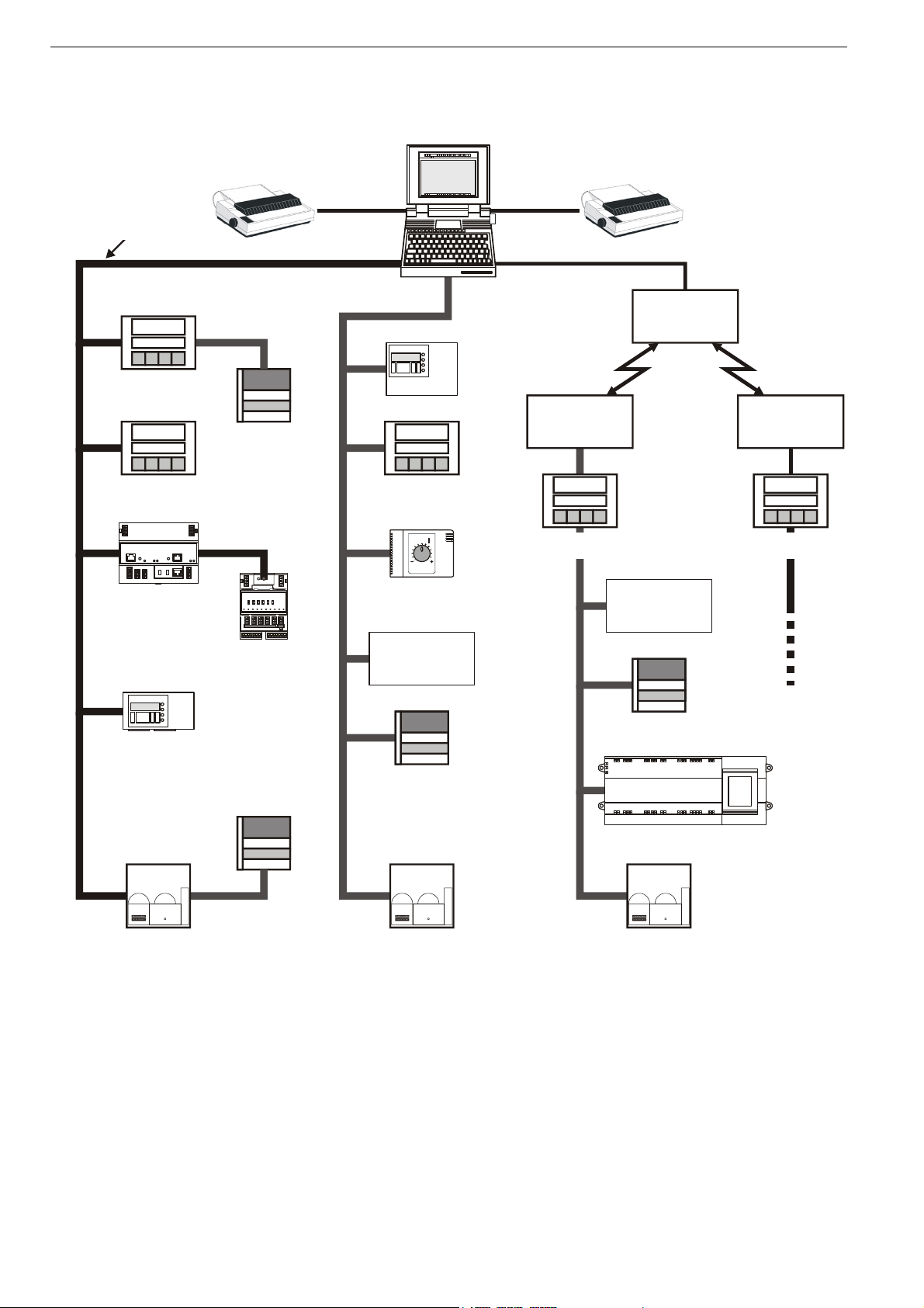
THE EXCEL 100/500/600 SYSTEM
Excel 100/500/600 Excel 100/500/600 is a freely programmable control and monitoring system for
building applications.
In addition to control applications for heating, ventilation and air conditioning, Excel
100/500/600 also performs energy management functions such as optimum
start/stop, night purge, maximum load demand, and many others.
Freely programmable L
controller (Excel 500, only) It supports up to 512 NVs which can be mapped to data points. It can function on a
Connection to building supervisors Up to eight building supervisors can be connected via the Honeywell system bus (C-
Communication via analog/ISDN modem Excel 500 (with firmware version 2.01.00 and higher) and Excel 100C allow direct
Modular design and easy operation The modular design enables the system to be expanded to meet the growing needs
Distributed I/O modules and The modules consist of an electronic module and a terminal module. The terminal
Excel Smart I/O modules connected module provides terminals for all field signals. Internal wiring between the Excel 500
via L
Large remote trend buffer The XC5210C Excel 500 CPU module provides an enlarged remote trend buffer
ONMARK The Excel 500 controller complies with the LONMARK ® Interoperability Guidelines.
L
ONWORKS® network with Excel 10 and Excel 50 controllers, other Excel 500
controllers and their Distributed I/O modules, and third-party L
ONWORKS devices and
centrals. The Excel 500 provides the following unique benefits:
Automatic binding of Excel 500 controllers and Honeywell I/O modules. This
saves engineering time and cost over usual network variable (NV) binding. In
addition, this saves on Echelon® node royalty fees.
512 NVs supported for integration and interoperation with other devices on the
L
ONWORKS network.
NV-Booster® functionality avoids multiple NVs with many-to-one bindings and
thus reduces the number of Excel 500 controllers needed.
All binding information from and to the Excel 500 controller can be saved in
Flash memory or uploaded together with the application and restored after power
failure. This also allows exchange of controller hardware without redoing the
complete binding.
The Excel 500 controller allows conversion of NV types which increases flexibility
and interoperability on a L
ONWORKS network.
With firmware 2.06.00 and higher, Excel 500 controllers support full Building
Management Functionality (BMF) over L
ONWORKS (alarming, scheduling,
trending).
Bus). Excel 100/500/600 allows communication with an EBI/SymmetrE building
supervisor via modem or ISDN terminal adapter.
connection of an analog modem or ISDN terminal adapter, with data transmission
rates of up to 38.4 Kbaud.
of the building. The user addresses and the full English-language descriptors are
stored in the controller and are, therefore, available to be viewed locally, at the
operator unit, without the need for a central PC.
NOTE: The Excel 500-XCL5010 and the Excel 100C have no internal display; thus,
an XI582 or an XL-Online is needed.
ONWORKS
®
bus controller and the field terminals is not required (except for the 2-wire LONWORKS
bus connection). Optional manual override modules and manual disconnect modules
are available.
Excel Smart I/O modules are L
suitable for all L
ONWORKS environments. They feature a variety of software-
ONMARK association-compliant devices, and are thus
configurable digital and analog inputs and outputs and can be installed at strategic
locations throughout buildings.
NOTE: The Excel 500-XCL5010 can be connected only to external I/O modules.
The connection of internal plug-in modules is not possible.
which allows more than 10,000 historical values to be stored and transmitted to a
building supervisor.
1 EN0B-0091GE51 R0708
Page 6

EXCEL 100 SYSTEM EXCEL 100/500/600 – SYSTEM OVERVIEW
The User Programs
Free selection of applications The Excel 100/500/600 receives its user programs in three different ways:
Permanent applications from EPROM With the selection of the applications for the EPROM, the user program is
assembled from permanently programmed functions when starting the system for
the first time – no further programming tools are necessary. With Flash-EPROM,
applications can be stored restored via the operator interface.
Configurable applications With the CARE engineering system, standard applications for heating, ventilation
and air conditioning technology can be assembled and extended as desired.
No programming experience needed With free program preparation using CARE, the user program is generated auto-
matically after graphical preparation of the system schematic diagram, the
instrumentation and control strategies.
EN0B-0091GE51 R0708 2
Page 7

EXCEL 100/500/600 – SYSTEM OVERVIEW EXCEL 100/500/600 SYSTEM
Excel 100 Modules
MCE 3 and MCE 1 The MCE 3 and MCE 1 are analog/digital converters that convert analog outputs of
the Excel 100 into digital outputs. The MCE 1 converts one analog output into one
voltage-free changeover contact. The MCE 3 converts three analog inputs into two
voltage-free outputs and one N.O. contact.
MCD 3 The MCD 3 is an analog/digital converter that converts 1 analog output into one
voltage-free changeover contact and one analog output into a three-point output.
MCM 1 The MCM 1 is a 4-channel separation module that provides active switching
voltages to the digital inputs of the Excel 100 from up to four voltage-free contacts.
Excel 100 Technical Data
Voltage:
24 Vac, ± 20%, 50 to 60 Hz
24 Vdc, + 20%, – 10%
IMPORTANT
If the Excel 100C is supported with, e.g. a battery or accumulator, it has to
be assured that no “pumping” of the power supply occurs.
Maximum number of devices per System Bus:
30
Power consumption:
max. 40 VA (max. 30 W)
Ambient temperature:
During operation: 0 to 50°C (0 to 45°C when mounted horizontally)
During storage: -20 to 60°C
Ambient humidity:
During operation and storage 5 to 90% r.h.
Dimensions of housing:
235 x 192 x 72 mm (H x W x D)
Mounting:
Wall or DIN rail mounting
Program back-up during power failure:
72 hours via gold capacitor
Protection class:
IP 30 (with cover mounted)
Operator units:
Operator unit XI582 desktop or wall mounting
XL-Online
Table 1. Excel 100 Modules
module type hardware
Analog/digital converter MCD 1 1 analog input for one voltage-free changeover contact
Analog/digital converter MCD 3
Analog/digital converter MCE 3
Separation module MCM 1 4 voltage-free contacts for 4 digital inputs
1 analog input for one voltage-free changeover contact
1 analog input for one three-point output
2 analog inputs for two voltage-free changeover
contacts; 1 analog input for one voltage-free N.O.
contact
3 EN0B-0091GE51 R0708
Page 8
EXCEL 100/500/600 SYSTEM EXCEL 100/500/600 – SYSTEM OVERVIEW
(
)
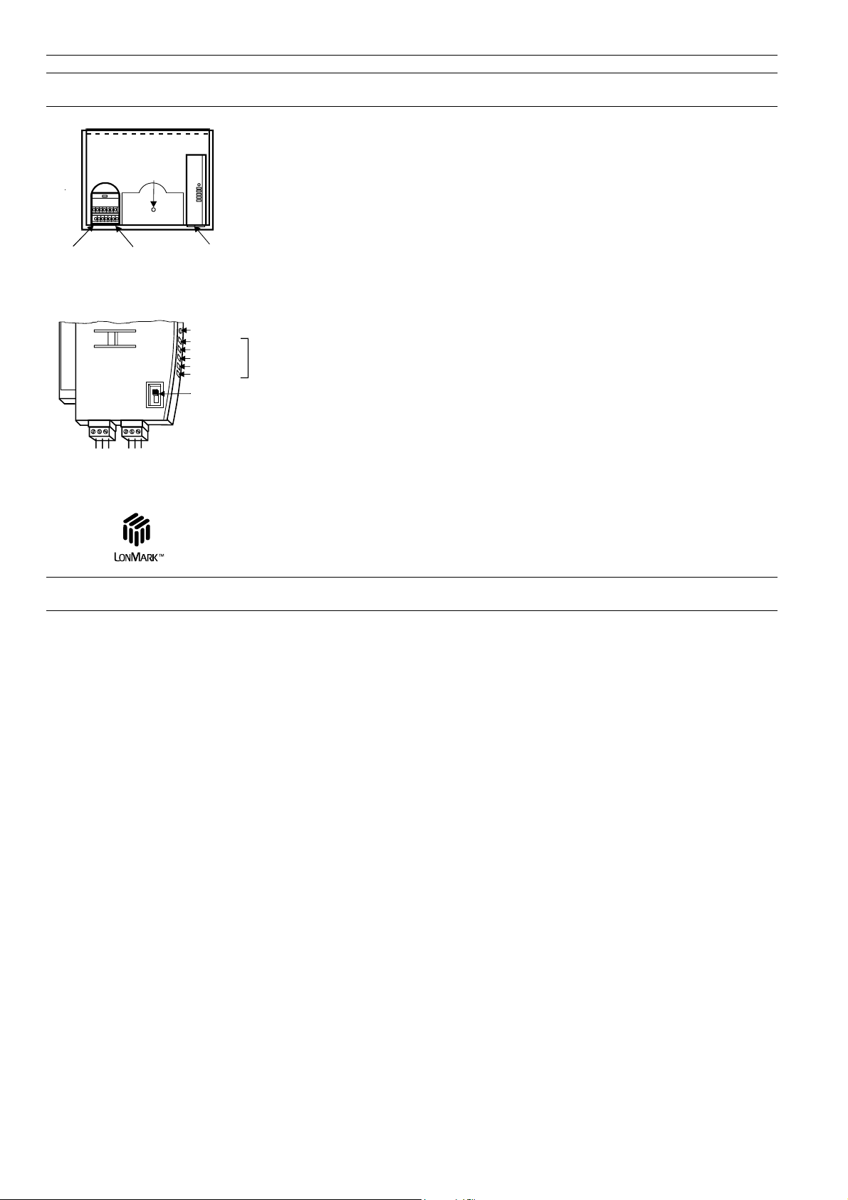
The Excel 500–XCL5010
Excel 500
SCREW
TERMINAL
BLOCK
REMOVABLE
(XCL5010)
RESET
BUTTON
REMOVABLE FUSE
BELOW
TERMINAL BLOCK
COMMUNICATION
MODULE
(REMOVABLE)
XCL5010 Controller
LON SERVICE BUTTON
POWER, GRN
LON SERVICE, RED
C-BUS TxD, YEL
C-BUS RxD, YEL
RESERVED
C-BUS
TERMINATION
SWITCH
45
LON
BUS
12
6
3
A1
A2
C-BUS
C -
C +
SHIELD
NOT USED
Communication Module XDL505
The Excel 500–XCL5010 controller is specially designed for operation with Distributed
Ter m_ Bl k
I/O modules or Smart I/O modules via a L
functions are performed by means of programmable, 16-bit microprocessor controlled,
ONWORKS bus. Control and monitoring
digital technology. The Excel 500 System is freely programmable and can be used as
a stand-alone controller or as part of a network of up to 30 controllers connected via a
C-bus (9.6 Kbaud up to 76.8 Kbaud) or as part of an open L
ONWORKS network.
The Excel 500 System provides energy management and control functions in
Honeywell C-Bus networks or in L
ONWORKS networks. In the case of a Honeywell C-
Bus network, up to 16 Distributed I/O modules with up to 128 inputs and outputs can
be connected. A maximum of 10 modules of the same type is allowed per system. In
the case of a L
ONWORKS network, the maximum number of Distributed I/O modules is
determined by the number of NVs needed for interoperation. In a typical case, 190
physical inputs and outputs can be controlled per Excel 500.
Applications for the Excel 500 can be programmed during CARE engineering and then
LEDs
downloaded in the Flash EPROM.
Memory is buffered by a gold capacitor and will be supported for approximately 72
hours in case of a power failure.
The XCL5010 controller comprises an internal power supply and allows the connection
of CPU and I/O modules to the same transformer (shared transformer).
00000124
An external MMI, modem, or ISDN adapter can be connected to the controller’s serial
port.
The Communication Module provides ports for C-bus and L
ONWORKS bus connection,
as well as LEDs for indicating the controller's operational status, transmit status, and
receive status.
The Excel 500/600 Internal Modules (not XCL5010)
The Excel 500/600 system with internal modules is comprised of the XC5010C
(Excel 500) or XC6010 (Excel 600) computer modules for freely programmable
applications, the power supply module XP501 or XP502 with an external transformer
as well as a range of input and output modules.
Clear functional allocation The internal input and output modules are:
Analog input modules XF521A / XF526
Analog output modules XF522A / XF527
Digital input modules XF523A / XF528
Digital output modules XF524A / XF529
Three-position output module XF525A
One important functional characteristic of the output modules XF522A, XF524A and
XF525A is the integral manual override facility to switch equipment and position
actuators directly from the module. The output modules XF527 and XF529 are
equipment variants without manual override switches. The status of the inputs and
outputs is shown by LEDs.
An Excel 500/600 can consist of 16 input and output modules providing a total of
128 points. The system can be expanded by connecting additional controllers if the
number of inputs and outputs is insufficient for a particular application. Communication is performed via the system bus.
In general, the maximum system bus length is 1200 meters. However, a bus
repeater (XD509) is available to exceed this limit.
EN0B-0091GE51 R0708 4
Page 9
EXCEL 100/500/600 – SYSTEM OVERVIEW EXCEL 100/500/600 SYSTEM
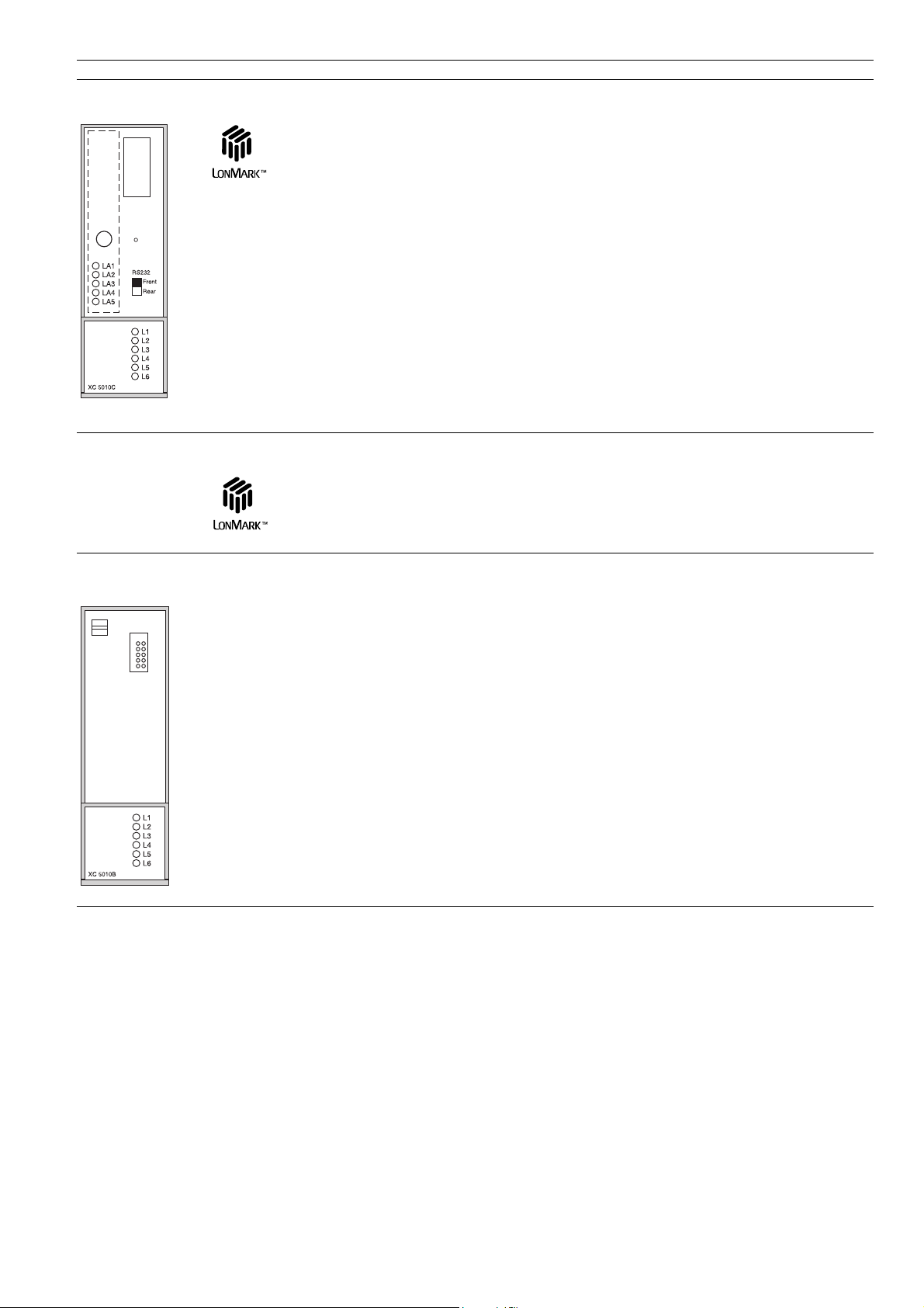
XC5010C Computer Module
The XC5010C computer module is the brain of Excel 500 and features internal
modules. Control and monitoring functions are performed by means of programmable, 16-bit microprocessor controlled, digital technology. The program is held
in RAM, but it can also be saved onto a Flash-EPROM. RAM is buffered by a gold
capacitor and is supported for approx. 72 hours in case of a power failure.
The XC5010C adds support for a L
modules and to other controllers and L
cation support for MMI is possible via two interfaces, Sub-D (front) and 18-pin male
(back), which can be selected using a switch on the front panel. The interface enables
the system to be expanded to up to 30 devices including a building supervisor.
Communication is performed via the system bus using a token-passing multi-master
structure. LEDs indicate the operational status as well as the transmit / receive status
of the interfaces.
ONWORKS network connection to Distributed I/O
ONMARK devices. Serial interface communi-
XC5210C Computer Module
The XC5210C computer module has all the same functions and capabilities as the
XC5010C described above with one exception. Increased memory allows for a
greatly increased remote trend buffer capacity – up to 10,000 values can be stored.
XC6010 Computer Module
The XC6010 computer module is the 32-bit, high performance version of the
XC5010C computer module. It features more memory and faster DCC cycle-times as
well as faster scanning times in combination with some of the input / output modules.
The XC6010 computer module has only a single serial interface connection and does
not support L
used with the XC6010C.
ONWORKS bus connections; therefore, Distributed I/O modules cannot be
XD505A / 508 Communication Submodules
The submodules XD505A and XD508 are used for C-bus communication with older
Excel 100/500 and Excel 600 controllers. The submodules are plugged onto the
Excel 100B or XC5010B/XC6010 computer modules.
5 EN0B-0091GE51 R0708
Page 10

EXCEL 100/500/600 SYSTEM EXCEL 100/500/600 – SYSTEM OVERVIEW
XP502 Power Supply Module
The XP502 power supply module supplies the low voltage power to the internal
modules via the internal bus.
• The on/off switch for the power supply is situated on the front panel of the
XP502 power supply module.
• The module can be connected with an external uninterrupted power supply
(UPS), XAPU 24-2F.
• LEDs indicate the operating status, status of the watchdog relay and operation
by battery.
XF521A Analog Input Module
The XF521A analog input module has eight inputs. It converts data from analog
sensors PT 1000, NTC 20K, 0 to 10V and (0…20 mA, 4…20 mA). The resolution
is 12 bit. The characteristic curves for the different sensor types are entered in the
data point description.
XF526 Analog Input Module
The XF526 analog input module has eight inputs. It converts data from additional
analog sensors: PT 100, PT 1000, PT 3000, BALCO 500, NTC 20K, 0 to 10V and
(0…20 mA, 4…20 mA). The characteristic curves for the different sensor types are
entered in the data point description.
The single LED indicates that the internal processor is working.
EN0B-0091GE51 R0708 6
Page 11

EXCEL 100/500/600 – SYSTEM OVERVIEW EXCEL 100/500/600 SYSTEM
XF522A Analog Output Module
The XF522A analog output module has eight outputs that supply a 0…10V signal.
The resolution is 8 bit.
Five of the outputs are equipped with a manual override switch that can be used to
select 0V, 10V or automatic operation.
The module can be adapted to suit a variety of actuators by entering the
characteristic curves in the data point description.
The intensity of the LEDs is proportional to the output voltage.
XF527 Analog Output Module
This module has the same functionality as XF522A, but without manual override
switches. The analog outputs are controlled by software, only.
XF523A Digital Input Module
The XF523A digital input module has twelve inputs. It processes floating signals as
well as non-floating signals up to 24 V AC/DC. The inputs can also be used as
totalizer inputs.
The following specifications apply to totalizer inputs:
• Inputs 1 and 2:
Maximum frequency 15 Hz
Minimum pulse duration 20 msec
Minimum pulse interval 33 msec
• Inputs 3 to 12:
Maximum frequency 0.4 Hz
Minimum pulse duration 1.25 sec
Minimum pulse interval 1.25 sec
• LEDs indicate the respective status of the inputs. The LEDs are invertible
(NO/NC).
XF524A Digital Output Module
The XF524A output module has six relay outputs, including five with changeover
contacts and one with a normally open contact.
The five changeover contacts can be activated and deactivated independent of the
user program by a manual switch. This is particularly useful for commissioning and
servicing. The relays are integrated in the XF524A module and eliminate the need
for externally mounted interlocking relays and their associated additional wiring.
LEDs indicate the status of all six outputs.
XF529 Digital Output Module
This module has the same functionality as XF524A, but without manual override
switches. The digital outputs are controlled by software, only.
7 EN0B-0091GE51 R0708
Page 12

EXCEL 100/500/600 SYSTEM EXCEL 100/500/600 – SYSTEM OVERVIEW
XF525A Three-Position Output Module
The XF525A three-position output module was specifically developed for controlling
reversible actuators.
A total of three actuators can be connected directly to the XF525A three-position
output module. Both 24 Vac and 240 Vac actuators can be operated. The module
features radio interference suppression for actuators with a current draw of up to
0.2 A (240 Vac) or 1.2 A (24 Vac). The control relays are already incorporated in
the three-position output module and eliminate the need for externally mounted
interlocking relays and their associated additional wiring.
Actuators with different running times can be connected directly to this output
module. The OPEN and CLOSE running times can be individually entered in the
data point description for each actuator connected.
The three outputs can be independently set to + | 0 | - | AUTO by means of the
manual override switch.
LEDs indicate if a signal is present at the output.
EN0B-0091GE51 R0708 8
Page 13

EXCEL 100/500/600 – SYSTEM OVERVIEW EXCEL 100/500/600 SYSTEM
Summary of Internal Modules
Table 2. Excel 500/600 internal modules
module name inputs outputs
XC5010C
(16-bit)
Computer module
XC5210C
(16-bit, large
trend buffer)
XC6010
(32-bit)
Power supply module XP502
Analog input module
Analog output module
Digital input module XF523A 12
Digital output module
Three-position output
module
C-bus repeater XD509
* RS232 connection on front or rear of XC5010C (switchable), only on rear of XC6010.
For XC6010, only, there are submodules for system bus combination, XD505A (10 KBit) / 508 (1 MBit).
XF521A 8
XF526 8
XF522A 8
XF527 8 8 x Output intensity
XF524A
XF529 5 changeover 6 x Status
1 N.O. contact
XF525A 3 three-position
* *
* *
* *
5 changeover
1 N.O. contact
manual override
switches
(1 x) 0
1
(5 x) 0
1
Auto
(5 x) 0
1
Auto
(3 x) +
0
Auto
LED display
Normal
System error
Transmit
Receive
Ground loop
L
ONWORKS service
C-bus receive
C-bus transmit
Normal
System error
Transmit
Receive
Ground loop
L
ONWORKS service
C-bus receive
C-bus transmit
System bus transmit
System bus receive
Power supply
Watch dog
Battery
8 x Output intensity
12 x Status
LEDs inevitable
6 x Status
3 x Open close
9 EN0B-0091GE51 R0708
Page 14

EXCEL 100/500/600 SYSTEM EXCEL 100/500/600 – SYSTEM OVERVIEW
Additional Parts
Excel 500/600 Socket / Housing (not XCL5010):
Socket for wall mounting...................................XS563
Socket for front door mounting..........................XS564
Housing (empty, without socket) .......................XH561
Blank cover .......................................................XH562
Operating unit, controller cover .........................XIS581
Excel 500/600 Cable for housing connection:
CAUTION
Incorrectly inserted cables can destroy the modules installed.
Use the cables only as described.
Cable 80 mm (not XCL5010) ...........................XW568
Only for horizontal housing connection (housing along side one another).
Cable 330 mm (not XCL5010) .........................XW569
Only for vertical housing connection (housings one above the other).
Cable for connection from controller to XI582:
Cable to XI582 (2.5 m) (XC6010)......................XW564
Cable to XI582 (5 m) (not XCL5010).................XW565
Cable to XI582 (15 m) (not XCL5010)...............XW566
Cable to XI582AH (5 m)
(front Excel 100C, XC5010C/XC5210C/
XCL5010)..........................................................XW582
Cable to XI582AH (5 m)
(back Excel 100C, XC5010C/XC5210C)...........XW583
Adapter cable (for connection of
Excel 100B, XC5010B/XC6010) .......................XW584
Cable for connection from computer module to PC / XL-Online:
Cable to XL-Online (2.5 m) (XC6010) ...............XW567
Cable to XL-Online (5 m)
(Excel 100C, XC5010C/XC5210C/XCL5010)....XW585
EN0B-0091GE51 R0708 10
Page 15
EXCEL 100/500/600 – SYSTEM OVERVIEW EXCEL 100/500/600 SYSTEM
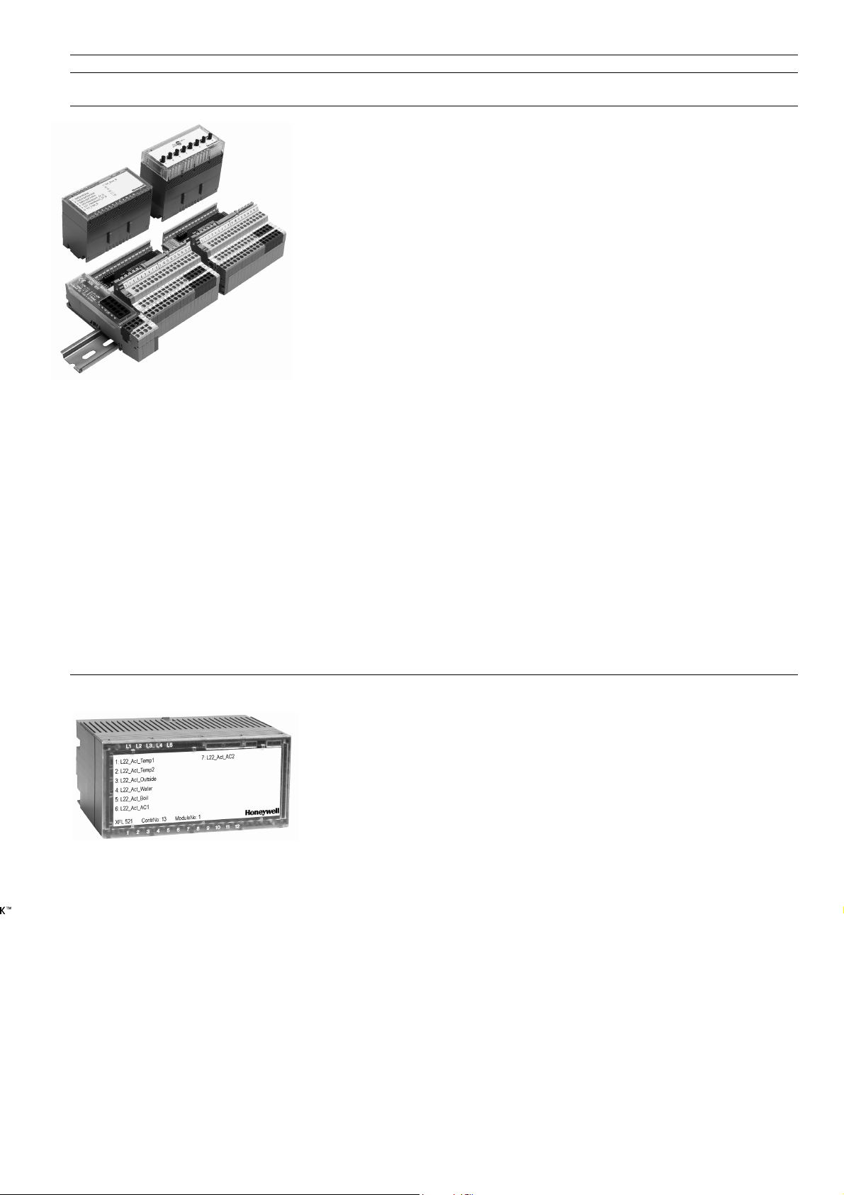
Distributed I/O Modules
Distributed I/O modules are LONMARK -approved and can therefore be used in a
L
ONWORKS network independently of an Excel 500 controller. See Distributed I/O
Modules Product Data (EN0B-0090GE51) for more information.
Distributed I/O modules can be operated with Excel 500 controllers in C-Bus networks
or in L
ONWORKS networks.
In C-Bus networks, it is possible to control up to a maximum of 16 I/O Distributed I/O
modules. For the XC5010C, this means 16 total modules are supported, including both
internal and distributed. The XCL5010 supports only Distributed I/O modules.
In L
ONWORKS networks, the maximum number of Distributed I/O modules to be used by
a controller is determined by the number of NVs to be used for communication and
interoperation. In a typical case, 190 physical inputs and outputs can be controlled per
Excel 500.
The XFL521, 522, 523, and 524 modules are digital and analog I/O modules that can
be installed at strategic locations within a building. As part of the EXCEL 5000 system,
these modules convert sensor readings and provide output signals used for operating
actuators.
The input and output modules are:
Analog input module XFL521B
Analog output module XFL522B
Digital input module XFL523B
Digital output module XFL524B
Each I/O module plugs into a base terminal block allowing communication with the CPU
via the built-in L
Distributed I/O modules is connected to the L
module. The modular system allows I/O modules to be removed from the system
without disturbing the other modules.
A power LED (L1) and a service LED (L2) are located on each module. L2 indicates the
current state of the bus node. ON indicates that the node has no application loaded,
BLINKING indicates that the node has an application but has not yet been configured,
and OFF indicates loaded application and configured.
ONWORKS bus and easy wiring to the devices. Each set of up to 10
ONWORKS bus via the XSL511 connector
Analog Input Module XFL521B
The XFL521B analog input module has eight input channels that can be used for
connecting sensors or any device that provides an analog output (e.g. PT 1000,
NTC 20K, 0…10 Vdc, 0…20 mA, 4…20 mA). The input values are read by the CPU
and can then be used for monitoring or as parameters that can be used for
controlling other devices. The resolution is 12 bit.
11 EN0B-0091GE51 R0708
Page 16

EXCEL 100/500/600 SYSTEM EXCEL 100/500/600 – SYSTEM OVERVIEW
Analog Output Module XFL522B
The XFL522B analog output module has eight output channels that supply a
0…10 V signal. The resolution is 8 bit. The outputs can be used to control actuators
or other suitable analog devices.
Digital Input Module XFL523B
The XFL523B digital input module has twelve input channels that can be used for
connecting sensors or any device that provides a digital input. The input values are
read by the CPU and can then be used for monitoring or as parameters that can be
used for controlling other devices.
LEDs indicate the respective status of the inputs. Two different LED color sets for
indicating the on/off states can be selected via a DIP switch (sw1: LEDs DI1 to D6;
sw2: LEDs DI 7 to DI 12). The possible on/off colors are: yellow/none or red/green.
Digital Output Module XFL524B
The XFL524B digital output module has six isolated changeover contacts that can
be connected to actuators or other switchable devices. LEDs indicate the status of
all six outputs.
Manual Override Unit XFR522A for XFL522A
The XFR522A manual override module mounts directly on top of the XFL522A.
Eight potentiometers on top of the module can be used to independently vary the
output of each channel from 0% to 100%. Each potentiometer also has an
automatic setting that causes the channel to operate normally. The LEDs of the
XFL522A are also visible.
The manual override unit works independently from the CPU. A feedback signal
that includes the user address, the operating mode (manual/auto), and its value is
sent to the CPU if any changes are made using the manual override unit.
EN0B-0091GE51 R0708 12
Page 17

EXCEL 100/500/600 – SYSTEM OVERVIEW EXCEL 100/500/600 SYSTEM
Manual Override Unit XFR524A for XFL524A
The XFR524A manual override module mounts directly on top of the XFL524A. Six
switches on top of the module can be used to independently switch each of the
digital outputs OFF (0) or ON (1). Each switch also has an automatic setting that
causes the channel to operate normally. The LEDs of the XFL524A are also visible.
The manual override unit works independently from the CPU. A feedback signal
that includes the user address, the operating mode (manual/auto), and its value is
sent to the CPU if any changes are made using the manual override unit.
Summary of Distributed I/O Modules
Table 3. Excel 500 Distributed I/O modules
module name inputs outputs
Analog input module XFL521B 8
Analog output module
Digital input module XFL523B 12
Digital output module
XFL522B 8 8 x output intensity
with XFR522A 8 (8 x) potentiometers 8 x output intensity
XFL524B 6 changeover 6 x status LEDs
with XFR524A 6 changeover
manual override
with feedback
(6 x) 1
0
Auto
LED display
12 x status LEDs
(selectable colors)
6 x status LEDs
13 EN0B-0091GE51 R0708
Page 18

EXCEL 100/500/600 SYSTEM EXCEL 100/500/600 – SYSTEM OVERVIEW
Additional Parts
Socket / Housing:
Terminal block for XFL521/522A/523............. XSL513
Terminal block for XFL524A...........................XSL514
Additional modules:
L
ONWORKS connector module ........................XSL511
Manual disconnect module ............................XSL512
Accessories:
Cover release tool..........................................XAL2
Swivel label....................................................XAL1
Termination module .......................................209541B
Mounting clamps (for XSL512–514)
Excel Smart I/O Modules
Excel Smart I/O modules are LONMARK association-compliant devices, and can thus
be used in all open L
configurable digital and analog inputs and outputs and are suitable for installation at
strategic locations throughout your buildings. The modules convert physical input
signals from sensors into network variables and the network variables into physical
output signals for operating actuators.
The diverse mix of inputs and outputs (flexibly configurable using Honeywell's
LonMaker for Windows™ plug-in) makes the Excel Smart I/O ideally suited for a
wide range of intelligent, distributed applications.
ONWORKS environments. They feature a variety of software-
EN0B-0091GE51 R0708 14
Page 19

EXCEL 100/500/600 – SYSTEM OVERVIEW EXCEL 100/500/600 SYSTEM
Time Programs
Simple and flexible time programs The daily programs must first be defined before a time program can be created. A
daily program is assigned to each weekday in the weekly program. This weekly
program is automatically copied for every week in the annual program. Exceptions
can be defined for any number of days by replacing the daily program directly in the
annual program.
Automatic summer/winter changeover The beginning and end of daylight savings time can be stored to automate the
changeover from daylight savings time to standard time. The changeover is then
performed automatically on the appropriate days.
System Texts
Flexible text files The text files are stored in the controller.
Installation and Commissioning
Freely programmable When the application program for a freely programmable application is generated
application programs during CARE engineering, the complete documentation for the system and the
wiring diagram are generated automatically.
Protection against program loss The application program can be either loaded into the RAM of the computer module
from disk or stored in the computer module’s Flash-EPROM.
User friendly service level The various operating levels can be accessed by means of passwords.
In operator level 3, "read and make changes", all inputs and outputs can be queried,
set, or simulated. The current status of each input and output can be queried. All
relay outputs can be activated or deactivated. Analog outputs can be set to a value
between 0 and 100%. In order to simulate operating conditions, each digital input
can be commanded ON or OFF and each analog input can be assigned a value
between 0 and 100%.
This service level is useful for both commissioning and servicing.
Menu driven programming level Operator level 4 of the XL-Online is primarily used to set the system parameters.
Additionally, the system text and the time program can also be edited.
Excel 500/600 with internal modules (XC5010C/XC6010) Excel 500–XCL5010 with Communication Module
15 EN0B-0091GE51 R0708
Page 20

EXCEL 100/500/600 SYSTEM EXCEL 100/500/600 – SYSTEM OVERVIEW
Excel 500/600 Technical Data
Voltage:
XC5010C/
XC6010: 24 Vac/dc, ± 20%
XCL5010: 24 Vac, ± 20%
Maximum number of modules per Excel 500/600:
16 I/O modules (internal + Distributed; XCL5010 Distributed, only) with up to 128
inputs and outputs.
Up to ten per module type.
Up to ten XF524A digital output modules and XF525A three-position output
modules combined (not XCL5010).
Maximum number of devices per System Bus:
30
Power consumption:
XC5010C/XC5210C/
XC6010: max. 40 VA (max. 30W)
XCL5010: max. 5 VA (max. 4W)
Ambient temperature:
During operation: 0 to 45 °C
During storage: -20 to 70 °C
Ambient humidity:
During operation and storage 5 to 90% r.h. (non-condensing)
Dimensions of housing:
XC5010C/XC6010: 144 x 192 x 188 mm (H x W x D)
XCL5010: 150 x 198 x 97 mm (H x W x D)
Mounting:
Front door (not XCL5010) or panel mounting on DIN-rail
Program back-up during power failure:
72 hours for RAM (XC5010C/XCL5010)
1 month for RAM (XC6010)
Protection class:
IP 30
Operator units:
Operator unit XI581 on unit housing (not XCL5010)
Operator unit XI582 desktop or wall mounting
XL-Online
EN0B-0091GE51 R0708 16
Page 21

EXCEL 100/500/600 – SYSTEM OVERVIEW EXCEL 100/500/600 SYSTEM
Table 4. Excel 500/600 controllers and internal modules
module type hardware software
XC5010C/XC52010C,
Computer module
XCL5010
XC6010 32 bit
Power supply module XP502
Analog input module XF521A / XF526 8 analog inputs
Analog output module XF522A / XF527 8 analog 0...10 V outputs polling every 2 sec.
Digital input module XF523A 12 digital inputs
Digital output module XF524A / XF529
Three pos. output. module XF525A 3 three-position outputs polling every 0.5 sec.
Table 5. Excel 500 Distributed I/O modules
module type hardware software
Analog input module XFL521B 8 analog inputs polling every sec.
Analog output module XFL522B 8 analog outputs updating every sec.
Digital input module XFL523B 12 digital inputs polling every sec.
Digital output module XFL524B 6 changeover contacts updating every sec.
Table 6. Excel Smart I/O modules
type power overrides universal inputs digital inputs analog inputs relays
XFC2A05001 230 Vac no 2 4 2 4
XFC2A06001 230 Vac no 4 4 2 4
XFC3A04001 24 Vac no 4 4 2 4
XFC3A05001 24 Vac no 2 4 2 4
XFC3A06001 24 Vac no 4 4 2 4
XFC2D05001 230 Vac yes 2 4 2 4
XFC2D06001 230 Vac yes 4 4 2 4
XFC3D04001 24 Vac yes 4 4 2 4
XFC3D05001 24 Vac yes 2 4 2 4
XFC3D06001 24 Vac yes 4 4 2 4
16 bit (internal + distributed)
16 bit (distributed, only)
5 changeover contacts
1 normally open contact
Freely programmable
L
ONWORKS network interface
Freely programmable
No L
ONWORKS network interface
polling every sec.
(240 ms with XC6010 fast mode)
polling every sec.
(125 ms with XC6010)
polling every 2 sec.
17 EN0B-0091GE51 R0708
Page 22

EXCEL 100/500/600 – SYSTEM OVERVIEW
REMOTE COMMUNICATION
There are several possibilities for communication of alarms, trending information,
and system data points to a remote building supervisor via modem.
Excel 100C / Excel 500 Excel 500 controllers with firmware version 2.1.x and higher and Excel 100C
controllers can have a modem or ISDN terminal adapter connected directly to their
serial port. This allows communication with an EBI/SymmetrE building supervisor at
data transmission rates of up to 38.4 Kbaud.
The Excel 100C or Excel 500 controller connected to the modem/ISDN terminal
adapter may function as a normal building controller, but it has a buffer that can
store up to 100 trend samples.
EBI / SymmetrE
modem /
ISND adapter
C-BUS
Excel 500
XCL5010
Distributed I/O
(mandatory)
Excel 500
XC5010C
Distributed I/O
(optional)
modem /
ISND adapter
Excel 500
Excel 100 Excel 600
18
EN0B-0091GE51 R0708
Page 23

EXCEL 100/500/600 – SYSTEM OVERVIEW
XI581 / XI582 OPERATOR UNIT
Easy handling on site The XI581 (XC5010C/XC6010, only) or XI582 is the command and information
center of the Excel 100/500/600. Data, such as setpoint values and time switching
programs, can be entered via the operator unit. Important information such as actual
temperature values, control status, etc. can also be displayed.
Buswide access Buswide access allows communication between an XI581 or XI582 and an Excel
Controller that is not directly connected to this operator unit. Communication can
include reading from and writing to the remote controller as well as receiving alarm
status information.
Clear display A menu-driven graphic display with six lines, 34 characters per line and eight clearly
marked keys make the device easy to use. The entire operation uses plain language
text stored in the controller, which can be freely accessed by the user. In addition,
the display features a backlight.
Security due to password The device can be operated at three levels, thereby protecting the data from
controlled operating levels unauthorized access.
Level 1: Read only without password
Level 2: Read plus limited changes with a password
Level 3: Read and make changes with a password
Operator units can be XI581 is mounted directly on the unit housing (XC5010C/XC6010, only).
positioned anywhere
XI582 is the desktop model and is also suitable for wall mounting.
Both devices are connected to the operating interface on the computer module. The
wall and desktop units can be positioned up to 15 meters from the computer module.
XI581 Controller-mounted operator terminal
XI582 Desktop operator terminal
19
EN0B-0091GE51 R0708
Page 24

XI581 / XI582 OPERATOR UNIT EXCEL 100/500/600
EN0B-0091GE51 R0708 20
Page 25

EXCEL 100/500/600
XL-ONLINE
User friendly operation The XL-Online is the local intelligent operating and service device. It performs all the
operating functions of the XI581/XI582 as well as having all the advantages of a PC.
In addition to being able to make major modifications, such as changing setpoint
values and time program switching points, the XL-Online also offers all the service
and commissioning functions.
Password protected operating The Excel Online can be operated at five levels, 3 of which are protected against
levels for: unauthorized access
- User functions
- Service functions Level 1: Read only
- Programming functions Level 2: Change data (e.g. time program)
Level 3: Change data (e.g. data point description)
Level 4: Change parameters
Level 5: Definition of new operators
A printer can be connected to the XL-Online's parallel interface to log alarms and
messages.
Like the XI582, the XL-Online can also be placed up to 15 meters from the computer
module.
Excel 500/600 with XL-Online operator and service computer and printer
XI584con
Excel 500–XCL5010 with XL-Online operator and service computer and printer
21 EN0B-0091GE51 R0708
Page 26

XL-ONLINE OPERATOR AND SERVICE COMPUTER EXCEL 100/500/600
EN0B-0091GE51 R0708 22
Page 27
EXCEL 100/500/600
CARE ENGINEERING SYSTEM
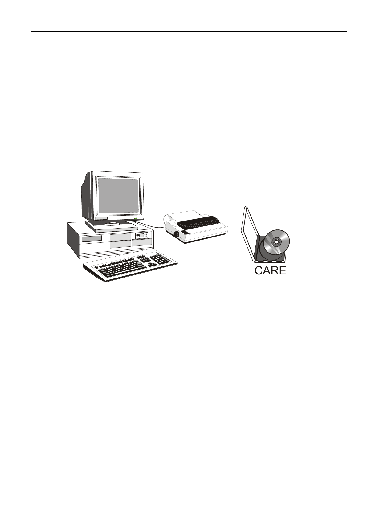
Hardware requirements The CARE engineering system is a software package that can be installed on a
personal computer.
The PC must satisfy the following requirements:
- Pentium 90 MHz CPU (166 MHz recommended)
- 1 free serial interface
- VGA graphics card (800 x 600 points)
- Color monitor
- 32 MB RAM (64 MB recommended)
- 1 floppy disk drive
- 50 MB of available hard disk space (100 MB recommended)
- Printer supported by MS WinWord
- Microsoft
Software requirements - Microsoft
- For enhanced printing: MS WinWord
®
or compatible mouse
®
WindowsTM 95/98, -NT 4.0 SR1
®
(HP LaserJet® recommended)
®
V7.0 or higher
Personal computer with CARE system disk
Program generation without The CARE engineering system is a software package that enables an application
programming knowledge program to be generated, which may be loaded and executed without any prior
programming knowledge.
Control strategy using CARE Heating, ventilating and air conditioning systems are designed from pre-prepared
individual diagrams using a menu driven system. The system is designed on the
screen, and the control strategies and switching tables can be defined using
graphical symbols.
In addition to the CARE engineering system’s main function of designing the system
diagram with the appropriate control strategies and automatic generation of the
application program, it can also generate time programs and system texts.
23 EN0B-0091GE51 R0708
Page 28

CARE ENGINEERING SYSTEM EXCEL 100/500/600
Automatic documentation The user is then presented the final result by the CARE system. These results may
be printed to a Winword document
- List of required CPU hardware
- Wiring diagram
- Data point description
- Text lists
- Parameter list for each control circuit
- System diagrams
- Control strategies
- Switching tables
- Time programs
System design using CARE
Modular application library In addition to generating fully customized control strategies, the user may select pre-
defined control solutions from a large set of applications. These intelligent Excel
function modules (XFMs) provide configurable, easy-to-use control solutions for all
kinds of HVAC applications.
EN0B-0091GE51 R0708 24
Page 29
LIVE CARE MONITORING AND SIMULATION TOOL EXCEL 100/500/600
LIVE CARE MONITORING AND SIMULATION TOOL
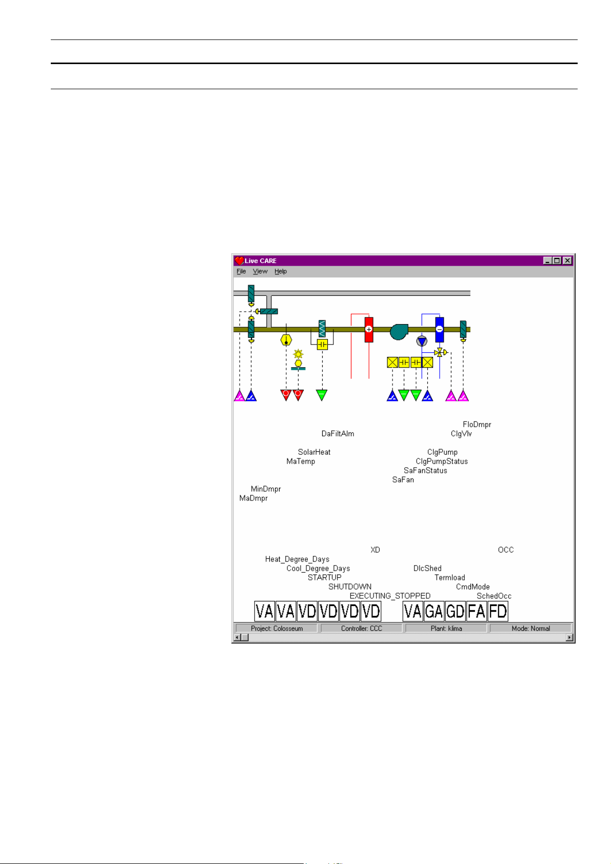
Watch applications at work Live CARE is an integral part of the CARE engineering system that allows online
access to controllers. When working with Live CARE, the application is presented to
the user in the same way as in the CARE engineering tool. This provides a convenient way to access and modify control parameters and data point values, thus
allowing easy plant start-up and fine-tuning.
Static simulator In addition to online access to controllers, the Live CARE simulator allows you to
check and tune controller applications by simulating the behavior of the controller.
This includes real-time, single-step or accelerated real-time simulation of:
• Time programs
• Control strategies
• Switching tables
• Data points
25
EN0B-0091GE51 R0708
Page 30

EXCEL 100/500/600
Manufactured for and on behalf of the Environmental and Combustion Controls Division of Honeywell Technologies Sàrl, Ecublens, Route du Bois 37, Switzerland by its Authorized Representative:
Automation and Control Solutions
Honeywell GmbH
Böblinger Strasse 17
71101 Schönaich / Germany
Phone: (49) 7031 63701
Fax: (49) 7031 637493
http://ecc.emea.honeywell.com
Subject to change without notice. Printed in Germany
EN0B-0091GE51 R0708
 Loading...