

Page 1
INTEGRATED ROOM CONTROL SOLUTIONS: FCU + LIGHT
2-wire FTT-10A LONWORKS® bus interface
LonMark® certified
Easily-accessible service button and service LED
Application can be configured to user-specific needs
via LNS™-based plug-in
Applications can be downloaded via L
flash memory (thus increasing flexibility)
ONWORKS into
Excel 12
PRODUCT DATA
FEATURES
Two-in-one controller for HVAC and lighting reduces
hardware costs and engineering effort (one
ONWORKS® node instead of two)
L
HVAC application supports three sequences (heat,
cool or change-over) and min. / max. control limits and
air-quality control
Light application supports three lamps. Up to two of
the three light loops can be constant light control
loops. Light switching can be done depending on light
level and occupancy (configurable via plug-in)
Unused inputs can be utilized for monitoring via the
ONWORKS network
L
Unused digital outputs (relay or triacs) can be
switched via L
Different kinds of HVAC actuators are supported
(PWM, thermal, staged, floating, or analog actuators)
Inputs / outputs can be freely assigned
DIN rail (wiring cabinet / fuse box) mounting and wall-
mounting supported
Different power supply variants available
Optional terminal protection covers for wall mounting
Optional swivel label holders for wiring information
ONWORKS
free
inputs
room
temp.
source
temp.
CO2
ppm
%
Excel 12
light #1 (corridor)
light #2 (corridor)
light #3 (window)
three-stage fan
sequence #1
sequence #2
sequence #3
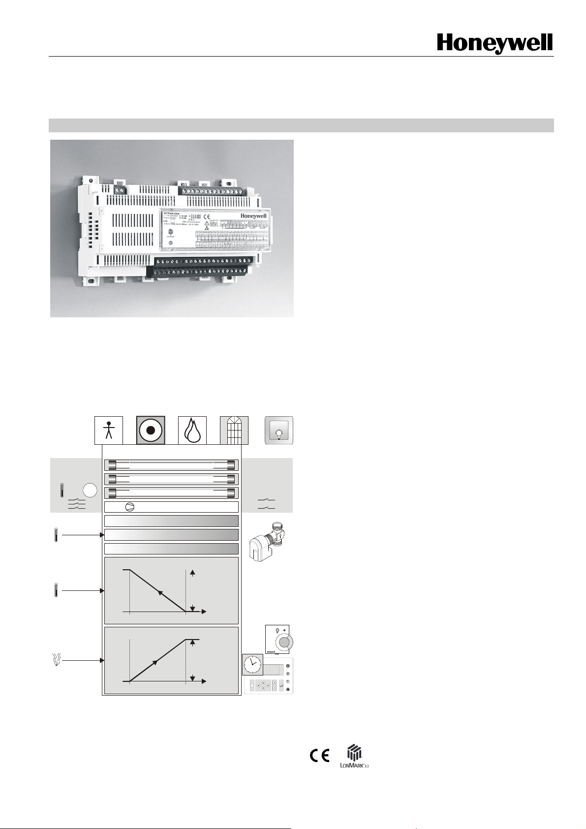
MAX. / MIN. CONTROL LIMIT
VALV E
POSITION
T
END
AIR-QUALITY CONTROL LIMIT
DAMPER
POSITION
CO2
START
Fig. 1. Functional overview
T
START
CO2
range of
range of
END
operation
operation
SOURCE
TEMP.
CO2
PPM
free
outputs
thermal, floating,
0...10V, PWM, or
staged actuators
12
9 3
6
C
C
GENERAL
The Excel 12 FCU + Light application is LONMARK® certified,
and can thus be used in all open L
Excel 12 supports the following LONMARK® objects:
one Node Object (LONMARK® object #0)
one Space Comfort Controller Fan Coil Object (profile
#8501)
three Lamp Actuator Objects (profile #3040)
one Occupancy Sensor Object (profile #1060)
two Open Loop Actuator Objects (L
A variety of hardware models with different power supplies
are available. Page 7 provides a detailed overview of the
available models.
Select the model fitting your particular needs.
The application can be downloaded into the Excel 12's
FLASH memory.
Honeywell's LNS™ plug-in allows you to configure the
application to match your specific requirements (e.g.
configure the heating / cooling sequences, the light
functionality and usage of otherwise unused inputs for
monitoring according to your needs).
The Excel 12 controller is designed for maintained zones.
ONWORKS® environments.
ONMARK® object #3)
® U.S. Registered Trademark
Copyright © 2010 Honeywell Inc. • All Rights Reserved EN0B-0470GE51 R0110
Page 2
EXCEL 12: FCU + LIGHT
A
APPLICATION
The Excel 12 Fan Coil Unit (FCU) + Light application supports
three HVAC sequences (HEAT, COOL, or CHANGEOVER)
with control limits, air-quality control, free inputs, free outputs,
and up to three lights.
The application is delivered together with the plug-in and must
be downloaded into the Excel 12 controller's flash memory
during start-up. The user can customize the application using
Honeywell's LNS™ plug-in with CARE or any LNS™ tool (e.g.
LonMaker for Windows™). Customizations can be saved /
reloaded for easy configuration of multiple devices.
Application Overview
HVAC Application:
Three sequences configurable for HEAT, COOL, and
CHANGEOVER
Support of thermal actuators, floating actuators, PWM,
0...10 Vdc, and staged output via triac outputs or relay
outputs
3-stage fan via triac outputs or relay outputs
Binary inputs for condensation, occupancy sensor,
window contact, etc.
Up to two limits (any combination of temperature limits
and/or air-quality limits)
Min./max. limits can be used to limit the sequence output
according to you requirements. The limits are valid only in
the occupancy mode.
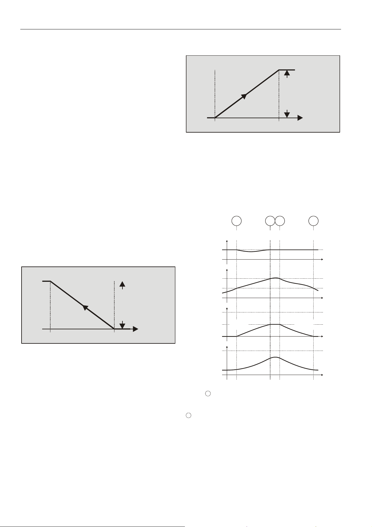
The example below shows that a heating valve will be
opened as soon as the source temperature drops below
T
. T
Start
Start, TEnd
configured using the plug-in.
MAX. / MIN. CONTROL LIMIT
VALVE
POSITION
T
END
NOTE: The min./max. limits have a higher priority than the
normal control output.
The air-quality can be controlled by opening a damper in
dependence on the CO2 level. The CO2 ramp is defined
by CO2
(entered using the plug-in).
Example:
CO2
CO2
range of operation = 50%
The damper starts opening as soon as the level of 1000 ppm
is reached. The maximum value (range of operation) is
reached at position CO2
START
START
= 2000 ppm
END
and the range of operation can be
range of
operation
SOURCE
T
START
Fig. 2. Minimum Heating Example
, CO2
, and the range of operation
END
= 1000 ppm
.
END
TEMP.
IR-QUALITY CONTROL LIMIT
range of
DAMPER
POSITION
CO2
START
CO2
Fig. 3. Air-quality control (example)
Example:
sequence 1: heating via radiator
sequence 2: cooling via damper
setpoint: 20 °C
CO2 control for sequence 2
CO2
CO2
= 1000 ppm
START
= 1500 ppm
END
range of operation = 50%
1 2
1000
ROOM TEMP.
SEQUENCE 2
SEQUENCE 1
20 °C
CO2 LEVEL
1500 ppm
1000 ppm
100%
50%
0%
100%
0%
ppm
<1000
(1000 ppm, 1500 ppm)
ppm
<1000
(1000 ppm, 1500 ppm)
ppm
DAMPER
OPENS
Fig. 4. Example
1
Before
:
CO2 level is OK → room temperature control, only
Temperature at 20 °C
1
CO2 level rises above CO2
CO2 level is too high, CO2 control starts with priority over
the temperature control
Damper opens, room temperature drops
Temperature drops to below 20 °C → heating sequence
starts heating
1500
ppm
>1500
>1500
START
ppm
ppm
operation
END
3
1500
ppm
(1000 ppm, 1500 ppm)
(1000 ppm, 1500 ppm)
DAMPER
CLOSES
:
4
1000
ppm
CO2
PPM
<1000
ppm
<1000
ppm
TIME
TIME
TIME
TIME
EN0B-0470GE51 R0110
2
Page 3
EXCEL 12: FCU + LIGHT
2
CO2 level rises above CO2
END
:
Damper reaches max. range of operation
Heating sequence achieves room temperature of 20 °C
3
CO2 level drops below CO2
END
:
Damper starts closing
Room temperature is maintained at setpoint value
4
CO2 level drops below CO2
CO2 level falls below CO2
T:
STAR
→ room temperature
START
control, only
Temperature is maintained at 20 °C
NOTE: The temperature limitation and the air-quality control
have priority over the temperature control.
Relative or absolute temperature setting via wall module.
Light Application:
Three times ON / OFF switching dependent on:
Occupancy
Internal light level: The light will be switched ON if the
light level drops below the "dark level" and it will be
switched OFF if it increases above the "bright level”.
The "dark level" and the "bright level” can be
configured via the plug-in.
NOTE: Do not select the “Auto Off Delay Timer” checkbox
insofar as this functionality is currently not supported.
Manual switching (via hardwired switches or
L
ONWORKS® wall module)
Two times dimming / constant light control for two lights
with just one sensor.
Dimming / constant light control is performed via analog
outputs (this requires an HFD [High-Frequency Device] for
dimming with 1...10 Vdc input). An additional relay is
required to switch the light ON/OFF.
Constant light control helps to save additional energy.
Normally, fluorescent tubes lose about 15% of their
illumination over their lifecycle. To compensate for this,
rooms are therefore usually dimensioned with 15% more
illumination than actually necessary. With constant light
control, the light level needs to be only 85% in order to
achieve the required brightness. Further savings and
comfort can be achieved if there is a constant light level in
the room and the light is automatically dimmed when more
outside light enters. The Excel 12 supports window
correction in order to reduce the light output of the window
light. This functionality can be configured via the plug-in.
Grouping of lights, e.g. switch three lights via a single
pushbutton.
Soft ON/OFF switching for dimmable lamps.
Light sensor: The light intensities typically encountered in
everyday life are listed in Table 1, while Table 2 presents
the recommended light levels in various environments as
set forth by DIN5035.
NOTE: One lux is equivalent to 0.0929 foot-candle.
Refer also to the plug-in help information for details.
Table 1. Typical light intensities
ambient conditions intensity (lux)
summer day, cloudless 100,000
summer day, cloudy 20,000
winter day, cloudy 400
night, with full moon 0.3
Table 2. Recommended light intensities (DIN5035)
area intensity (lux)
storage rooms 50...200
washrooms, cloakrooms, technical
rooms, corridors
100
office rooms (near windows) 300
office rooms (minimal outside light) 500
open-plan office rooms 750
schools (daytime) 300
night schools 500
gymnasiums 200
show rooms 300
commercial kitchens 500
NOTE: The intensity level depends on the sensor type and
the mounting location.
NOTE: The indoor light sensor must be suitable for sensing
artificial light, and should be mounted more towards
the corridor.
Free Inputs for Monitoring:
Unused inputs can be used for monitoring. This
application supports the following free inputs:
one temperature input (NTC20k)
one percentage input (0..10 V or 2..10 V)
three binary inputs
The input values are communicated via nvoXL12Status.
Free Binary Outputs Can Be Switched Via L
ONWORKS:
Up to two unused digital outputs (triac or relay outputs)
may be switched via L
ONWORKS® (nviFreeOutput[0/1]).
Occupancy Modes:
Occupied mode: The Excel 12 operates according to the
"occupied" heating and cooling set-points.
Bypass: After the bypass button of a hardwired wall
module has been pressed or when corresponding data is
received via the L
ONWORKS® network, the Excel 12
operates temporarily according to the "occupied" heating
and cooling set-points. When the bypass time has
elapsed, the controller reverts to scheduled mode. The
bypass time can be configured via plug-in.
Standby mode: The Excel 12 operates according to the
"standby" heating and cooling set-points.
Unoccupied mode: The Excel 12 operates according to
the "unoccupied" heating and cooling set-points.
3 EN0B-0470GE51 R0110
Page 4

EXCEL 12: FCU + LIGHT
Occupancy sensor: The occupancy sensor is used for the
HVAC and light application. Hardwired and L
ONWORKS®
occupancy sensors are supported. The occupancy sensor
determines the effective occupancy mode during
scheduled occupied periods (time program with
occupancy schedule runs on a different controller connected to the L
ONWORKS® network). Depending upon the
actual occupancy sensor state, the effective mode will be
either "occupied" or "standby."
Wall Modules:
L
ONWORKS® wall modules
Hardwired wall modules (e.g. T7460, T7560)
Wireless wall modules (e.g. W7070+T7270 or RT7070)
Master / Slave Functionality:
The master / slave functionality allows easy adaptation to
changed room usage.
The sequences and the outputs of the slave controller must
be configured in the same way as the master (e.g. sequence
1: heat, actuator type: thermal).
The temperature limit functionality and the air-quality functionality shall not be used in the slave controller if there is an
EnergyHoldOff binding from the slave to the master.
nviEnergyHoldOff
SEQUENCE 0, POSITION *1
SEQUENCE 1, POSITION *1
MASTER
SEQUENCE 2, POSITION *1
FANSPEED, POSITION *2
OCCUPANCY MODE
HEATING/COOLING POSITION *3
SLAVE
nviSequence [ 0]
nviSequence [ 1]
nviSequence [ 2]
nvoFanSpeedCmd
nviOccManCmd
nviApplicMode
nvoEnergyHoldOff
master
Excel 12
*1: ONLY IF SEQUENCE IS CONFIGURED
*2: ONLY IF FAN IS CONFIGURED
*3: ONLY IF CHANGEOVER SEQUENCE IS CONFIGURED
nvoSequence [0]
nvoSequence [1]
nvoSequence [2]
nvoFanSpeed
nvoEffectOcc
nvoHeatCool
THIS NV ALWAYS BINDS THE MASTER XL12 TO THE FINAL SLAVE XL12.
Excel 12
Excel 12
WINDOW CONTACTWINDOW CONTACT
Excel 12
WINDOW CONTACT
slave
slave
slave
nvoEnergyHoldOff
nviEnergyHoldOff
Fig. 5. Master/slave functionality and window contact
master
Excel 12
nvoLampValue nviLampValue
LIGHT
nviLampValue
slave
Excel 12
slave
Excel 12
master
Excel 12
THIS NV ALWAYS BINDS THE MASTER XL12 TO THE FINAL SLAVE XL12.
nvoLampValue nvoLampValuenviLampValuenviLampValue
LIGHT LIGHT
nvoLampValue nviLampValue
slave
Excel 12
slave
Excel 12
LIGHT
Fig. 7. All lights switched on via any pushbutton
NOTE: This binding shall not be used for applications
involving dimming or constant light control. Binding
via L
ONWORKS results in a short delay between the
switching of the different lamps. Pressing the
pushbutton repeatedly and rapidly may cause toggle
effects.
Benefits of Integrated Room Control
The Excel 12 functionality provides you with a number of
significant advantages:
Considerable Reduction in Energy Consumption:
25...75% savings on electrical energy consumption for
illumination.
Decreased heat generated by electric lights, thus reducing
cooling energy requirements.
Increased Convenience:
Occupancy sensor switches the light ON/OFF
automatically.
Constant light control always provides the correct lighting.
Optional air-quality control in the occupancy mode.
Wireless control via ZAPP (see ZAPP System
Engineering, EN0B-0286GE51).
Increased Flexibility:
Flexible room usage if a L
ZAPP (wireless remote control) is used.
Reduced Engineering Effort / Expenses:
Just one L
ONWORKS® node (instead of two) is required to
cover HVAC and Light.
reduced engineering and installation effort (e.g. wiring,
binding, commissioning, etc.)
reduced integration effort
lower cost due to reduced number of LNS™ credits
lower hardware total loop costs
ONWORKS® wall module or
Fig. 6. All lights switched via master pushbutton
NOTE: Binding via LONWORKS results in a short delay
between the switching of the different lamps.
EN0B-0470GE51 R0110
4
Page 5

EXCEL 12: FCU + LIGHT
Interoperability
See also section “Approvals, Certifications, and Standards”
on page 8.
Device Configuration
The controller is configured using Honeywell's LNS™ plug-in.
The plug-in can be started from CARE 4.0 or any LNS™ tool
(e.g. LonMaker for Windows™).
LONMARK® Objects Network Variables
The Excel 12 supports the following LONMARK® objects:
one node object (see Fig. 11)
one space comfort controller object (#8501 SCC – Fan
Coil) (see Fig. 12)
three lamp actuator objects (#3040) (see Fig. 8)
one occupancy sensor object (#1060) (see Fig. 9)
two open loop actuator objects (#3) (see Fig. 10)
See also Table 5 through Table 8 on page 9.
Lamp Actuator Object
LonMark Lamp Actuator Object
(profile #3040)
Open Loop Actuator Object
LonMark Open Loop
Actuator Object (#3)
nviFreeOutput
SNVT_switch
mandatory
1
Network
Variables
Fig. 10. Open Loop Actuator Object
Node Object
Node Object
(LonMark Object type no. 0)
nviRequest
SNVT_obj_request
mandatory
1
Network
Var iab le s
optional
Network
Variables
nvoStatus
SNVT_obj_status
nvoFileDirectory
SNVT_address
nvoHwType
UNVT_HWType
2
8
9
nviLampValue
SNVT_switch
nviOccManCmd
SNVT_occupancy
nviLuxLight
SNVT_lux
nviOccSchedule
SNVT_tod_event
nviOccSensor
SNVT_occupancy
1
mandatory
Network
Var iab les
Network
Var iab le s
shared
among Objects
Fig. 8. Lamp Actuator Object
Occupancy Sensor Object
LonMark Occupancy
Sensor Object
(profile #1060)
mandatory
Network
Var iab le s
Fig. 9. Occupancy Sensor Object
nvoLampValueFb
SNVT_switch
nvoOccSensor
SNVT_occupancy
nvoHwIdentify
UNVT_HWIdentify
nvoDiagnostic
UNVT_Diagnostic
nvoXL12Status
UNVT_XL12Status
2
nviDiagnRequest
UNVT_DiagRequest
nviLuxLight
SNVT_lux
11
14
Manufacturer-
specific
(device-related)
Network
Variables
shared
among Objects
Configuration
Parameter
Value File
10
12
13
Fig. 11. Node Object
1
5 EN0B-0470GE51 R0110
Page 6

EXCEL 12: FCU + LIGHT
Space Comfort Controller Object
Space Comfort Controller -
Fan Coil Object #8501
nviSpaceTemp
SNVT_temp_p
nviSetPoint
SNVT_temp_p
nviSetptOffset
SNVT_temp_p
nviOccSchedule
SNVT_tod_event
nviOccManCmd
SNVT_occupancy
nviOccSensor
SNVT_occupancy
nviApplicMode
SNVT_hvac_mode
nviFanSpeedCmd
SNVT_switch
nviEnergyHoldOff
SNVT_switch
SCPTsetPnts
SCPTbypassTime
nviSequence[0]
nviSequence[1]
SNVT_lev_percent
nviSequence[2]
SNVT_lev_percent
SNVT_lev_percent
|1 |26
|2
|3
|5
|6
|7
Optional Mandatory
|8
|10
|14
Manufacturer-
Specific
nvoSpaceTemp
SNVT_temp_p
nvoUnitStatus
SNVT_hvac_status
nvoEffectOcc
SNVT_occupancy
nvoHeatCool
SNVT_hvac_mode
nvoFanSpeed
SNVT_switch
nvoEnergyHoldOff
SNVT_switch
nvoSequence[0]
nvoSequence[1]
SNVT_lev_percent
nvoSequence[2]
SNVT_lev_percent
SNVT_lev_percent
|27
|29
|30
|33
|49
LONWORKS® Network Interface
The Excel 12 communicates within the LONWORKS® network
at a rate of 78 kbs via an FTT-10A Free Topology
Transceiver, which provides transformer isolation; the bus
wiring is thus insensitive to polarity.
Devices so equipped can be wired in daisy chain, star, loop,
or any combination thereof as long as the max. wire length
requirements are met. The recommended configuration is a
daisy chain with two termination modules. This layout allows
for max. bus length and has the highest communication
reliability, particularly when adding on to an existing bus.
Refer also to http://www.echelon.com
Configuration and Binding
Configuration is performed using Honeywell's LNS™ plug-in,
which can be started from CARE 4.0 or any LNS™ tool (e.g.
LonMaker for Windows™). Likewise, binding is performed
using CARE 4.0 or any LNS™ tool.
LONWORKS® Service Button and LED
All models feature a LONWORKS® service button (accessible
from the outside on top of the module).
The service pin message is broadcast:
whenever the L
after each reset due to power-up, software reset;
if a hardwired pushbutton for lighting is pushed for more
than 10 seconds.
See also Excel 12 Installation Instructions (EN1B-0201GE51)
for more-detailed information.
All models feature a L
missioning and troubleshooting. The service LED displays
numerous different behaviors indicating various module states
for use in troubleshooting (see also Excel 12 Installation
Instructions).
ONWORKS® service button is pressed;
ONWORKS® service LED for com-
nviSrcTemp[0]
nviSrcTemp[1]
SNVT_temp_p
SNVT_temp_p
Fig. 12. FCU Controller Object
EN0B-0470GE51 R0110
6
Page 7

Models
EXCEL 12: FCU + LIGHT
Table 3. Overview of Excel 12 models
W7704A1004*1
W7704B1002*1
W7704C1000*1
W7704D1008
W7704D1016
W7704F1003*1*2
short housing
long housing
24 Vac
230 Vac
binary input 1
binary input 2
binary input 3
binary input 4
relay 1 (N-O)
relay 2 (N-O)
relay 3 (N-O)
relay 4 (C-O)
relay 5 (C-O)
triac 1
triac 2
triac 3
traic 4
triac 5
triac 6
wall module LED
output
AI1 (NTC20k + V)
AI2 (NTC20k)
AI3 (fan speed /
bypass)
AI4 (setpoint)
AI5 (NTC20k + V)
X X X X X X X X X X X X X X X X X X X X X X X X X
X X X X X X X X X X X X X X X X X X X X X X X X X X X
X X X X X X X X X X X X X X X X X X X X X X
X X X X X X XXXXXXXXXXX X X X X X XXXXX
X XX X X X XXXXXXXXXXX X X X X X XXXXX
X X X X X X X X X X X X X X
*1 These hardware versions have been discontinued.
*2 The hardware variant W7704F1003 is cost-optimized for light control and does not support hardwired wall modules.
Long and Short Housings
Models powered with line power (W7704A, B, and D1016) are
equipped with a built-in transformer and feature a long
housing (W X L X H = 180 X 76 X 110 mm).
Models powered with 24 Vac (W7704C, and D1008) require
an external 24 Vac power supply and feature a short housing
(W X L X H = 126 X 76 X 110 mm).
Binary Inputs
The Excel 12 is equipped with four dry-contact binary inputs.
The binary inputs are fast (the signal must be stable for at
least 25 ms). These inputs are often used for light
pushbuttons.
Binary Outputs
The triac outputs or relay outputs can be configured for
different functions.
Relay Outputs
The Excel 12 is equipped with up to two change-over (C-O)
relays and up to three normally-open (N-O) relays.
Hardware Limits
In order to ensure a reliable contact, a min. current of
50 mA is required.
The normally-open contacts are designed for a max.
continuous current of 16 A. The normally-closed contacts
Hardware Limits for Excel 12 with Line Power Supply
Low signal: 0 V; high signal: 24 Vac
Max. 250 mA continuous current in sum for all triac
outputs together
550 mA for max. 10 sec.
cos > 0.5
Hardware Limits for Excel 12 with 24 Vac Power Supply
Low signal: 0 V; high signal: 24 Vac
Max. 500 mA continuous current in sum for all triac
outputs together
800 mA for max. 10 sec.
cos > 0.5
NOTE: For controlling thermal actuators, we recommend
using the 24 Vac models, which provide more
current.
Analog Outputs
The Excel 12 is equipped with up to two 0...11 Vdc analog
outputs each of which can drive a max. of ±1.1 mA.
Analog Inputs
The Excel 12 is equipped with up to 7 analog inputs, all of
which can be configured as slow binary inputs (in which case
the signal must be stable for at least 1.25 sec) for the
detection of a slow signals (e.g. from a window contact).
are designed for a max. continuous current of 1 A.
In order to reduce the build-up of heat in the housing, the
max. combined allowable current flowing through all relays
simultaneously is 24 A (continuous).
The max. peak in-rush current (20 ms) at the normally-
open contact is 80 A.
Triac Outputs
The Excel 12 is equipped with up to six triac outputs.
AI6 (NTC20k)
AI7 (NTC20k + V)
AO1 (0...10 Vdc)
AO2 (0...10 Vdc)
7 EN0B-0470GE51 R0110
Page 8

EXCEL 12: FCU + LIGHT
Table 4. Analog input usage (with wall modules)
analog input voltage NTC wall module
AI1 X X e.g. CO2 or humidity
AI2 X room temperature1
AI3 fan speed or bypass2
AI4 setpoint3
AI5 X X e.g. CO2 or humidity
AI6 X
AI7 X X e.g. CO2 or humidity
1
For all NTC inputs, temperatures of -50...-45 °C are interpreted as
being due to a sensor break, and temperatures of +145...+155 °C
are interpreted as being due to a sensor short-circuit.
2
A contact open for 10 seconds is interpreted as a sensor failure.
3
A resistance of > 15k is interpreted as being due to a sensor
break, a resistance of < 100 is interpreted as being due to a
sensor short-circuit.
Accessories
Swivel Label Holders
For short or long housings (required for modules equipped
with manual override switches).
24 Vac models (short), order no.: XAL_LAB_S
line power supply models (long), order no.: XAL_LAB_L
Terminal Protection Covers
For short or long housings (required for wall/ceiling mounting).
24 Vac models (short), order no.: XAL_COV_S
line power supply models (long), order no.: XAL_COV_L
LONWORKS® Termination
One or two LONWORKS® terminations are required, depending
on the given LonWorks bus layout.
Two different L
L
ONWORKS® termination module,
order no.: 209541B
LONWORKS® connection / termination module (can be
mounted on DIN rails and in fuse boxes),
order no.: XAL-Term
removable screw-type
3-pole terminal block
Fig. 13. LonWorks® connection and termination module
ONWORKS® terminations are available:
l
l
e
w
y
e
n
o
H
m
r
e
T
-
L
A
X
4
3
L
L
O
O
N
N
shield shield
plug-in
jumper
3
4
1
06
Termination
5
LON
FTT/LPT Bus
FTT/LPT Free
Park Position
Approvals, Certifications, and Standards
Approvals and Certifications
CE-approved
Certified as per LonMark® Application Layer
Guidelines V 3.3, thus interoperable with all other
devices in open L
ONWORKS® networks (incl. 3
devices)
EUBAC-certified as follows:
W7704D1016:
W7704D1008:
eu.bac
020893
Cert
eu.bac
020896
Cert
Classification according to EN60730-1
Environmental conditions: For use in home (residential,
commercial, and light-industrial)
environments
Pollution degree: Class 2
Protection against shock: Class 0 (without terminal covers)
Class II (with terminal covers)
Software class: Class A
Classification according to EN60529
(Degree of Protection Provided by Enclosures)
Without terminal covers: IP20
With terminal covers: IP30
Ambient Environmental Limits
Operating temperature: 0 … +50 °C at 5…90% r.H.
Storage temperature: -30 … +70 °C at 5…90% r.H.
W7704D1008, W7704D1016 Temperature CA
Chilled ceiling: 0.5 K
Electric convector: 0.3 K
Electric floor heating: 1.2 K
Radiator heating: 0.5 K
FCU heating mode: 0.4 K
FCU cooling mode: 0.2 K
(min. Temperature Control Accuracy values requested by
EUBAC: ≤ 1.4 K for hot water radiator heating, fan coil unit,
VAV, and chilled ceiling applications; ≤ 1.8 K for water floor
heating, electric convector, electric floor heating, and electric
ceiling heating applications)
Applicable Literature
Excel 12 Installation Instructions (EN1B-0201GE51)
Excel 50/500 L
0270GE51)
Excel 10 FTT/LPT 209541B Termination Module
Installation Instructions (95-7554)
ZAPP System Engineering (EN0B-0286GE51)
XL12 / XL Smart I/O Plug-in Installation Guide (EN0B-0294
GE51)
Honeywell's XL12 / Excel Smart I/O plug-in help
ONWORKS® Mechanisms (EN0B-
rd
-party
EN0B-0470GE51 R0110
8
Page 9

EXCEL 12: FCU + LIGHT
NETWORK INTERFACE
The following tables list the NV's associated with the various
L
ONMARK® objects serving as network interfaces to the Excel
12 FCU + Light application.
Table 5. NV's associated with Space Comfort Controller
FCU Object (profile # 8051)
name type heartbeat
nviSpaceTemp SNVT_temp_p yes
nviSetPoint SNVT_temp_p no
nviSetptOffset SNVT_temp_p yes
nviOccSchedule SNVT_tod_event yes
nviOccManCmd SNVT_occupancy no
nviOccSensor SNVT_occupancy yes
nviApplicMode SNVT_hvac_mode yes
nviFanSpeedCmd SNVT_switch no
nviEnergyHoldOff SNVT_switch yes
nviEmergOverride SNVT_hvac_emerg no
nviSrcTemp[2] SNVT_temp_p yes
nviSequence[3] SNVT_lev_percent yes
nvoSequence[3] SNVT_lev_percent yes
nvoSpaceTemp SNVT_temp_p yes
nvoUnitStatus SNVT_hvac_status yes
nvoEffectOcc SNVT_occupancy no
nvoHeatCool SNVT_hvac_mode yes
nvoFanSpeed SNVT_switch yes
nvoEnergyHoldOff SNVT_switch yes
Table 6. NV's associated with Occupancy Sensor Object
(profile #1060)
name type heartbeat
nvoOccSensor SNVT_occupancy yes
Table 7. NV's associated with Lamp Actuator Object
(profile #3040)
name type heartbeat
nviLampValue[3] SNVT_switch no
nvoLampValueFb[3] SNVT_switch no
Table 8. NV's associated with the Node Object
(LONMARK® object #0)
name type heartbeat
nviRequest SNVT_obj_request no
nvoStatus SNVT_obj_status yes
nvoFileDirectory SNVT_address no
nviDiagnRequest UNVT_DiagRequest no
nvoDiagnostic UNVT_Diagnostic no
nvoXL12Status UNVT_XL12Status no
nviLuxLight SNVT_lux no
nvoHwType UNVT_HwType n/a
nvoHwIdentify UNVT_HWIdentify n/a
Table 9. NV's associated with Open Loop Actuator Object
ONMARK® object #3)
(L
name type heartbeat
nviFreeOutput[2] SNVT_switch no
Note: Device Resource Files are included in the plug-in
package and facilitate the handling of UNVTs
9 EN0B-0470GE51 R0110
Page 10

EXCEL 12: FCU + LIGHT
DIMENSIONS
swivel label
holders (optional)
terminal protection
cover (optional)
terminal protection
cover (optional)
cut-out tabs
(to expose terminal pins)
leverage slot
LonWorks
service button
long housing (with built-in transformer): 180 m (7-7/8 in.)
Short housing (without transformer): 126 mm (4-15/16 in.)
LonWorks
service LED
ventilation slits
Manufactured for and on behalf of the Environmental and Combustion Controls Division of Honeywell Technologies Sàrl, Rolle, Z.A. La Pièce 16, Switzerland by its Authorized Representative:
Automation and Control Solutions
Honeywell GmbH
Böblinger Strasse 17
71101 Schönaich
Germany
Phone: (49) 7031 63701
Fax: (49) 7031 637493
http://ecc.emea.honeywell.com
Subject to change without notice. Printed in Germany
EN0B-0470GE51 R0110
 Loading...