

Honeywell Excel 5000 System, Excel 10 LPT 209541B, Excel 10 FTT 209541B Installation Instructions Manual
Excel 10 FTT/LPT 209541B
BEFORE INSTALLATION
E-Bus Free Topology Transceiver (FTT) / Linked Power
Transceiver (LPT) networks require termination. Depending
on the network topology, one or more FTT/LPT Termination
Modules may be required, see Fig. 1. If an FTT Repeater or a
LPT device is required in the network, their on-board
terminators can be used in place of the 209541B Termination
Module. Refer to the
for complete rules on network topology and termination
module locations. Refer to the
Installation Instructions
enabling the on-board network terminators.
FTT/LPT networks are very flexible and convenient for
installation and maintenance. However it is imperative to
carefully plan the network layout, and create and maintain
accurate layout documentation.
E-Bus Wiring Guidelines
, form 74-2865,
Q7740A,B FTT Repeater
, form 95-7555, for information on
TERMINATION MODULE
INSTALLATION INSTRUCTIONS
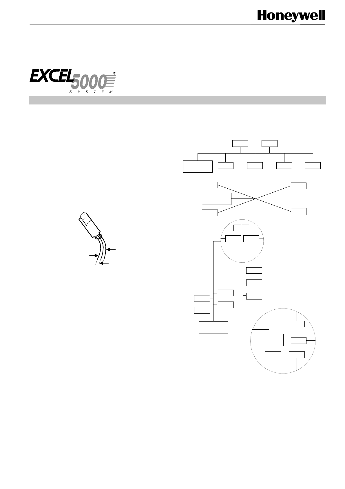
Double termination is only applicable when a network is wired
in a daisy-chain topology and the total wire length is greater
than 1640 ft (500m). Refer to the
form 74-2865, for complete rules on network topology and
termination module locations.
DEVICE
TERMINATION
MODULE
DEVICE DEVICE DEVICE
SINGLY TERMINATED
DEVICE
TERMINATION
MODULE
DEVICE
DEVICE
E-Bus Wiring Guidelines
DEVICE
DEVICE
STAR
DEVICE
,
DEVICE
YELLOW
BROWN ORANGE
Fig. 1. 209541B FTT/LPT Termination Module
.
INSTALLATION
The FTT/LPT Termination Module can be attached to the
network at a controller node (the easiest place); In a wall
module that is attached to standard utility junction box (the
module will not fit in a 60 mm junction box); At a wiring
junction (using wire nuts). See Fig. 6 when connecting two
wires at a controller or wall module terminal. If the
termination module must be located at a surface mounted
wall module, and does not fit inside the wall module housing,
extend a pair of E-Bus wires from the wall module back to the
nearest junction box or controller, and wire in the termination
module. The module has three lead wires, but only two are
attached to the E-Bus network .To install the termination
module, connect the brown and yellow wires to the E-Bus
when the network requires
brown and orange to the E-Bus when the network requires
double termination
. In either case, always cover the unused
wire with a wire nut to prevent potential grounding problems.
As with other E-Bus connections, polarity is not important.
Fig. 2 shows the module attached to typical FTT/LPT network
topologies for a
single termination
connection of the module for a single termination network.
Fig. 4 shows the modules attached to a typical FTT/LPT
network for a
double termination
connection of the modules for a double termination network.
single termination
; connect the
. Fig. 3 shows the physical
. Fig. 5 shows the physical
DEVICE
DEVICE
DEVICE
DEVICE
TERMINATION
MODULE
DEVICEDEVICE
DEVICE
DEVICEDEVICE
LOOP
DEVICE
DEVICE
TERMINATION
MODULE
MIXED
DEVICE
DEVICE
DEVICE
Fig. 2. FTT/LPT termination module wiring for
termination
network topologies
.
single
® U.S. Registered Trademark
Copyright © 1997 Honeywell Inc. • All Rights Reserved 95-7554
EXCEL 10 FTT 209541B TERMINATION MODULE
E-BUS
]
BROWN
ORANGE
YELLOW
Fig. 3. Physical connection of module for a
termination
network
.
single
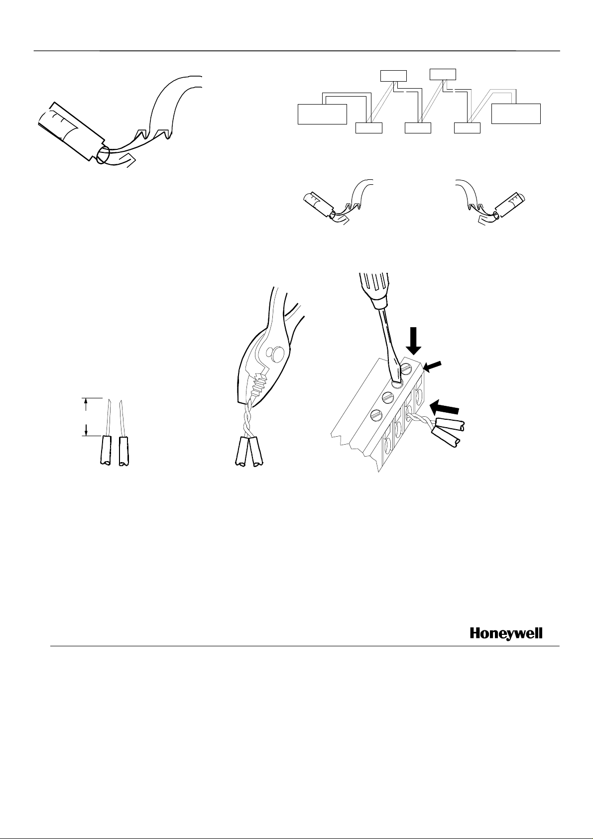
DEVICE
~
(DAISY CHAINED)
~
TERMINATION
MODULE
DEVICE
~
(DAISY CHAINED)
DEVICE DEVICE DEVICE
~
Fig. 4. FTT/LPT termination module wiring for
network topology
E-BUS
]
E-BUS
ORANGE
.
[
BROWN
YELLOW
BROWN
termination
ORANGE
YELLOW
Fig. 5. Physical connection of modules for a
termination
network
CONTROLLER OR
WALL MODULE
E-BUS
CONNECTOR
TERMINALS
.
TERMINATION
MODULE
double
double
1/2
(13)
STRIP 1/2 IN. (13 MM) FROM WIRES
1. 2. TWIST WIRES TOGETHER
TO BE ATTACHED AT ONE TERMINAL.
WITH PLIERS (A MINIMUM
OF THREE TURNS).
3.
CUT TWISTED END OF WIRES TO 3/16 IN. (5 MM)
BEFORE INSERTING INTO TERMINAL AND TIGHTENING
SCREW. THEN PULL ON EACH WIRE IN ALL TERMINALS
TO CHECK FOR GOOD MECHANICAL CONNECTION.
M8945JD
Fig. 6. Attaching two wires at controller or wall module terminals.
NOTE: The termination module is outside of the scope of
the EMC directive and therefore does not require
CE marking. This is because the termination
module is an RC filter (with only passive
components.
Home and Building Control Home and Building Control Products Helping You Control Your World
Honeywell Inc. Honeywell AG
Honeywell Plaza Böblinger Straße 17
P.O. Box 524 D-71101 Schönaich
Minneapolis, MN 55408-0524 Phone (49-7031) 637-01
Fax (49-7031) 637-493
95-7554 Rev. 2-97
Printed in USA.
 Loading...