

Page 1

Excel 50/100/500/600/800
HONEYWELL EXCEL 5000 OPEN SYSTEM
CONTROLLERS
SOFTWARE DESCRIPTION
® U.S. Registered Trademark EN2B-0092GE51 R0709
Copyright © 2009 Honeywell Inc. • All rights reserved
Page 2

EXCEL 50/100/500/600/800
Trademark Information Echelon, LON, L
LonTalk, LonUsers, LonPoint, Neuron, 3120, 3150, the Echelon logo, the LONMARK
logo, and the LonUsers logo are trademarks of Echelon Corporation registered in
the United States and other countries. LonLink, LonResponse, LonSupport, and
LonMaker are trademarks of Echelon Corporation.
ONMARK, LONWORKS, LonBuilder, NodeBuilder, LonManager,
EN2B-0092GE51 R0709
Page 3

EXCEL 50/100/500/600
CONTENTS
Revision overview ........................................................................................................................................................................ 5
System Overview.......................................................................................................................................................................... 6
Datapoints..................................................................................................................................................................................... 9
Physical Datapoints .................................................................................................. 9
Flexible Datapoints ................................................................................................. 10
Pseudo Datapoints ................................................................................................. 10
Global Datapoints ................................................................................................... 11
Mapped Datapoints (V2.04.xx or higher) ................................................................ 12
Attributes .................................................................................................................................................................................... 13
Access Level........................................................................................................... 13
Acknowledge Alarm (V2.04.xx or higher)................................................................ 13
Active State (prior to V2.04.x)................................................................................. 14
Active State (Excel 800) ......................................................................................... 14
Alarm Delay ............................................................................................................ 15
Alarm Suppression ................................................................................................. 15
Alarm Status (prior to V2.04.x)................................................................................ 15
Alarm Status (V2.04.xx or higher)........................................................................... 16
Alarm Type ............................................................................................................. 16
Alarm Definition ...................................................................................................... 17
Cycle Count ............................................................................................................ 18
Delay Time Switching Up........................................................................................ 18
Delay Time Switching Down ................................................................................... 18
Descriptors ............................................................................................................. 18
Engineering Unit ..................................................................................................... 19
Feedback Delay...................................................................................................... 19
High/Low Alarm/Warning Limits.............................................................................. 19
Hours Run .............................................................................................................. 20
Hours Run Log........................................................................................................ 20
Hours Since Serviced ............................................................................................. 20
Hysteresis............................................................................................................... 21
Alarm Hysteresis ................................................................................................ 21
Trend Hysteresis ................................................................................................ 22
Broadcast Hysteresis ......................................................................................... 22
Intrinsic Hysteresis for Analog Input Signals ...................................................... 23
Input/Output Status Text (prior to V2.04.xx) ........................................................... 24
Input/Output Status Text (V2.04.xx or higher)......................................................... 24
Interval Count ......................................................................................................... 24
Interval Limit ........................................................................................................... 24
I/O Characteristic.................................................................................................... 25
Pull-Up Resistor Handling....................................................................................... 26
Last Change ........................................................................................................... 27
LED Mode (XF823x, XFL823x, and XFx830x modules) ......................................... 27
Maintenance Alarm................................................................................................. 27
Manual Value.......................................................................................................... 27
Network Variable (V2.04.xx or higher) .................................................................... 28
Normally Open/Normally Closed (V2.04.xx or higher) ............................................ 28
Motor Run Time ...................................................................................................... 29
Off Phase................................................................................................................ 29
Operating Mode ...................................................................................................... 30
Output Type............................................................................................................ 32
Subtype.............................................................................................................. 32
Point Alarms ........................................................................................................... 32
Pulse Duration ........................................................................................................ 32
Safety Position (XFx822x, XFx824x, and XFx830x modules)................................. 32
Scaling Factor......................................................................................................... 33
Sensor Offset.......................................................................................................... 33
Suppress Point ....................................................................................................... 34
Switching Down ...................................................................................................... 34
3 EN2B-0092GE51 R0709
Page 4

EXCEL 50/100/500/600/800
Switch-On Counter ..................................................................................................34
Technical Address ...................................................................................................34
Trend Logging .........................................................................................................35
Value Hysteresis .................................................................................................36
Trend Cycle (V2.03.x) .........................................................................................36
User Address...........................................................................................................37
Value .......................................................................................................................37
Write Protection.......................................................................................................37
List of Datapoint Attributes ......................................................................................39
Time Programs ............................................................................................................................................................................42
Structure..................................................................................................................42
Individual Time Programs........................................................................................42
Daily Program .....................................................................................................42
Weekly Program .................................................................................................43
Annual Program ..................................................................................................44
Special Day List ..................................................................................................44
The "TODAY" Function .......................................................................................44
Generating a Time Program ....................................................................................45
Alarm Handling............................................................................................................................................................................46
Point Alarms ............................................................................................................46
System Alarms ........................................................................................................47
System Alarms Suppression (V. 2.04.xx or higher).............................................51
User Program Alarms ..............................................................................................52
Data Storage ...........................................................................................................52
Alarms Sent across the System Bus...................................................................52
Test Mode (V2.03.x).....................................................................................................................................................................53
Communication ...........................................................................................................................................................................53
System Bus .............................................................................................................53
Access ................................................................................................................54
Bus Initialization ..................................................................................................54
Bus Communication............................................................................................54
I/O Runtime Synchronization ..............................................................................55
Initialization of Distributed I/O Modules ...............................................................55
New Bus Devices................................................................................................55
Network-Wide Controller Time Synchronization..................................................56
Point Refreshing .................................................................................................56
PC Communication..................................................................................................56
Excel IRC ................................................................................................................56
Remote Communication ..........................................................................................56
Remote Trending (dial-up).......................................................................................58
General ...............................................................................................................58
Controller Firmware 2.03.xx and Higher..............................................................58
Controller Firmware 2.04.xx and Higher..............................................................59
Excel 800 ............................................................................................................60
MODEMFAQ ...........................................................................................................61
Index.............................................................................................................................................................................................62
EN2B-0092GE51 R0709 4
Page 5

EXCEL 50/100/500/600/800
REVISION OVERVIEW
The following pages have been changed from the previous issue of this document:
page change
2
21 Table 10 “Pull-up resistor handling” revised
22
27
52 Fig. 1. “Remote Modem Connection” revised
Fig. 1 “Controllers and their supported firmware versions”
revised
Section “LED Mode (XF823x, XFL823x, and XFx830x
modules) revised
Section “Safety Position (XFx822x, XFx824x, and XFx830x
modules)” revised
5 EN2B-0092GE51 R0709
Page 6

EXCEL 50/100/500/600/800
SYSTEM OVERVIEW
General Excel 50/500/800 controllers support both LONWORKS communication and the
Honeywell proprietary C-Bus communication.
ONWORKS-related information is described in the LONWORKS Mechanism
All L
document (EN0B-0270GE51).
Excel 50/100/500/600/800 is a control and monitoring system specially designed for
use in buildings. These Excel controllers use the latest Direct Digital Control (DDC)
technology. Excel 50/500/800 controllers are also capable of communicating on an
open Echelon® L
particularly well-suited to controlling buildings such as schools, hotels, offices, and
hospitals. Excel 50/100 controllers differ from Excel 500/600/800 controllers in
having a fixed input/output configuration.
Excel 50 controllers have a smaller fixed input/output configuration, and are designed for smaller buildings such as restaurants, shops, banks, and offices.
Excel 50/100/500/600/800 functions are:
• Heating control
• Air conditioning control
• Energy management
• Energy optimization
• Other building management functionality
Software The Excel 50/100/500/600/800 system includes a comprehensive software package
specially designed to meet the requirements of application engineers. It comprises
the following:
• Datapoint description
• Time program
• Alarm handling
• Password protection
The software package comes with all the files listed. The menu-driven format allows
quick and easy operation.
ONWORKS® network. Excel 50/100/500/600/800 controllers are
Firmware version number All information appearing in this Software Description is valid for firmware versions
V1.3.xx and earlier. All information, functions, and attributes valid for newer
firmware versions (V1.5.xx or higher) are marked by the corresponding version
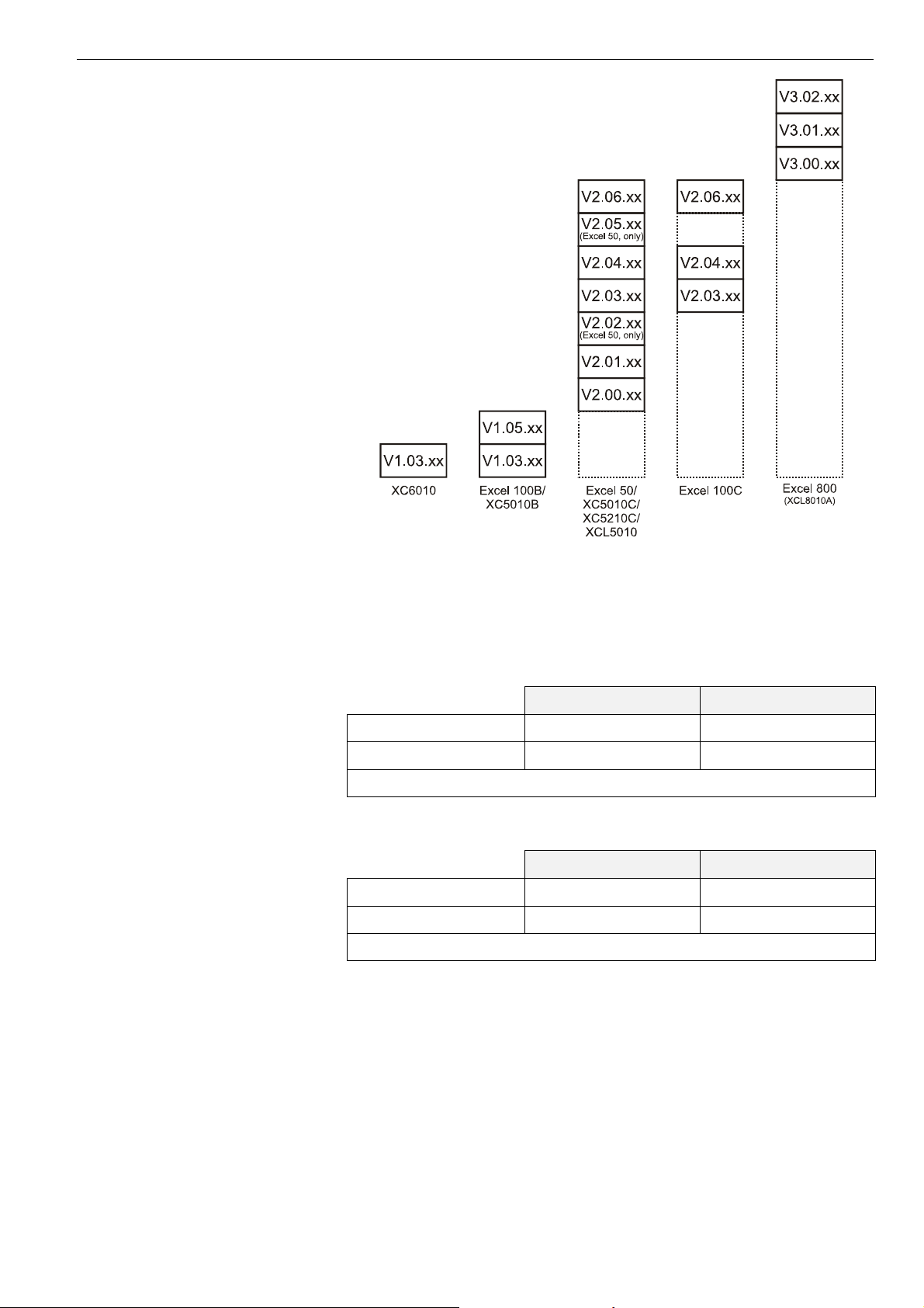
number for which they are valid. Fig. 2 shows various controllers and the firmware
version numbers that they
support.
6 EN2B-0092GE51 R0709
Page 7
Excel 50/100/500/600/800 OVERVIEW
Fig. 2. Controllers and their supported firmware versions
Excel 50 firmware compatibility Please always make sure that your firmware and the bootstrap loader match; if in
doubt, consult Software Release Bulletin(s). Special care must be taken in particular
in the case of the combinations of firmware and bootstrap loader with XD50B-xxx
modules as set forth in Table 1.
Table 1. Firmw
are / bootstrap loader compatibility with XD50B-xxx modules
firmware ≤ 2.06.07 firmware ≥ 2.06.08
bootstrap loader ≤ 1.01.07 NO* OK
bootstrap loader ≥ 1.01.08 OK OK
*Problems may occur when LONWORKS bus is in use.
Table 2. Firmware / bootstrap loader compatibility with XD50-xxx modules
firmware ≤ 2.06.07 firmware ≥ 2.06.08
bootstrap loader ≤ 1.01.07 OK OK
bootstrap loader ≥ 1.01.08 OK OK
*Problems may occur when LONWORKS bus is in use.
Datapoint description Datapoints are the basis of the Excel 50/100/500/600/800 system. Datapoints
contain system-specific information such as values, status, limit values, and default
settings. The user has easy access to datapoints and the information they contain.
The user can recall and modify information in the datapoints.
Time programs Whenever you want, you can use time programs to enter the setpoint or status for
any datapoint.
The following time programs are available:
• Daily programs
EN2B-0092GE51 R0709
7
Page 8

OVERVIEW EXCEL 50/100/500/600/800
• Weekly programs
• Annual programs
• The "TODAY" function
• Special day list
Daily programs are used to create a weekly program. The annual program is
created automatically by multiplying the weekly program and then incorporating
additional daily programs.
The "TODAY" function enables you to have a direct influence on the switching
program. This function enables you to allocate a setpoint or status to the selected
datapoints for a defined time period. This action does not depend on the current
daily program.
Alarm handling The alarm handling facility offers system security. Alarm signals can, for example,
alert the operator to maintenance work that is due. All alarms that occur are stored
in data files and reported immediately. If your system configuration allows, you can
also list alarms on a printer or transmit alarms to higher-level front-ends.
There are two kinds of alarm: Critical and Non-critical. Critical alarms have priority
over non-critical alarms. System alarms, caused by a fault in a controller, are always
critical alarms.
To distinguish between alarm types, you can generate your own alarm messages or
select appropriate messages already in the system.
The following events all generate alarm messages:
• Exceeding limit values
• Overdue maintenance work
• Totalizer readings
• Digital datapoint changes of state
Application program You can use the Honeywell CARE engineering tool to create application programs
for your system. A particular advantage offered by Honeywell CARE is the ability to
create a fully functional control program without having to be familiar with the
programming language.
CARE stands for Computer Aided Regulation Engineering.
Passwords Your control system is also protected by passwords. This ensures that only
authorized persons have access to the system data. There are four operator levels,
each protected by its own password.
• Operator level 1: Read only; the operator can display information about
setpoints, switching points, and operating hours.
• Operator level 2: Read and make limited changes; the operator can display
system information and modify certain preset values.
• Operator level 3: Read and make changes; system information can be displayed
and modified.
• Operator level 4: Programming.
Password protection prevents unauthorized access system information and ensures
permanent, secure system operation.
EN2B-0092GE51 R0709 8
Page 9
EXCEL 50/100/500/600/800
DATAPOINTS
An Excel 50/100/500/600/800 system can have the following number of datapoints:
Excel 50: 22 physical (onboard I/Os) plus up to 46 physical LON I/Os
Excel 100: 36 physical (onboard I/Os)
Excel 500: 128 physical I/Os, extendable via L
Excel 600: 128 physical I/Os
Furthermore, Excel 50/100/500/600 support an additional 256 pseudo datapoints.
Excel 800: 381 datapoints (random mix of physical and pseudo datapoints)
A datapoint has different attributes according to its type. Attributes are displayed
and modified on the XI581 (not with XCL5010, Excel 100C), XI582, and the PCbased XL-Online operator interfaces or on the Excel 50 MMI. Attributes contain
information about the given datapoint. This information could be:
• Input limits values
• Operating status
• Current temperature
• Elapsed run time
The following sections provide more-detailed information about the different kinds of
datapoints and datapoint attributes and explain which attributes are assigned to
which datapoints.
ONWORKS I/Os
Physical Datapoints
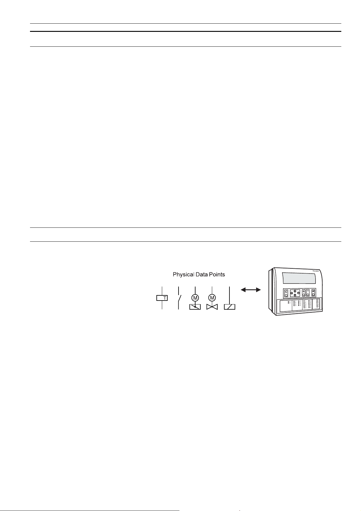
Physical datapoints are inputs and outputs attached to hardware devices like
sensors and actuators.
Fig. 3. Physical datapoint symbols
The following are examples of physical datapoints
Analog inputs NTC, PT 1000, PT 3000, BALCO Sensors (PT 3000/BALCO not with Excel 100C),
standard 0 (2)...10 V and 0 (4)...20 mA input, to connect e.g. outside air
temperature sensors.
Analog outputs Outputs with a continuous 0...10 V output signal for controlling continuous actuators
(Excel 100C supplies up to 20 mA on the analog outputs).
Digital inputs Inputs for processing voltage-free signals (switches, contacts).
Digital outputs (not Excel 100C) Outputs for driving three-position actuators, for example, a damper motor; two
position devices, for example, a circulation pump; 0...10 V and pulsed outputs
Totalizer inputs Digital inputs for processing pulsed signals up to 20 Hz (depending on Distributed
I/O module specifications), for example, metered energy consumption.
EN2B-0092GE51 R0709 9
Page 10
DATAPOINTS EXCEL 50/100/500/600/800
Flexible Datapoints
Flexible datapoints allow the control of more than one physical output with one
datapoint. There are three subordinate types of flexible datapoints:
1. Pulse 2
2. Multi-stage
3. Feedback.
Pulse 2 flexible datapoint A pulse 2 datapoint allows to pulse two digital outputs (e.g. relays). When activated
(e.g. set to “on”), Pulse 2 triggers one of the digital outputs, and when deactivated,
Pulse 2 triggers the other digital output.
Pulse 2 “on” Pulse 2 “off”
Relay 1
Relay 2
Fig. 4. Pulse 2 flexible datapoint switching
Multistage flexible datapoint Multistage flexible datapoints allow to switch up to six physical digital outputs via
one datapoint. A typical example would be a multi-stage electric heater or a multistage fan.
A multistage flexible datapoint provides up to six editable stage texts, e.g., stage 1,
stage 2, stage 3, etc, to be edited in CARE.
Feedback flexible datapoint Feedback flexible datapoints, also called “DO feedback DI” combine up to three
pairs of digital outputs/digital inputs to form up to three-stage switching with
feedback. The digital inputs of each pair act as the feedback point.
If the digital input does not feedback the actual equipment status within a predefined
time “Off Phase”, then the software will switch down this point type until a "nonalarm" state is reached. In extreme cases, the point may be switched to the off
position. See also “Off Phase”.
Increased support (V2.04.xx or higher) Excel 500 controllers now support up to 60 flexible datapoints. In case of Feedback
flexible points, the maximum number is 128.
Previous firmware versions supported only up to 20 flexible datapoints.
Pseudo Datapoints
Excel 50/100/500/600 support 256 pseudo datapoints, while Excel 800 supports 381
datapoints (consisting of a random mix of physical and pseudo datapoints)
Pseudo datapoints are values (intermediate results and parameters) computed
while the application program is running. In contrast to physical datapoints, pseudo
datapoints are not directly connected to hardware devices.
EN2B-0092GE51 R0709 10
Page 11

EXCEL 50/100/500/600/800 DATA POINTS
Access via the user address During system operation, you may need to access these values. To simplify this
process, you can include pseudo datapoints in the datapoint list, where you can
access them directly via their user addresses.
Like physical datapoints, pseudo datapoints, too, can have different attributes; for
example, they can specify a manual value, set minimum and maximum values, or
log trends.
The following are types of pseudo datapoints:
• Pseudo analog points
• Pseudo digital points
• Pseudo totalizer inputs
• Pseudo point multistage
Pseudo analog points Pseudo analog points are software points containing an analog value in the user
program.
A pseudo analog point could, for example, contain a flow temperature setpoint calculated from the room setpoint and the outside air temperature via the heating
curve.
Pseudo digital points Pseudo digital points are software points containing a digital value in the user
program.
For example, logical AND operation.
The AND operation provides a logical 1 output when all input conditions are also
logical 1. Otherwise the output is a logical 0. If the user program contains such an
AND operation on different input conditions, then the output could be available as a
pseudo digital datapoint.
Pseudo totalizer inputs Pseudo totalizer inputs are digital software points from the user program, where a
totalizer counter input is recorded.
Pseudo point multistage Pseudo point multistage datapoints are identical to flexible datapoint of the type
"multistage" except that they allow for 16 stages (including the “off stage“) and the
attribute "Status Text" allows for 16 status texts to be attached. The attribute "Technical Address" is not required.
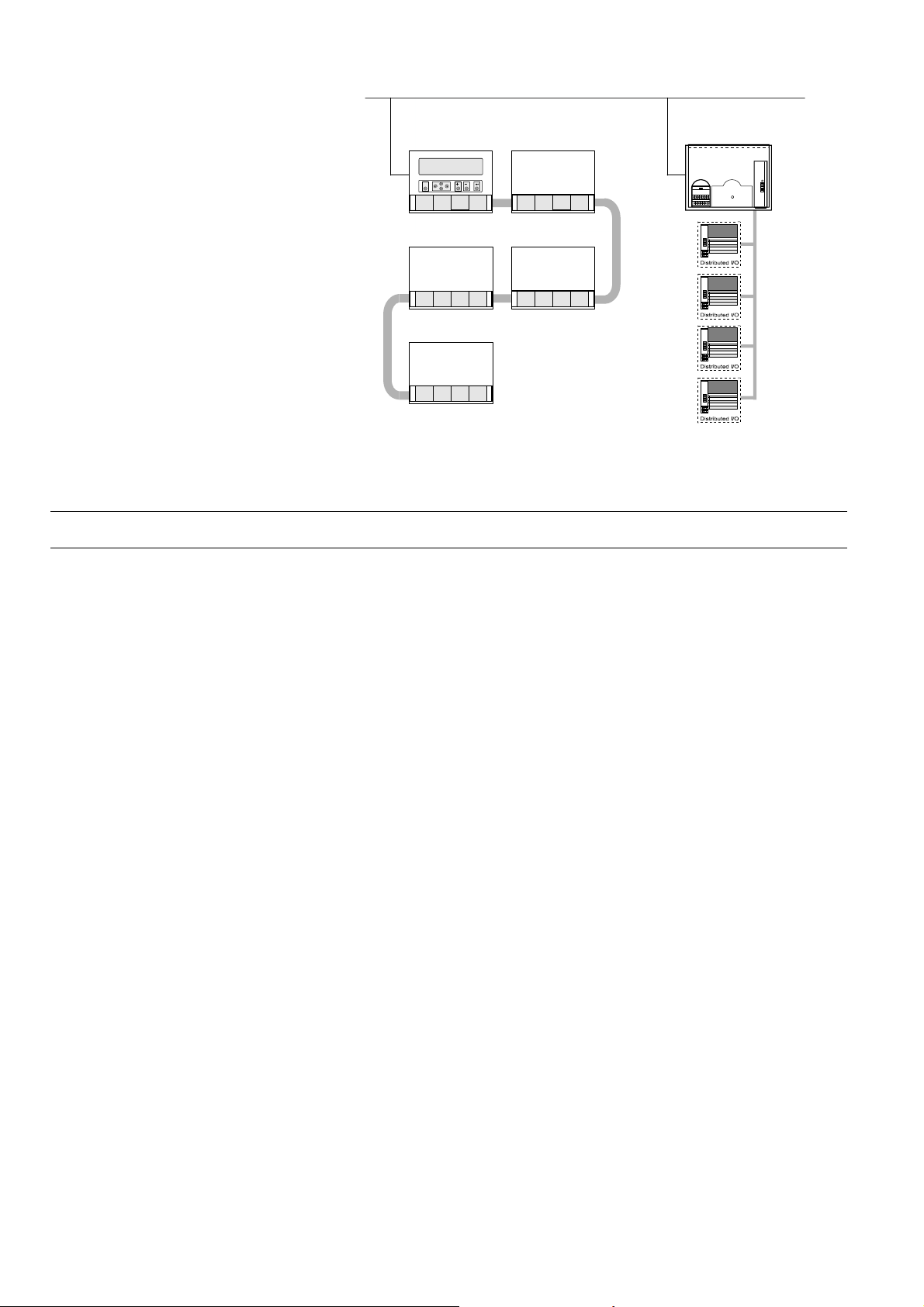
Global Datapoints
If your control and monitoring system contains more than one controller, the controllers communicate with one another via the system bus. Any given controller can
thus both receive (read) datapoints from other controllers and transmit datapoints to
other controllers. Such datapoints are referred to as global datapoints.
NOTE: The term “global” as used here encompasses more than just those points
explicitly labeled as “global” in the CARE engineering tool.
Global datapoints which a controller receives (reads) from other controllers are
referred to as local global datapoints, and global datapoints which a controller
transmits to other controllers are referred to as remote global datapoints.
During CARE engineering, the program engineer must take care that he does not
exceed the maximum allowed 256 global datapoints (remote and local) per
controller.
EN2B-0092GE51 R0709
11
Page 12
DATAPOINTS EXCEL 50/100/500/600/800
SYS
S
TEM BU
C
LON
Fig. 5. Global datapoints are available to all controllers on the system bus
Mapped Datapoints (V2.04.xx or higher)
With firmware version V2.04.xx or higher, those Excel 50/500 controllers which
feature free programmability on L
chip, i.e. date code 0044 or higher) may have I/O devices connected via the
L
ONWORKS network. LONWORKS network variables (or individual fields of structured
network variables) can be mapped to the attribute "Value" of physical datapoints
(AI/DI/AO/DO). Pseudo analog, pseudo digital, and pseudo multistage points are
also supported for NV mapping.
See Excel 50/500 L
for more information on L
ONWORKS (those that contain the 3120E5 Neuron
ONWORKS Mechanisms Interface Description, EN0B-0270GE51,
ONWORKS network variables and datapoint mapping.
EN2B-0092GE51 R0709 12
Page 13
EXCEL 50/100/500/600/800
ATTRIBUTES
Each datapoint type has associated with it various parameters which allow the user
to set, e.g., the user address, the level of access protection, alarm behavior, and
other options. These parameters are called attributes. Each attribute performs a
specific function related to the datapoint.
A complete list of datapoint types and their attributes appears in Table 17 through
Table 19. Not all attributes are available for every
Point refreshing (V1.5.x) Four attributes ("Value", "Manual Value", "Operating Mode", and "Alarm Status") will
be simultaneously refreshed to an XL-Online operator interface.
NOTE: A complete list of attributes associated with the various datapoint types can
be found in the section "List of Datapoint Attributes" on page 39.
Access Level
Four levels of protection The attribute "Access Level" protects datapoints against unauthorized changes on
the basis of the password level needed to modify a datapoint.
"Access Level" attributes between "1" and "4" are assigned to a point. These
attributes correspond to the four password levels found in the XI581 (not with
XCL5010, Excel 100C), XI582, and XL-Online operator interfaces and the Excel 50
MMI:
• Operator level 1: Read only.
• Operator level 2: Read and make limited changes.
• Operator level 3: Read and make changes.
• Operator level 4: Programming.
For example, setting the "Access Level" attribute for the datapoint with the user
address "room temp floor 1" to "2" means that all attributes for this datapoint can
now only be edited or modified at password level 2 or higher.
datapoint type.
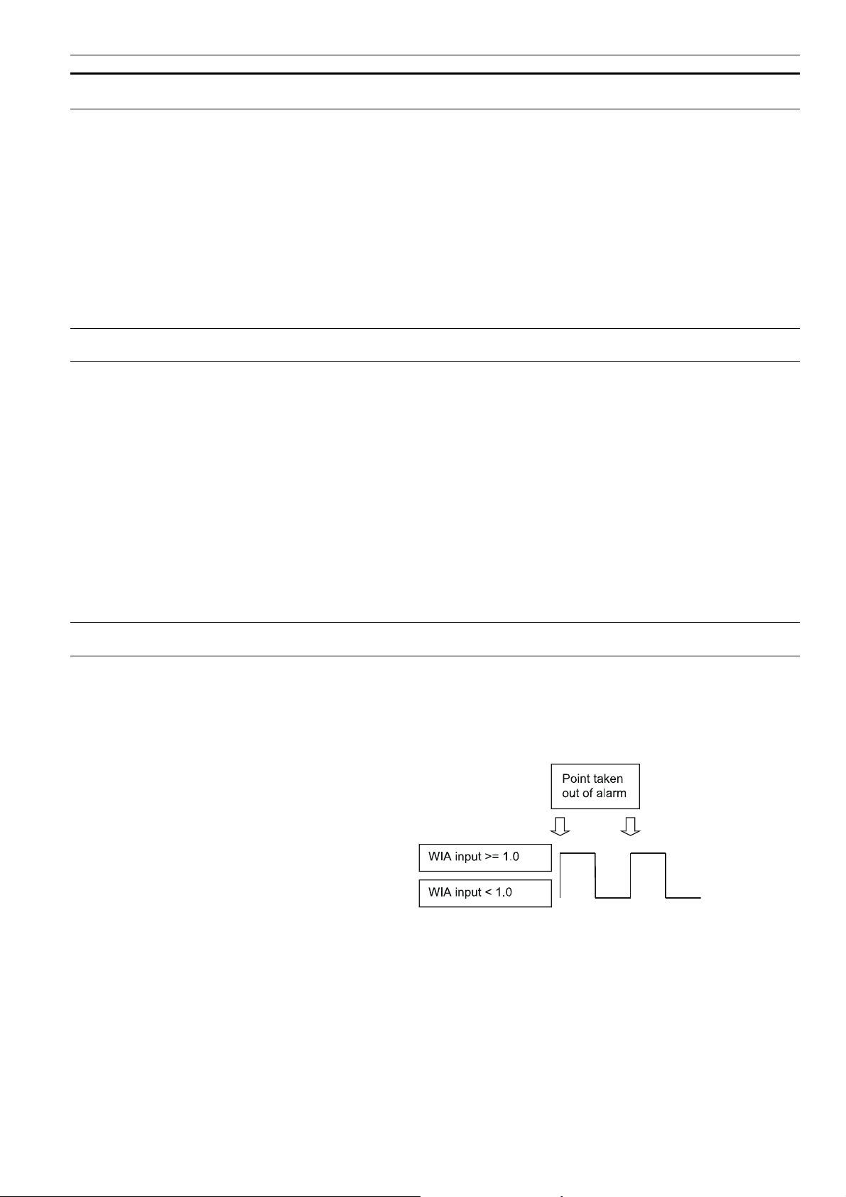
Acknowledge Alarm (V2.04.xx or higher)
The attribute "Acknowledge Alarm" allows a controller to acknowledge an alarm for
a flexible datapoint of the type "feedback" without changing the operating mode. The
controller takes the point out of alarm as soon as a rising edge is detected on the
input of the WIA statement writing to the attribute "Acknowledge Alarm".
Fig. 6. The "Acknowledge Alarm" attribute for WIA statement
This attribute is a virtual attribute and can be accessed only by a WIA statement in
CARE. It is not part of the datapoint description and therefore cannot be displayed
on an MMI or building supervisor.
EN2B-0092GE51 R0709 13
Page 14

ATTRIBUTES EXCEL 50/100/500/600/800
Active State (prior to V2.04.x)
The attribute "Active State" defines when a digital input/output is active.
NOTE: The "Active State" attribute does not reflect the current condition of a digital
datapoint.
NOTE: This is not applicable to digital inputs in applications designed for con-
trollers using V2.04.xx firmware or higher. In such applications, this
attribute is fixed at 1, and the new attribute "Normally Open/Normally
Closed" (NO/NC) is active (see section "Normally Open/Normally Closed
(V2.04.xx or higher)" on page 28 for more details).
T
he following values are possible:
• 0 = digital input/output is active when a "logical 0 signal" is present
• 1 = digital input/output is active when a "logical 1 signal" is present
Table 3 indicates the active state for various conditions of the XF523 and XFL523
modules.
Table 3. Active state for the digital input of XF523 and XFL523 modules
digital input
contact status open closed
CARE definition (NC/NO system
diagram)
definition - in XL-Online DP-Editor
attribute "Active State"
(change Active/Passive State text)
CARE interpretation (control table) 1 1 0 0 0 0 1 1
display at operator interface
(status text)
trouble:
NC NO NC NO
1 0 1 0 1 0 1 0
OFF/
alarm
ON/
operating
RTN*
* RTN = Return To Normal
NOTE: XFL523 Module is applicable only for V2.0.xx software.
OFF/
trouble:
alarm
ON/
operating
RTN*
ON/
operating
RTN*
OFF/
trouble:
alarm
ON/
operating
RTN*
OFF/
trouble:
alarm
Active State (Excel 800)
The attribute "Active State" defines when a digital input/output is active.
1 means, that a digital input/output is active when a "logical 1 signal" is present
NOTE: "Active State" = 0 is not allowed/possible.
NOTE: The "Active State" attribute does not reflect the current condition of a digital
datapoint.
EN2B-0092GE51 R0709 14
Page 15

EXCEL 50/100/500/600/800 ATTRIBUTES
Table 4. Active State for the digital input of XF823 and XFL823 modules
digital input
contact status open closed
CARE definition (NC/NO system
diagram)
definition - in XL-Online DP-Editor
attribute "Active State"
(change Active/Passive State text)
CARE interpretation (control table) 1 0 0 1
display at operator interface
(status text)
trouble:
NC NO NC NO
1 1 1 1
OFF/
alarm
* RTN = Return To Normal
OFF/
trouble:
alarm
ON/
operating
RTN*
ON/
operating
RTN*
Alarm Delay
Delaying alarm outputs The alarm delay time (in seconds) is entered in the attribute "Alarm Delay". The
alarm delay time determines how long an alarm condition must exist before an
alarm is generated. Entering an alarm delay time of 10 seconds means that the limit
value must be exceeded for at least 10 seconds before this datapoint generates an
alarm. If the limit value lasts for only 7 second, then no alarm occurs.
Alarm Suppression
The attribute “Suppress Alarm” establishes whether or not alarm messages from the
following alarm attributes should be suppressed:
• Operational status
• Min/Max. limit
• Maintenance alarm
• Interval counter
• Alarm Status
The following entries are possible:
• Off = Alarms not suppressed
• On = Alarms suppressed
Example: digital input In addition to a variety of other attributes, a digital input also has the "Operating
Mode", "Alarm Status", and "Maintenance Alarm" attributes. If alarm suppression is
activated for this datapoint, then no message is displayed during an operating mode
change-over, or when changing into the alarm condition, or when reaching the
maintenance alarm.
Suppression of system The controller will not issue a system alarm when the alarm’s system alarm text
alarms (V2.04.xx or higher) starts with an @ character.
Alarm Status (prior to V2.04.x)
Alarm monitoring In the case of a digital input or a pseudo digital point, the attribute "Alarm Status"
specifies whether or not alarm monitoring is required.
The following entries are possible:
• Yes Alarm monitoring is required
• No Alarm monitoring is not required
EN2B-0092GE51 R0709
15
Page 16
ATTRIBUTES EXCEL 50/100/500/600/800
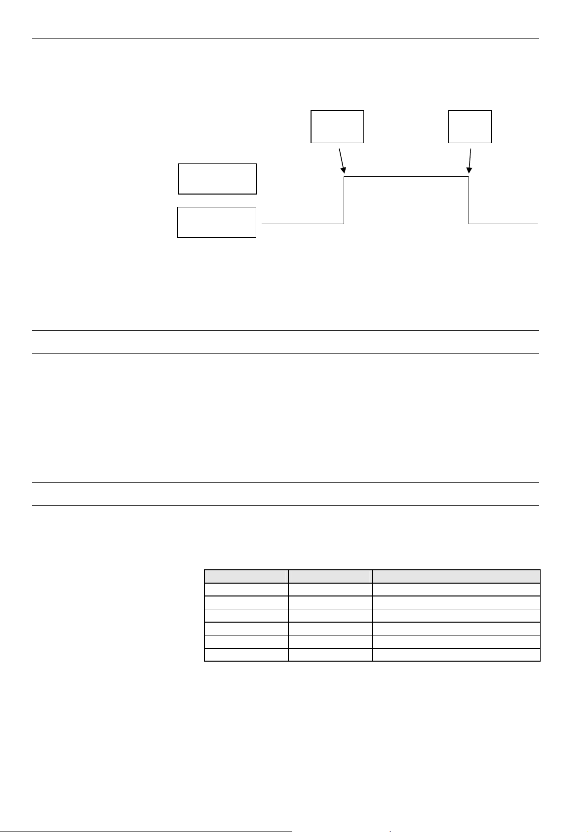
When alarm monitoring is required, the alarm message occurs when the digital point
changes from the active state to the passive state (alarm reached). An additional
message is generated (alarm going) when the digital point returns to the active state
(see Fig. 7).
Alarm
reached
Alarm
ending
DI in
“Active State”
DI in
“Passive State”
Fig. 7. Alarm status messaging
NOTE: The active state and passive state are defined in the "Active State"
datapoint attribute.
Alarm Status (V2.04.xx or higher)
Alarm monitoring In the case of a digital input or a pseudo digital point, the attribute "Alarm Status"
specifies whether or not alarm monitoring is required.
The following entries are possible:
• Yes Alarm monitoring is required
• No Alarm monitoring is not required
When alarm monitoring is required, the alarm message occurs depending on the
physical contact status and on the logical status as defined in the online attribute
“Normally Open/Normally Closed”.
Alarm Type
The attributes listed in Table 5 are capable not only of generating alarms, but also of
writing them to the internal alarm memory and sending them to the PC front-end or
to the modem module (when connected).
Table 5. Alarm attributes
attribute always critical optional critical or non-critical
Operating Mode X
Min. Limit X
Max. Limit X
Maintenance Alarm X
Interval Counter X
Alarm Status X
Changing over the attribute "Operating Mode" always results in a critical alarm, but
the attribute "Alarm Type" offers a choice for the alarm attributes "Min. Limit", "Max.
Limit", "Maintenance Alarm", "Totalizer", and "Alarm Status" whether an alarm is
classified as critical or non-critical.
EN2B-0092GE51 R0709 16
Page 17
EXCEL 50/100/500/600/800 ATTRIBUTES
Distinguishing between critical and non-critical alarms is significant for the subsequent reporting of the alarms to the PC front-end or to the modem module. Compared to non-critical alarms, critical alarms are given priority on the bus when
several alarms are in the alarm queue.
When the type of alarm for a datapoint has been decided, e.g. "critical" alarm type, it
refers to all alarm attributes for this datapoint.
Alarm Definition
In the datapoint description, the alarms can be influenced using the functions
described below (see also Table 6 on page 18).
A
Alarm delay An alarm signal can be delayed by entering an alarm delay time. An alarm signal will
Suppress alarm If an alarm signal is not desired from a particular datapoint, this can be fixed in the
larm type For each datapoint in the datapoint description, the user can determine whether the
signals generated are to be treated as critical or non-critical alarm.
be generated only if an alarm continues uninterrupted during the alarm delay time.
datapoint description. Thus, all the alarm signals relevant to the particular datapoint
and the "Operating Mode" alarm types are suppressed.
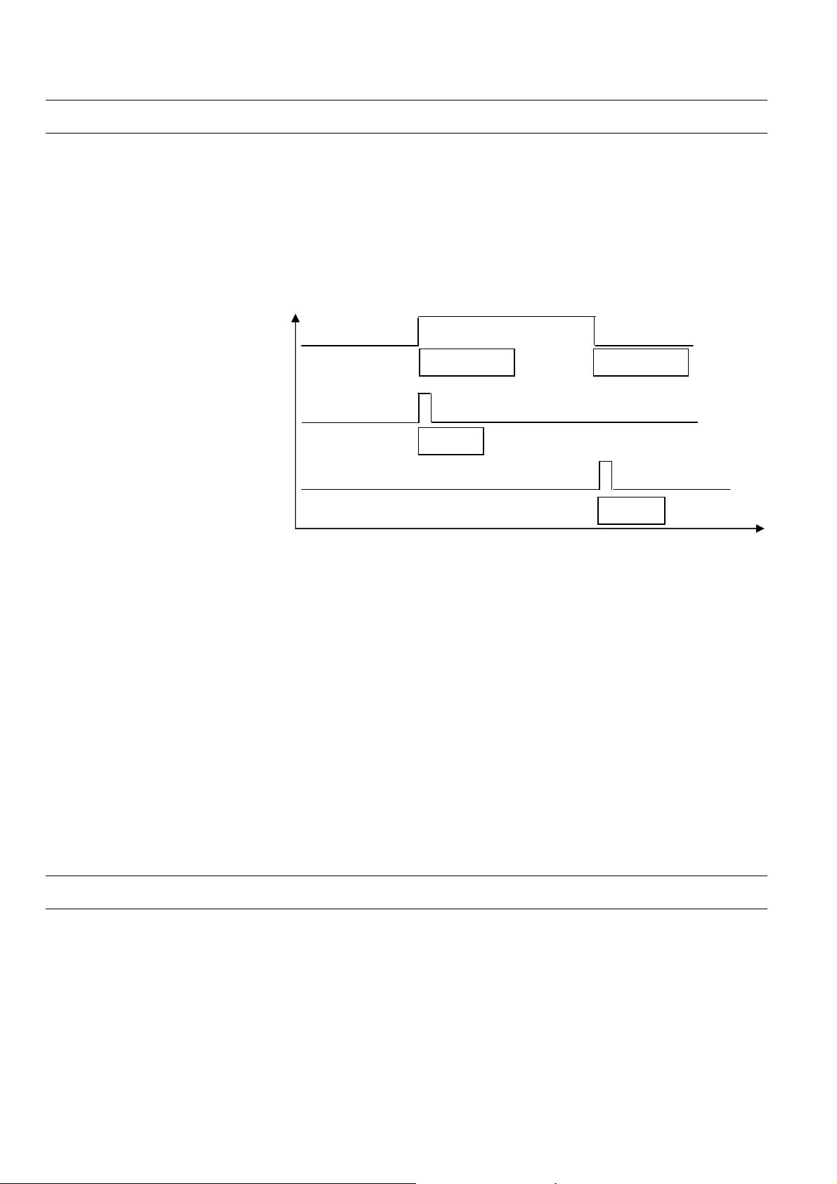
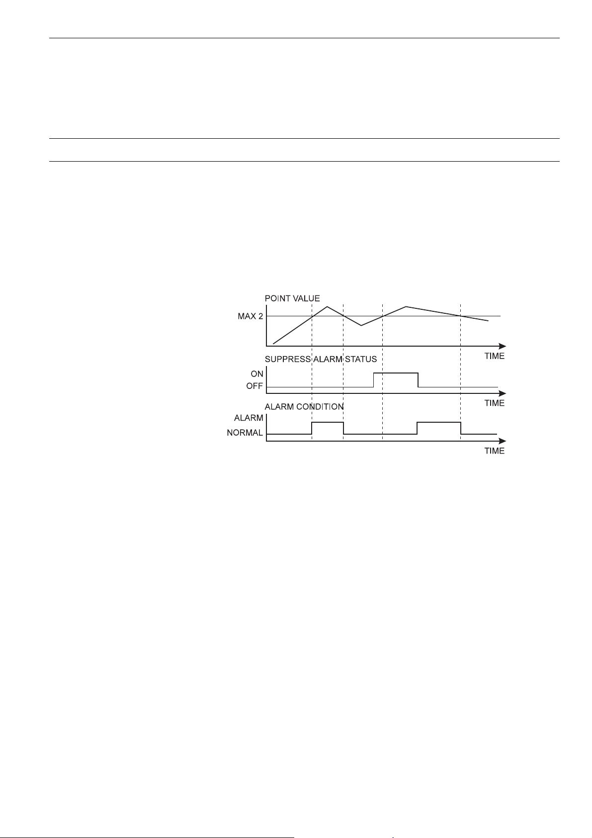
Fig. 8. Alarm condition depending on point value and Suppress Alarm status
Fig. 8 shows an example of a changing point value that rises above and falls below
the limit Max 2. If Suppress Alarm is not active, then the alarm condition switches
between normal to alarm, according to the limit Max 2. If Suppress Alarm is active,
then the alarm condition remains normal unless Suppress Alarm is switched off
before the point value falls below the limit Max 2. Regardless of the setting of the
Alarm suppression flag, an alarm is entered into the controller's history buffer and is
also available in the EBI alarm report.
Point alarm It is possible to view all datapoints at the operator interfaces for which the limit value
(analog point) or the alarm status (digital point) is currently exceeded.
Driven by a menu, the user address and the accompanying alarm text are displayed
on the XI581 (not with XCL5010, Excel 100C) or XI582 operator interfaces or Excel
50 MMI.
On the XL-Online operator interface, a datapoint within the framework of the
datapoint description can be seen in all four password levels. If a current alarm is
present for the point in question, the attribute “Point in Alarm” produces the display
“Yes”, otherwise “No”.
Within the framework of the datapoint description, it is possible, under the attribute
“Alarm text”, to enter an alarm text of up to 18 characters in addition to the preprogrammed text. There are 256 alarm texts in total.
Table 6 presents a summary of various alarm types and attributes.
EN2B-0092GE51 R0709
17
Page 18
ATTRIBUTES EXCEL 50/100/500/600/800
Table 6. Alarm summary
alarm type/attributes alarm status
Limit Values selection in DPD* possible possible X 8 possible
Alarm Status selection in DPD* possible possible X 2 possible
Maintenance Alarm selection in DPD* - possible - 1 -
Totalizer selection in DPD* - possible - 1 -
Operating Mode always critical - possible - 2 -
System Alarms always critical - - - approx. 110 -
user program reports always non-critical - - - - -
*DPD = datapoint description
enter alarm
delay time
NOTE: A point is still seen as “in alarm” even when alarm suppression is enabled.
alarm
suppression
point in
alarm
no. of prepro-
grammed texts
supplementary
text
Cycle Count
The attribute "Cycle Count" contains the value indicating the number of transitions
to the active state (see "Active State (prior to V2.04.x)" on page 14).
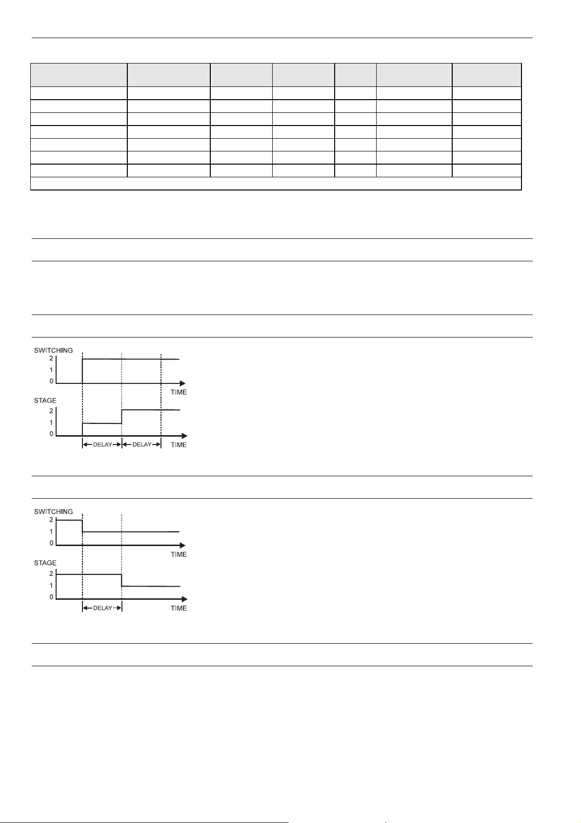
Delay Time Switching Up
Fig. 9. Delay time switching up
Delay Time Switching Down
Fig. 10. Delay time switching down
This attribute is used in conjunction with flexible points of
the type "feedback". It defines the delay time between
switching upwards from one stage to another. The delay
time affects every stage. The delay time also takes effect
when switching, e.g. from manual value 0 to 2. In this case,
it is switched from stage 0 to stage 1, then to stage 2 with
the delay time between the switching processes.
• Range: 0 to 255s
• Default value : 10s
• Resolution: 1s
This attribute is used in conjunction with flexible points of
the type "feedback". It defines the delay time between
switching downwards from one stage to another. The delay
time affects every stage.
• Range: 0 to 255s
• Default value: 10s
• Resolution: 1s
The feedback delay time starts to count after termination of
delay time switching up/delay time switching down.
Descriptors
Informative descriptors A controller contains up to 128 physical datapoints and up to 256 pseudo
datapoints. The Excel 100C provides 36 physical datapoints. An individual user
address can be assigned to each of these 384 datapoints.
EN2B-0092GE51 R0709 18
Page 19

EXCEL 50/100/500/600/800 ATTRIBUTES
255 plain-language descriptors can be created with a maximum of 32 characters
each. These descriptors are then assigned to datapoints in the datapoint description
via the attribute "Descriptor".
Descriptors complete the information concealed behind the user address. They can
contain, for instance, a reference to a section of a building.
The following list is an example of the relationship between user addresses and
descriptors:
User Address Descriptor
Room temp floor 1 Heating circuit, West wing
Room temp floor 3 Heating circuit, West wing
Room temp floor 10 Heating circuit, East
Room temp corridor Heating circuit, East
Flow temp floor 1 Heating circuit, West wing
Lights floor 1 Building section V
Lights corridor Building section V
Engineering Unit
The attribute "Engineering Unit" contains a list for selecting different engineering
units for both analog datapoints (physical and pseudo), totalizer inputs (physical and
pseudo), and digital datapoints.
If, for instance, the external temperature is measured by an analog datapoint, the
engineering unit of this datapoint must be set to "°C" or "°F". If the electrical load is
detected by a totalizer input, the engineering unit must be set to "kWh" for kilowatthours.
Feedback Delay
The attribute "Feedback Delay" determines the time delay between, e.g. when a
pump switched on (and detected) and when this status is made available to a
program.
High/Low Alarm/Warning Limits
Specifying limit values In the case of analog inputs (e.g. inputs for sensing room temperature) and pseudo
analog points (for instance, internally computed datapoints for the heating flow
setpoint), two minimum and two maximum monitored limit values may be entered.
The following four limit value attributes exist:
• Low Warning Limit
• Low Alarm Limit
• High Warning Limit
• High Alarm Limit
Exceeding the limit values generates an alarm.
Example: Monitoring supply air temperature limits (see Fig. 11).
EN2B-0092GE51 R0709
19
Page 20

ATTRIBUTES EXCEL 50/100/500/600/800
Fig. 11. Monitoring supply air temperature limits
Hours Run
Display of elapsed hours The attribute "Hours Run" returns the total number of hours during which any of the
stages is in the ON position. However, if more than one stage is in the ON position,
the "Hours Run" count is not added up, but rather counted only once.
Display of the elapsed hours run with activated hours run logging (see also "Hours
Run Log" on page 20).
NOTE:
If the attribute "Active State" of the point is 0, then the OFF position is also
counted.
Hours Run Log
Hours run log An hours run log can be carried out for digital datapoints (physical and pseudo) and
for flexible datapoints, e.g. logging the hours run by a heating circuit pump. This
requires the decision: hours run log = Yes/No to be made in the attribute "Hours
Run Log". The accumulated hours run are displayed in the attribute “Hours Run”.
Hours run are logged with a sample rate of 1 minute.
Hours Since Serviced
Display hours run since last maintenance The elapsed hours run since the last maintenance work are totaled in the attribute
"Last Maintained". If, for example, the maintenance alarm is 500 hours, and a pump
has already been running for 120 hours, then the entry in the attribute “Last
maintained” will be 120 hours. By comparing the attributes "Maintenance Alarm" and
"Last Maintained", the user can see that the next maintenance period will be after
an additional 380 hours have elapsed.
If the maintenance alarm is reached, and the maintenance work has been performed, the counter can be reset manually. The counter can also be reset manually
before reaching the maintenance alarm if, for instance, the maintenance has been
performed earlier.
EN2B-0092GE51 R0709 20
Page 21

EXCEL 50/100/500/600/800 ATTRIBUTES
If the counter is not reset, on expiration of the maintenance alarm, e.g. after 500
hours, the elapsed hours run continues to be incremented, and an additional alarm
will be generated when 1000 hours running has been reached.
Hysteresis
The following hysteresis attributes allow the user to control the triggering conditions
based on a changing parameter under which actions are taken, such as alarm
signaling, writing values to buffers, etc. A hysteresis can be used, e.g., to prevent an
alarm from being generated unless the value being monitored changes by more
than a given value. This eliminates unnecessary alarm generation and reduces bus
communication traffic.
Alarm Hysteresis
Alarm hysteresis (V1.5.x) In the case of analog inputs and pseudo analog points, the attribute "Alarm
Hysteresis" is available. It provides variable hysteresis that can be implemented,
e.g., in order to reduce the cost of communicating with a remote front-end.
The hysteresis value is set from an MMI and can have a value anywhere in the
range defined by [10
set in the attribute "Engineering Unit". The minimum value for the hysteresis is 10
Alarms are generated under the following conditions:
• Max 1 Alarm (generated if MAX 1 is exceeded)
• Max 2 Alarm (generated if MAX 2 is exceeded)
• Max 2 Normal (generated if the value falls below MAX 2-Hysteresis)
• Max 1 Normal (generated if the value falls below MAX 1-Hysteresis)
• Min 1 Alarm (generated if the value falls below MIN 1)
• Min 2 Alarm (generated if the value falls below MIN 2)
• Min 2 Normal (generated if the value MIN 2+Hysteresis is exceeded)
• Min 1 Normal (generated if the value MIN 1+Hysteresis is exceeded)
The CARE default value (i.e. 1% of actual value and no less than 0.2) for this
attribute is 0. Access to "Alarm Hysteresis" is also possible via RIA/WIA.
NOTE: The number of decimal places can be changed only using CARE.
NOTE: Attempting to enter a hysteresis value that is less than the allowed
minimum will result in the attribute being assigned the minimum value as
defined above.
Example:
In this example, the number of decimal places in the attribute "Engineering Unit" has
been chosen to have a value of 2. Fig. 12 shows an example datapoint value as a
function of time that increases and decreases over the range from Max 1 to Min 1.
-a
to (Max1 - Min1)] where “a” is the number of decimal places
-a
.
Fig. 12. Example of alarm hysteresis
The “normal” and “alarm” states as defined by the attribute "Alarm Hysteresis" are
the determined using the appropriate values in the formula given above:
EN2B-0092GE51 R0709
21
Page 22

ATTRIBUTES EXCEL 50/100/500/600/800
Range = [10-2 to (Max1 -Min1)] = [0.01 to 2]
Table 7 lists the resulting alarm conditions for the chosen hy
Table 7. Alarm conditions for alarm hysteresis
limit normal to alarm condition alarm to normal condition
Max 1 4.00 4.00 - 0.05 = 3.95
Max 2 5.00 5.00 - 0.05 = 4.95
Min 1 2.00 2.00 + 0.05 = 2.05
Min 2 0.5 0.5 + 0.05 = 0.55
steresis value of 0.05:
Trend Hysteresis
Trend hysteresis (V1.5.x) The attribute "Trend Hysteresis" is available for the trend functions “Local Trend
Data” and “Trend Setup Data”. The attribute "Trend Hysteresis" prevents new
values from being written to the trend buffer unless the datapoint value changes
(positively or negatively) at more than the specified trend hysteresis. The minimum
hysteresis value is 10
"Engineering Unit"). The CARE default value (i.e. 1% of actual value and no less
than 0.2) for this attribute is 0. Access to "Trend Hysteresis" is also possible via
RIA/WIA.
This value can be edited from an operator interface (XI581 (not with XCL5010,
Excel 100C), XI582, XL-Online, or Excel 50 MMI) via the B port (XC5010C/XC6010)
or the serial port, the system bus (XBS 1.3.3 and higher and XFI 1.6.1 and higher)
and CARE RIA/WIA statements. The password level for this attribute is determined
by the attribute "Access" (default initialization value in CARE is 0).
-a
(a = number of decimal places set in the attribute
Fig. 13. Example of the attribute "Trend Hysteresis"
Broadcast Hysteresis
Broadcast hysteresis (V1.5.x) The attribute "Broadcast Hysteresis" is available for the datapoint type "Global
Analog". The attribute "Broadcast Hysteresis" prevents new values from being
broadcast to other controllers unless the datapoint value changes (positively or
negatively) at least by the amount specified in the attribute "Broadcast Hysteresis".
The minimum hysteresis value is 10
attribute "Engineering Unit"), but not smaller than 0.2 (see also the example in
section "Value Hysteresis" on page 36). The CARE default value (i.e. 1% of actual
value and no less than 0.2) for this attribute is 0. Access to the attribute "Alarm
Hy
steresis" is also possible via RIA/WIA.
This value can be edited from an operator interface (XI581 [not with XCL5010,
Excel 100C], XI582, XL-Online, and Excel 50 MMI) via the B port (XC5010C /
EN2B-0092GE51 R0709 22
-a
(a = number of decimal places set in the
Page 23

EXCEL 50/100/500/600/800 ATTRIBUTES
XC6010) or the serial port (Excel 100C, Excel 500), the system bus (XBS 1.3.3 and
higher and XFI 1.6.1 and higher), and CARE RIA/WIA statements. The password
level for this attribute is determined by the "Access" attribute (default initialization
value in CARE is 0). If several global points (remote points) are assigned to the
same physical point, the lowest global point "Broadcast Hysteresis" value of all
assigned global points is used.
Intrinsic Hysteresis for Analog Input Signals
A minimum default hysteresis of 37 mV (24 - 1 bit) for 0 to 10 V input signals is
implemented. Due to the nonlinearity of NTC sensors, the hysteresis varies over the
temperature range, whereas it is approximately constant for PT 100/1000/3000 and
Balco 500 sensors. Approximations of hysteresis depending on the sensor and
temperature range are summarized below.
NOTE The Intrinsic Hysteresis for analog input signals is not a user-
programmable attribute, but rather an intrinsic hysteresis of the Excel
50/100/500/600/800.
NTC 20k Ω Hysteresis varies nonlinearly over the entire temperature range and depending on
whether the upper boundary (MAX LIMIT) or the lower boundary (MIN LIMIT) is
exceeded. The approximations shown in Table 8 can be used in practice
(intermediate values can be interpolated):
T
able 8. Intrinsic hysteresis values for various temperature ranges
temperature range
-40 °C (-40 °F) 2.2 K (4.0 °F) 2.5 K (4.5 °F)
-30 °C (-22 °F) 1.3 K (2.3 °F) 1.3 K (2.3 °F)
0 °C (32 °F) 0.4 K (0.7 °F) 0.4 K (0.7 °F)
40 °C(104 °F) 0.5 K (0.9 °F) 0.4 K (0.7 °F)
80 °C (40 °F) 1.5 K (2.7 °F) 1.5 K (2.7 °F)
100 °C (212 °F) 3.0 K (5.4 °F) 2.7 K (4.9 °F)
130 °C (266 °F) 8.5 K (15.3 °F) 7.2 K (13.0 °F)
average hysteresis
MIN LIMIT
average hysteresis
MAX LIMIT
PT 100 (not with Excel 100C) Hysteresis increases approx. linearly with temperature.
Average hysteresis: 0.75 K (1.35 °F)
Hyst. At -45 °C (-49 °F): 0.7 K (1.3 °F)
Hyst. At 145 °C (293 °F): 0.8 K (1.4 °F)
PT 1000/1 Hysteresis increases approx. linearly with temperature.
Average hysteresis: 0.8 K (1.4 °F)
Hyst. At -45 °C (-49 °F): 0.7 K (1.3 °F)
Hyst. At 145 °C (293 °F): 0.9 K (1.6 °F)
PT 1000/2 Hysteresis increases approx. linearly with temperature.
Average hysteresis: 1.6 K (2.9 °F)
Hyst. At 0 °C (32 °F): 1.3 K (2.3 °F)
Hyst. At 400 °C (752 °F): 2.0 K (3.6 °F)
PT 3000 (not with Excel 100C) Hysteresis increases approx. linearly with temperature.
Average hysteresis: 0.8 K (1.4 °F)
Hyst. At -45 °C (-49 °F): 0.7 K (1.3 °F)
Hyst. At 145 °C (293 °F): 1.0 K (1.8 °F)
Balco 500 (not with Excel 100C) Hysteresis decreases approx. linearly with temperature.
Average hysteresis: 0.9 K (1.6 °F)
Hyst. At -50 °C (-49 °F): 1.0 K (1.8 °F)
Hyst. At 150 °C (293 °F): 0.7 K (1.3 °F)
EN2B-0092GE51 R0709
23
Page 24

ATTRIBUTES EXCEL 50/100/500/600/800
Input/Output Status Text (prior to V2.04.xx)
2 status texts per digital data output Two status texts can be assigned to each digital datapoint status. Status texts give
an overview of the condition of the sensor or switching device connected to the
datapoint.
The associated status text appears in the attribute "Value" depending on the actual
point status.
For instance, the status texts could be as follows for a point connected to a digital
output:
Digital point status 0: Status Text: "Passive”
Digital point status 1: Status Text: "Active”
Table 9. Relationships between I/O Status, Active State, and Status Text
Input/Output Status Active State (prior to V.2.04.x) Status Text
0 0 active
0 1 passive
1 0 passive
1 1 active
Status Text with flexible datapoints The attribute "Status Text" allows you to describe the value sent to the controller by
the digital output Pulse 1 and by flexible datapoints. In the case of flexible
datapoints of the type "feedback", the status text refers to the value of the feedback
flexible datapoint and not to the required value.
Input/Output Status Text (V2.04.xx or higher)
With firmware 2.04.xx or higher, the relationship between physical output status and
logical output status as defined by the attribute "Normally Open/Normally Closed"
determines the display of the equivalent status text. See section "Normally
Open/Normally
Closed (V2.04.xx or higher)" on page 28 for details.
Interval Count
Interval count The attribute "Interval Count" shows the totalizer value (pulse x scaling factor)
accumulated since the last reset.
Displaying the interval count The attribute "Interval Count" can be viewed on the XI581, XI582, and Excel 50 MMI
operating units as well as via the XL-Online Operating Software and building
Supervisor front-ends like XBS, EBI and XFI. Based on mathematical rounding, it is
possible that not every value is displayed when high frequency values with high
scaling factors are received.
Resetting the interval count Resetting takes place either manually via an operating unit, by reaching the “Interval
Limit” value, or by reaching the “totalized” constant, which is 2 to the power of 31.
Totalizer overflow When the “Interval Limit” or the “totalized” constant is reached, a “Totalizer
Overflow” system alarm is created.
Interval Limit
The attribute “Interval Limit” is that value of the "Interval Count" attribute which,
when reached, will generate a “Totalizer Overflow” alarm. The highest possible
value for the attribute "Interval Count" is 99,999,999.
EN2B-0092GE51 R0709 24
Page 25

EXCEL 50/100/500/600/800 ATTRIBUTES
Electrical energy example A message should be generated after the “consumption” of 5 MWh of electrical
power. The input in the attribute “Interval Limit” must therefore be 5 MWh.
Once the interval count reaches its reporting level of 5 MWh, then a report is
generated, the interval count is reset to “Zero”, and a new totalizing period is
started.
I/O Characteristic
The attribute "I/O Characteristic" enables the user to display special input and output characteristics (see Fig. 14) for analog inputs/outputs. Special characteristics
permit, for instance, the adaptation of Excel 50/100/500/600/800 to many
sensor types. Ten individual input/output characteristics are available per
Excel 50/100/500/600/800 controller.
Each special characteristic is assigned a name that can be recalled from the
attribute "I/O Characteristic". Thus, the desired characteristic can be assigned to the
selected datapoint.
different
Fig. 14. Example of a special output characteristic
Creation of characteristics is carried out at programming level. Up to a maximum of
four reference points can be specified per characteristic. Up to ten different
characteristics can be defined for each controller.
For XFL and XFC I/O modules, user-defined characteristics are supported from
CARE 5.0 and controller firmware 2.06.05 onwards.
CAUTION
Regarding I/O characteristic, the behavior of controllers with OS < 2.06.05
engineered using CARE 4 differs significantly from controllers with OS 2.06.05 and
higher engineered using CARE 7 and higher. See also section “Controller OS 2.06
usage and functionality in CARE 4 and CARE – XL500 7.01.02” in Excel CARE –
User Guide (EN2B-0182GE51).
EN2B-0092GE51 R0709
25
Page 26

ATTRIBUTES EXCEL 50/100/500/600/800
A
A
Pull-Up Resistor Handling
Table 10. Pull-up resistor handling
pull-up load-free voltage
device
voltage hardware
de-
activated
by @ (8)
configured
by DIP
switch
configured
by plug-in
activated
for DI on AI
input
circuit
diagram
(Fig. 15)
with NTC
or low-
impedance
input
XF830A
XFU830A
XF821A
XFL821A
XF521,
XF521A
10 V
optional
switch-off
YES
fixed NO NO
NO
YES
case 1 0 V
YES
8.89 V
case 2 8.89 V
XF526
XFL521,
XFL521A/B
Smart I/O
XFC
5 V
optional
switch-off
(3
YES
config.(6 case 1
(4
YES
NO
YES
YES(7 case 3 5 V
XL20 fixed NO YES case 2 8.89 V
XL50
XL100,
10 V
XL100A
XL100B
XL100C
(1
controller firmware ≥ 2.03;
(2
controller firmware ≥ 2.02;
(3
controller firmware ≥ 2.03 (local/shared mode), CARE ≥ 5.00.01 (open mode);
(4
CARE ≥ 5.00.01;
(5
controller firmware < 2.04;
(6
controller firmware < 2.04 (local/shared mode), CARE ≥ 5.01.xx (open mode);
(7
CARE ≥ 5.01.xx;
(8
Assigning "@" as first digit of input characteristic name (e.g.: "@0-10V") in the CARE text editor disables the pull-up resistor.
optional
switch-off
fixed
optional
switch-off
YES(2 YES(5 case 1 0 V
NO
YES configurable
YES(1 NO
NO
YES case 2 8.89 V
YES(5
case 1
8.89 V
When using the XF821A/XFL821A for current inputs, be sure to assign "@" as the first digit of the input characteristic name.
for voltage
input or
high-
impedance
input
0 V
0 V
Case 1 Case 2 Case 3
10 V
24.9 k
Ω
(pull-up)
10 V
24.9 k
(pull-up)
Ω
5 V
18.2 k
(pull-up)
Ω
A
100 k
150 k
150 k
Ω
49.9 k
D
Ω
Ω
49.9 k
D
Ω
Fig. 15. Input circuit diagram
EN2B-0092GE51 R0709 26
Ω
100 k
D
Ω
Page 27

EXCEL 50/100/500/600/800 ATTRIBUTES
Last Change
In the attribute "Last Change", the last change of state of a digital input/output is
stored with the time and date.
In this way it is possible to determine the last switch-on point of a fan, pump, etc.
connected via a digital output.
In the case of analog inputs and pseudo analog points, the last time an alarm limit
occurred is stored.
LED Mode (XF823x, XFL823x, and XFx830x modules)
The XF823x Panel Bus Binary Input Module, the XFL823x Lonworks Bus Binary
Input Module, and the XF830x / XFU830x modules support the “LED Mode”
attribute, which can be set in the CARE datapoint editor. The following attribute
options are provided:
“Alarm” LEDs will be red/green (red = alarm state, not XF830x /
XFU830x modules)
“Status” LEDs will be yellow/off (yellow = active state)
NOTE: XF830x / XFU830x modules do not support the Alarm option. Hence, do
not assign this attribute to datapoints allocated to one of these modules.
NOTE: When the XFL823x L
Excel 800 controllers, the LED mode can only be set in the LONWORKS NV
settings in CARE, and not in the CARE datapoint editor.
ONWORKS Bus Binary Input Module is used with non-
Maintenance Alarm
Specifying a maintenance alarm In the case of those datapoints for which an hours run log has been activated, a
time entry can occur within the attribute "Maintenance Alarm" to indicate after how
many operational hours an alarm message should be generated. Entering “Zero”
results in no alarm message.
Example:
Maintenance should be carried out every 500 hours on the heating circuit pump
controlled via a digital output. To achieve this, a time interval duration of 500 hours
is entered in the attribute "Maintenance Alarm" for this datapoint. At the same time,
activation of the hours run log must also take place in the attribute “Hours Run log”
for this datapoint.
An alarm message now occurs after 500 hours, to bring to the operator’s attention
the necessary pump maintenance.
Manual Value
When the attribute "Operating Mode" is set to "Manual", the operator can enter a
manual value or state, and the application program will work with this manual value
or state until the operating mode is set back to “Automatic”.
EN2B-0092GE51 R0709
27
Page 28

ATTRIBUTES EXCEL 50/100/500/600/800
Fig. 16. Example of a sensor input
In Fig. 16, the attribute "Operating Mode" is set to "Manual", i.e. the value entered
manually is processed in the application program.
NOTE:
“Value” and “Manual Value” are online attributes, relevant only during controller
operation via MMI or XL-Online. Furthermore, “Manual Value” is an internal online
attribute only, not visible to the operator! The operator will see only the online
attribute “value”, which can be edited only if the attribute "Operating Mode" is set to
"Manual". See also section "Operating Mode" on page 30.
Network Variable (V2.04.xx or higher)
Datapoints which are mapped to network variables on the LONWORKS network have
an attribute named "Network Variable" containing the network variable index (0-
4095) and the network variable name which allows this information to be displayed
on an MMI.
Normally Open/Normally Closed (V2.04.xx or higher)
The attribute "Normally Open/Normally Closed" defines the relationship between the
input/output signal of a digital datapoint and its logical status. This attribute is also
applicable when the digital point is the basic point of a flexible datapoint.
NOTE: The attribute "Active State" is fixed at 1 and is no longer relevant for
applications designed for this controller firmware version. Applications
designed for an older controller version will still work with this firmware
though, and in that case the attribute "Active State" is still active.
Table 11 and Table 12 show the relationship between the I/O signals, the attributes,
and the logical status for digital inputs and digital outputs, respectively
Table 11. The attribute " Normally Open/Normally Closed " – Digital Inputs
input signal NO/NC attribute logical status text displayed
Low (<2.5 V) N.O. 0 passive
High (>5 V) N.O. 1 active
Low (<2.5 V) N.C. 1 active
High (>5 V) N.C. 0 passive
.
EN2B-0092GE51 R0709 28
Page 29

EXCEL 50/100/500/600/800 ATTRIBUTES
Table 12. The attribute " Normally Open/Normally Closed " – Digital Outputs
output signal NO/NC attribute logical status text displayed
Low (<2.5 V) N.O. 0 passive
High (>5 V) N.O. 1 active
Low (<2.5 V) N.C. 1 active
High (>5 V) N.C. 0 passive
In the open LON mode, the "Normally Open/Normally Closed" functionality is
supported from CARE 5.0 and controller firmware 2.06.05 onwards.
CAUTION
Regarding “Normally Open/Normally Closed,” the behavior of controllers with OS <
2.06.05 engineered using CARE 4 differs significantly from controllers with OS
2.06.05 and higher engineered using CARE 7 and higher. See also section
“Controller OS 2.06 usage and functionality in CARE 4 and CARE – XL500 7.01.02”
in Excel CARE – User Guide (EN2B-0182GE51).
Motor Run Time
Time to open / time to close For actuators controlled via a three-position output, two values (time to open / time
to close) can be entered in the attribute “Motor Run Time”. This attribute defines the
time required by the actuator to change from the “Open” to the “Closed” state, and
vice versa.
If no value is entered for the “Time to Closed” motor run time, then the “Time to
Open” motor run time is assumed automatically. In the case of the motor run-on
time, when reversing directions, 1% of the “Time to Open” motor run time is added
to the calculated time.
The three-position output relay energizes when the calculated run time reaches
500 ms. The stated run time always amounts to 500 ms or a multiple thereof. A
calculated run time of, for instance, 1215 ms results in an actual run time of
1000 ms.
CAUTION
Regarding motor run time, the behavior of controllers with OS < 2.06.05 engineered
using CARE 4 differs significantly from controllers with OS 2.06.05 and higher
engineered using CARE 7 and higher. See also section “Controller OS 2.06 usage
and functionality in CARE 4 and CARE – XL500 7.01.02” in Excel CARE – User
Guide (EN2B-0182GE51).
Off Phase
Fig. 17. Off phase
The attribute "Off Phase" is used in conjunction with flexible datapoints of the type
"feedback". It defines the duration of the OFF phase on switching down. It is of
EN2B-0092GE51 R0709
29
Page 30

ATTRIBUTES EXCEL 50/100/500/600/800
relevance only if the attribute “Switching Down” is set to 0, i.e. if OFF phases are
selected on switching down.
• Range: 0 to 255s
• Default value : 10s
• Resolution: 1s
The OFF phase has to be defined for devices with large inertia, such as fans.
Operating Mode
The attribute "Operating Mode" enables the user to switch between manual and
automatic operation.
Automatic Under automatic operation, the controller processes the values at the inputs, for
instance from temperature sensors. For outputs, under automatic operation, the
status shown by the user/time switch program is adopted, e.g., "Heating circuit
pump off".
Manual During manual operation, the controller uses the manual values, for example, "flow
temperature setpoint = 60°C". Outputs adopt the preselected condition, for example,
"Heating circuit pump on".
Automatic/Manual Alarm For automatic operation, the attribute "Operating Mode" contains the inputs "Auto"
and "Manual". Each switch from automatic to manual operation and back again
generates a critical alarm.
Remote (V2.0.x) (not Excel 100C) If manual override controls are present on either the Analog Output (XFL522) or
Digital Output (XFL524) modules connected via a L
status of these controls (automatic/manual override) is stored in the attribute
"Operating Mode". If the manual override controls are set to automatic, the attribute
"Operating Mode" can be set to either automatic or manual. If the manual override
controls are set to manual override, then the attribute "Operating Mode" can be in
the remote mode, only.
Fig. 18 and Fig. 19 demonstrate the relationship betw
Mode", and both the attributes "Value" and "Manual Value" for input and output
functions.
Fig. 18. Control flow for input functions
ONWORKS network, then the
een the attribute "Operating
EN2B-0092GE51 R0709 30
Page 31

EXCEL 50/100/500/600/800 ATTRIBUTES
Fig. 19. Control flow for output functions
NOTE: The attribute "Remote" is available only if Manual Override modules are
installed on the Distributed I/O output modules. This attribute is therefore
not applicable to Excel 50/100/600.
Analog Points Table 13 indicates the analog point signals depending on the attribute "Operating
Mode":
Ta
ble 13. Analog point signals
automatic value*
manual value
remote value
resulting value
output signal
auto operating
mode
20% don’t care don't care
don't care 10% don't care
don't care don't care 50%
20% 10% 50%
2 V 1 V 5 V
* Automatic value is either the physical point value (inputs) or the value from the
program (outputs)
** Output only (V2.0.x)
manual operating
mode
remote**
operating mode
Digital points Table 14 indicates the digital point signals depending on the attribute "Operating
Mode":
Ta
ble 14. Digital point signals
automatic value*
manual Value
remote value
resulting Value
output signal
auto operating
mode
ON don’t care don’t care
don’t care OFF don’t care
n/a n/a ON
ON OFF ON
HIGH LOW HIGH
manual operating
mode
remote**
operating mode
*Automatic value is either the physical point value (inputs) of the value from the
program (outputs)
**Output only (V2.0.x)
Alarming The change from the 'automatic' to the 'manual' mode will create a point alarm if
other alarm conditions are set accordingly.
Firmware prior to V.2.04.x With controller firmware prior to V.2.04.xx, the alarm will report the status of the
operating mode as it was before the change.
Firmware V.2.04.x Beginning with controller firmware V.2.04.x, the alarm will report the status of the
operating mode as it is after the change.
EN2B-0092GE51 R0709
31
Page 32

ATTRIBUTES EXCEL 50/100/500/600/800
Output Type
Three-position outputs are digital outputs. From an operational viewpoint, they are
assigned the same datapoint description as analog outputs, i.e. a three-position
output possesses attributes similar to those of an analog output.
Analog or 3-position output The attribute "Output Type" determines whether the analog output datapoint
description should be assigned to an analog output or to a three-position output.
The following inputs are possible:
• Continuous: The analog output datapoint description is assigned to an analog
output.
• Three-position: The analog output datapoint description is assigned to a threeposition output.
• Remote three-position: Output to the Excel 100 MCE 3 and MCD 3 output
modules.
Subtype
The attribute "Subtype" is used in conjunction with digital outputs and flexible
datapoints. It determines whether the digital output is of the non-pulsed type.
Point Alarms
Pulse Duration
The attribute "Point in Alarm" refers to alarm messages from the alarm attributes
"Min. Limit", "Max. Limit", and "Alarm Status".
The attribute "Point in Alarm" indicates whether or not those datapoints using these
attributes are currently in alarm.
The following entries are possible:
• Yes = the chosen datapoint is in alarm
• No = the chosen datapoint is not in alarm
As soon as an alarm occurs (e.g. through exceeding a limit value), the attribute
"Point in Alarm" is set to "Yes". The attribute is immediately set back to "No" when
the limit value returns to normal.
The attribute "Pulse Duration" is used for the pulsed subtypes of the digital output
(i.e. "Pulse 1") and flexible datapoints of the type "Pulse 2". It defines the duration
between coming and going edge of a pulsed signal. The values for this attribute can
vary from 1 to 255 seconds; the resolution is 1 second. The default value is 1
second.
NOTE: After a power failure or disconnection of the controller, the “Pulse 1” and
“Pulse 2” outputs will resume their last output pulse behavior before the
outage.
Safety Position (XFx822x, XFx824x, and XFx830x modules)
The analog output modules XF822x/XFL822x/XFLR822x, the relay output modules
XFL824x/XFL824x/XFLR824x and the mixed I/O modules XF830x/XFU830x support
the “Safety Position” attribute, which can be set in the CARE datapoint editor.
The modules will put the outputs into the safety position as soon as communication
with the Excel 800 CPU is lost.
EN2B-0092GE51 R0709 32
Page 33

EXCEL 50/100/500/600/800 ATTRIBUTES
The XF822x/XF824x modules detect this lost communication once no more polls
are received from the Excel 800 CPU for more than one second.
The XFL822x/XFL824x and XF830x/XFU830x modules detect this lost
communication once no more polls are received from the Excel 800 CPU within the
heartbeat time of the module.
XF822x/XFL822x –”The following attribute options are provided:
“0%” equals 0 Vdc or 2 Vdc (0…11 Vdc or 2…11 Vdc characteristic)
“50%” equals 5 Vdc or 6 Vdc (0…11 Vdc or 2…11 Vdc characteristic)
“100%” equals 10 Vdc
“Remain in last position” (this is the default setting).
XF824x/XFL824x and XF830x/XFU830x –”The following attribute options are
provided:
“Off (logical)”
“On (logical)”
“Remain in last position” (this is the default setting).
NOTE: When the XFL822x/XFLR822x and XFL824x/XFLR824x modules are used
with non-Excel 800 controllers, the Safety Position can only be set in the
L
ONWORKS NV settings in CARE, and not in the CARE datapoint editor.
Scaling Factor
Input pulses from utility meters (gas, water, heat, etc.) can be connected to the
totalizer inputs using the attribute "Scaling Factor". The pulses supplied by the
meters are multiplied by the scaling factor and are then ready to be read as pure
consumption values. The "Scaling Factor" thus always indicates the value of each
pulse received.
The adjustable range is 0.0 through 100,000,000.0,
The number of decimal places depends on the selected engineering unit.
Example: A heat meter supplies 10 pulses per kWh "consumed". Accordingly, the scaling
factor (= value of a pulse) is 0.1 kWh/pulse.
Pseudo totalizers: In the event that you have selected the datapoint type "pseudo totalizer inputs," you
must set the attribute "Scaling Factor" to "1"; otherwise, the number of pseudo
totalizer inputs will not be counted.
Sensor Offset
The attribute “Sensor Offset” is designed for the compensation of the resistance of
the sensor wiring for low-resistance sensors, like Pt 100, Pt 1000, Balco 500.
The voltage offset due to the wire resistance is approximately constant, the attribute
“Sensor Offset” functionality has therefore been designed to compensate constant
voltage offsets at the analog input.
Function principle The principle is that the attribute “Sensor Offset” can be defined at a selected tem-
perature, e.g., 1 °C at 20 °C. The Excel controller processes this temperature offset
into a voltage offset, e.g., -0.11 V, and applies this very voltage offset for correcting
(offsetting) all voltages measured
In order to display a temperature, the controller processes the resulting voltage back
into a temperature. This principle and the processing (including mathematical
rounding) from “°C” into “volt” and back into “°C” leads to slightly inconstant offsets
across the temperature range.
EN2B-0092GE51 R0709
33
.
Page 34

ATTRIBUTES EXCEL 50/100/500/600/800
Example for a selected “Sensor Offset” of 1°C:
Measured Temperature Corrected Temperature
20°C 19°C
-10°C -8,4°C
For XFL and XFC I/O modules, "Sensor Offset" functionality is supported from
CARE 5.0 and controller firmware 2.06.05 onwards.
CAUTION
Regarding sensor offset, the behavior of controllers with OS < 2.06.05 engineered
using CARE 4 differs significantly from controllers with OS 2.06.05 and higher
engineered using CARE 7 and higher. See also section “Controller OS 2.06 usage
and functionality in CARE 4 and CARE – XL500 7.01.02” in Excel CARE – User
Guide (EN2B-0182GE51).
Suppress Point
The attribute "Suppress Point" means that datapoints are no longer processed and
checked. As a result, no alarms are generated for suppressed points.
Where you have flexible datapoints, this attribute acts upon all basic types of
physical datapoints.
IMPORTANT
Never suppress a datapoint used via your application program. This causes
system failure.
Switching Down
The attribute "Switching Down" is used in conjunction with flexible datapoints of the
type "feedback". On switching down from one stage to another, it determines
whether the off-phase is selected between the single stages, e.g., for ventilators, or
whether the next lower stage is selected directly, e.g., for electrical air heaters.
Switching down Switching down behavior
0 3, OFF, 2, OFF, 1, OFF
1 3, 2, 1
Switch-On Counter
Record switching frequency The attribute "Switch-On Counter" gives information about the switching frequency
of digital datapoints. The change of state from 0 to 1 is counted in each case.
Technical Address
Technical address An Excel 500/600 controller consists of 16 Distributed input/output modules with a
total of 128 physical inputs and outputs. The Excel 100C provides 36 physical I/Os
(see Excel 100C Installation Instructions, form no. EN1R-0144GE51, for technical
addresses). Where a system requires additional inputs and outputs, several controllers can be connected together. Controllers then communicate with one another
via the system bus.
Each physical datapoint within the system must have an address that identifies the
point uniquely. The technical address contains information about the controller
EN2B-0092GE51 R0709 34
Page 35

EXCEL 50/100/500/600/800 ATTRIBUTES
)
number, the I/O module number, and also the input/output number in this module
(see Fig. 20).
020401
Input/output number
Module number (set via address switch on each I/O module)
Controller number (set via MMI
Fig. 20. Example of a technical address
Thus, the address 02.04.01 uniquely identifies the first input/output in the fourth
module of the second controller in your system.
NOTE: The Excel 50 controller does not have I/O modules, but its technical
addresses follow the same pattern, with module numbers referring to
internal I/O boards. For details, see the Excel 50 Installation Instructions.
Mapped points (V2.04.xx or higher) Datapoints that are mapped only to L
to any I/O board. In this case, the board number (module number) of the technical
address is zero.
Trend Logging
Up to 20 datapoints (all datapoint types, except for global datapoints) in each
controller can be trend logged simultaneously. This means changes in the input or
output value can be stored with the user address, value (or status), date, and time
for 20 different datapoints. This is achieved by selecting the attribute "Trend
Logging" to YES in the datapoint description.
For analog values (see Fig. 21), the value, e.g., 20 °C / 68 °F, is display
addition to the user address, date, and time. For digital values (see Fig. 22), the
status text, e.g., "On", is display
Fig. 21. Trend log display (analog input)
ed in addition to the user address, date, and time.
ONWORKS network variables are not assigned
ed in
Fig. 22. Trend log display (digital input)
200 values can be written to the local trend log memory. If the memory is full, the
earliest data is overwritten with new data. The 200 most up-to-date values are
always available in the memory.
If several datapoints are selected for the trend log, those datapoints whose value or
status changes more frequently will create a larger number of values to be logged.
Each change in status is logged for digital points. For analog points, there are two
different types of trending: value hysteresis and time-based. The datapoint attributes
for each of these types of trending are described below.
EN2B-0092GE51 R0709
35
Page 36

ATTRIBUTES EXCEL 50/100/500/600/800
VALUE
Value Hysteresis
When value hysteresis trending is selected (i.e. when the attribute "Trend Cycle" is
set to 0), a new value is written to the memory when the point changes more than
the given hysteresis compared to the previous value.
The default hysteresis value is 1% of the actual value, but not less than 0.2 (see
also section "Trend Hysteresis" on page 22).
Examp
le 1: The current measured value is 20°C
1 % of 20°C = 0.2°C
A new trend log value is stored at either 20.2°C or 19.8°C
Example 2: The current measured value is 9°C
A new trend log value is stored at either 9.2°C or 8.8°C
The trend can be displayed as text and as a graphic. The graphic display offers the
following features:
• Simultaneous display of an analog and a digital datapoint
• Auto-scaling of the time and the value axis
• Scrolling the time axis
• Manual re-scaling of the time axis (ZOOM/UNZOOM function) with possible
- resolutions:
- minute display
- hourly display
- daily display
- weekly display
• Quick change between graphic and text display
With V2.03.xx firmware, it is possible to perform time-based trending for physical
and pseudo analog points for both local and remote trending. A trend value is stored
in the trend buffer at the end of a fixed interval given by the datapoint attribute
"Trend Cycle", as shown in Fig. 23:
Trend Cycle (V2.03.x)
TREND
VAL UE
TREND
VAL UE
TREND
VAL UE
TREND CYCLE
TREND CYCLE
TIME
Fig. 23. The attribute "Trend Cycle"
The value of the attribute "Trend Cycle" is given in minutes, and the valid range is 0
to 1440 min (=24 hours). A trend cycle value of 0 will disable time-based trending
(this is the default) and value-hysteresis trending is used if the trend log attribute is
set. The value for the attribute "Trend Cycle" can be changed via the MMI, C-Bus,
or modem connection to EBI/SymmetrE, and also via CARE RIA/WIA statements.
NOTE If the attribute "Trend Cycle" is set to anything other than 0, trending will be
time-based and the attribute "Trend Hysteresis" will be ignored.
EN2B-0092GE51 R0709 36
Page 37

EXCEL 50/100/500/600/800 ATTRIBUTES
User Address
The attribute "User Address" is a sequence of up to 18 letters and numbers
assigned to each datapoint (physical and pseudo).
Example The temperature of a room is recorded at a sensor input; the associated user
address could be as follows:
Room Temp.1.10 (Room temperature, 1st floor, room 10)
The datapoint can be accessed directly by selecting this user address on the XI581
(not with XCL5010, Excel 100C), XI582, and XL-Online operator interfaces or the
XL50-MMI.
In the case of basic types of physical data, a user address always corresponds
exactly to one technical address (see Table 15).
T
he user address of flexible datapoints may refer to up to six technical addresses.
Table 15. Number of technical addresses for flexible datapoints
flexible datapoint number of technical addresses
Pulse 2 2
Multi-stage up to 6
Feedback up to 6 (in pairs of 2)
Value
Write Protection
When the controller is working in automatic (the attribute "Operating Mode" is set to
"Auto"), the value currently being processed by the program, or the current status,
can be found in the attribute "Value".
The attribute "Value" for an analog input could contain, for example, the current
room temperature of 21 °C / 70 °F.
A pump switched by a digital output could contain the current status of the pump, for
example ON, in its attribute "Value".
The attribute "Write Protection" (XBS, only) prevents data from being overwritten.
The default setting of the attribute is 0 (="No"). If the datapoint should be protected,
then "No" must be overwritten with a value between 0 and 100.
• 0 = No write protection
• 100 = Highest priority required
To change this attribute, the operator must log in at an operator level that
corresponds to the current write protection attribute (see Table 16).
T
able 16. Access values for operator levels
operator level XBS access for write protection values
1 no access
2 no access
3 0 to 60
4 0 to 80
5 0 to 100
The operator's authority level is compared to the write protection status of the
datapoint to establish whether or not any modification can be made.
As soon as the operator receives permission, he can alter the attribute of secured
datapoints. The operator can also set the write protection to a higher value or cancel
write protection completely.
EN2B-0092GE51 R0709
37
Page 38

ATTRIBUTES EXCEL 50/100/500/600/800
Example: A datapoint with a write protection value of 61 can be altered only at operator level 4
or 5.
The write protection can be reduced to 0 from level 4 as well as level 5. The
datapoints can be altered through level 3. A detailed high priority can then be given
through the write protection.
NOTE: When online, the XI581 (not with XCL5010, Excel 100C), XI582, and XL-
Online operator interfaces and the XL50-MMI do not recognize the attribute
"Write Protection". You can still change any datapoint via the user interface,
even if the datapoint is write-protected.
EN2B-0092GE51 R0709 38
Page 39

EXCEL 50/100/500/600/800 ATTRIBUTES
List of Datapoint Attributes
Different attributes are assigned to each datapoint type. Table 17, Table 18, and
Table 19 list the attributes assigned to the various datapoint ty
Table 17. Datapoint attributes
analog input analog output digital input digital output digital output (pulse 1)
User Address User Address User Address User Address User Address
Descriptor Descriptor Descriptor Descriptor Descriptor
Technical Address Technical Address Technical Address Technical Address Technical Address
Suppress Point Suppress Point Suppress Point Suppress Point Suppress Point
Access Level Access Level Access Level Access Level Access Level
Write Protection Write Protection Write Protection Write Protection Write Protection
Operating Mode Operating Mode Operating Mode Operating Mode Operating Mode
Value Value Value Value Value
Manual Value Manual Value Manual Value Manual Value Manual Value
Engineering Unit Engineering Unit Alarm Delay Alarm Type Alarm Type
I/O Characteristic I/O Characteristic Alarm Type Alarm Reporting Alarm Reporting
Sensor Offset Alarm Reporting Alarm Status Trend Logging Trend Logging
Low Warning Limit Trend Logging Point in Alarm Hours Run Log Hours Run Log
Low Alarm Limit Subtype Alarm Reporting Hours Run Hours Run
High Warning Limit Time to Open Trend Logging Service Interval Pulse Duration
High Alarm Limit Time to Close Hours Run Log Hours Since Serviced Service Interval
Alarm Delay Trend Hysteresis Hours Run Active State Hours Since Serviced
Alarm Type Trend Cycle Service Interval Active State Text Active State
Point in Alarm Suppress Alarm Hours Since Serviced Passive State Text Active State Text
Alarm Reporting NV Name and Index Active State Cycle Count Passive State Text
Trend Logging Safety Position1 Active State Text Last Changed Cycle Count
Alarm Status changed Passive State Text Subtype Last Changed
Alarm Hysteresis Last Changed Suppress Alarm Subtype
Trend Hysteresis Cycle Count Suppress Alarm
Trend Cycle Suppress Alarm NV Name and Index *
Normally Open /
Normally Closed
Suppress Alarm NV Name and Index * NV Name and Index *
NV Name and Index * LED Mode1 Safety Position1
* Read-only attribute. Changing the NV name and index requires changing the datapoint to NV mapping in CARE.
1
Excel 800, only.
Normally Open /
Normally Closed
pes:
EN2B-0092GE51 R0709
39
Page 40

ATTRIBUTES EXCEL 50/100/500/600/800
Table 18. Datapoint attributes
totalizer input
User Address User Address User Address User Address User Address
Descriptor Descriptor Descriptor Descriptor Descriptor
Technical Address Suppress Point Access Level Access Level Point Enable
Suppress Point Access Level Write Protection Write Protection Access
Access Level Write Protection Operating Mode Operating Mode Write protection
Write Protection Operating Mode Value Value Operating Mode
Operating Mode Value Manual Value Manual Value Value
Value Manual Value Engineering Unit Alarm Type Value Manual
Manual Value Engineering Unit Low Warning Limit Alarm Delay Status Text
Engineering Unit Alarm Type Low Alarm Limit Alarm Status Alarm Type
Alarm Type Trend Logging High Warning Limit Point in Alarm Trend Logging
Trend Logging Scaling Factor High Alarm Limit Alarm Reporting Hours Run log
Scaling Factor Interval Limit Alarm Type Trend Logging Hours Run
Interval Limit Interval Value Alarm Delay Hours Run Log Maintenance Alarm
Interval Value Suppress Alarm Point in Alarm Hours Run Last Serviced
Suppress Alarm Trend Logging Service Interval Last Change
Alarm Status changed Active State Switch on Counter
Alarm Hysteresis Hours Since Serviced Number of Stages
Trend Hysteresis Active State Text Suppress Alarm
Trend Cycle Passive State Text NV Name and Index *
Suppress Alarm Cycle Count
NV Name and Index * Last Changed
Suppress Alarm
NV Name and Index *
* Read-only attribute. Changing the NV name and index requires changing the datapoint to NV mapping in CARE.
pseudo totalizer
input
pseudo analog point pseudo digital point pseudo point multistage
EN2B-0092GE51 R0709 40
Page 41

EXCEL 50/100/500/600/800 ATTRIBUTES
Table 19. Datapoint attributes
global datapoint
(analog)
global datapoint
(digital)
flexible datapoint
(type: Pulse 2)
flexible datapoint
(type: feedback)
flexible datapoint (type:
multi-stage)
User Address User Address User Address User Address User Address
Descriptor Descriptor Descriptor Descriptor Descriptor
Technical Address Technical Address Technical Address 1/2 Technical Address
1/2/3/4/5/6
Technical Address
1/2/3/4/5/6
Access Level Access Level Suppress Point Status Suppress Point
Write Protection Write Protection Access Level Switching down Access Level
Operating Mode Operating Mode Write Protection Off phase Write Protection
Value Value Operating Mode Delay switch up Operating Mode
Manual Value Manual Value Status Delay switch down Value
Engineering Unit Alarm Type Manual Status Feedback Delay Manual Value
Low Warning Limit Alarm Delay Status Text Operating Mode Status Text
Low Alarm Limit Alarm Status Alarm Type Manual status Active State
High Warning Limit Point in Alarm Trend Logging Status Text Alarm Type
High Alarm Limit Alarm Reporting Hours Run Log Suppress Point Alarm Reporting
Alarm Type Trend Logging Hours Run Access Level Trend Logging
Alarm Delay Hours Run Log Pulse Duration Write Protection Hours Run Log
Point in Alarm Hours Run Service Interval Trend Logging Hours Run
Trend Logging Service Interval Hours Since Serviced Hours Run Log Service Interval
Alarm Status changed Active State Last Changed Hours Run Hours Since Serviced
Alarm Hysteresis Hours Since Serviced Cycle Count Service Interval Last Changed
Trend Hysteresis Active State Text Suppress Alarm Subtype Cycle Count
Trend Cycle Passive State Text Hours Since Serviced Suppress Alarm
Suppress Alarm Cycle Count Alarm Type
Broadcast Hysteresis Last Changed Point in Alarm
Suppress Alarm Alarm Reporting
Last Changed
Cycle Count
Suppress Alarm
EN2B-0092GE51 R0709
41
Page 42

EXCEL 50/100/500/600/800
TIME PROGRAMS
Time programs allow you to set values and control states for specific datapoints at
specific times.
You can adapt time programs to suit the structure of your system.
Network-wide time synchronization Time synchronization of all devices connected to the system bus is carried out by
the controller designated as the synchronization master. Synchronization is based
on date, hours, minutes, and seconds to an accuracy of ± 120 seconds (see also
"Network-Wide Controller Time Synchronization" on page 56).
Structure
Flexible time programs An Excel 50/100/500/600/800 time program can consist of several individual time
programs. You define these individual time programs according to their function and
assign a name to each one. This means you can generate a time program for each
section of your system or building.
Time programs are created on the basis of the following modules:
• daily programs.
• weekly programs;
• annual programs;
Further, these modules can be modified as needed using the following two
functions:
• the special day list;
• the “TODAY” function.
Daily programs are combined to form a weekly program. The weekly program is
then automatically copied repeatedly to form the annual program. If you need to
execute a different daily program on certain days of the year, you can enter the
customized daily program directly in the annual program.
The special day list and the "TODAY" function are available as additional features.
The special day list allows you to mark specific days as being legal holidays. You
can also use the special day list for floating legal holidays, for example Good Friday
and Easter Monday. The "TODAY" function allows you to overwrite time program
assignments "ad hoc" for a defined time period without permanently changing the
entire time program.
Individual Time Programs
Daily Program
Daily programs are the basic building blocks of any time program. Using daily
programs, you enter the switching times with the desired setpoints and switching
conditions for the datapoints.
When preparing a daily program and assigning the name, there is initially no
specific relationship to a particular day in the week.
The modular structure of the time program makes it possible for the user to
establish various different daily programs, keep them in a library, and to include
them in the weekly program as desired. The user is free to extend the list of daily
programs to meet his special requirements.
The repeated use of the same daily program is also possible (for example, the same
daily program can apply from Monday to Friday in the weekly program).
Changes in a daily program are immediately effective in the weekly and annual
programs as well as in the special day list.
EN2B-0092GE51 R0709
42
Page 43

EXCEL 50/100/500/600/800 TIME PROGRAMS
A daily program can also have the name "Sundays and holidays", for example. The
names of the daily program provide a reference to the switching points. In the
"Workday 22 hr" daily program, the setpoint is reduced from 22.0°C to 12.0°C at
22.00 hr.
The daily programs of the heating loops are independent from each other. In spite of
their having the same name, such as "Sunday and holidays", the daily programs for
all heating circuits are distinguished through the user addresses defined. The same
also applies to the service water loop daily programs.
The switch points and values can therefore be changed as desired in any daily
program without influencing another daily program.
The exact procedure for creating a daily program is described in the Operating
Instructions.
Switching points A daily program can be regarded as a module that contains information about
switching times related to the duration of one day. It contains all user addresses
addressed in this time interval.
The number of switching points per user address is not restricted.
These switching points are defined by means of a switching time, referenced user
address, and a setpoint value or control state. The switching times are set to the
minute. Several switching points can be allocated to one switching instant.
Switching points can be re-entered, changed, or deleted to modify the daily
program. The permissible range (minimum or maximum value) for a user address or
its control state is defined in the datapoint description. No values may be entered
outside this range.
New daily program Daily programs can be generated at operator level 2 (read and limited changes) of
the XI581 (not with XCL5010, Excel 100C), XI582, and XL-Online operator
interfaces and the XL50-MMI. It is possible to assign a name to a daily program
generated on the XL-Online.
V1.05.x The daily program is automatically assigned the name "DPn" (English language) or
"TPn" (German language) (n = sequence power of the daily program) if no name is
assigned by the user or, if the program is generated on the XI581 (not with
XCL5010, Excel 100C), XI582, or the Excel 50 MMI. Once selected, program
names can be changed via the XL-Online.
Application Daily programs are used in the following sections of time programs:
1. To generate weekly programs
2. For direct entries in annual programs
3. For holidays in the special day list
Deleting a daily program If a daily program is to be deleted, the system will check whether this program is still
required in the time program. This daily program cannot be deleted if it is still
contained in the time program.
Weekly Program
A separate weekly program is generated for each time program. The weekly
program defines which daily program is to be used for which weekday. A daily
program is assigned to each day of the week (Monday to Sunday). It is also possible
to assign the same daily program to several weekdays. The weekly program, if
defined, is automatically copied for each week in the annual program.
If a change is made to a weekday in a weekly program, this change will affect the
weekday in every week of the year. If a daily program is entered directly in the
annual program, this daily program will have priority over the daily program from the
weekly program.
The definition of a weekly program forms the basis of the annual program.
EN2B-0092GE51 R0709
43
Page 44

TIME PROGRAMS EXCEL 50/100/500/600/800
Annual Program
The annual program is structured like a calendar and consists of successive weekly
programs. It provides an overview of which daily programs are valid on which
calendar days. If the daily program in a weekly program does not apply on a
particular calendar date, another daily program can be entered for it directly in the
annual program.
The annual program starts on the current day. Each day, the time frame shifts one
day. Days added at the end are automatically assigned the daily program from the
weekly program. This ensures that every day is assigned a daily program.
Entries in the annual program must therefore be made only if a daily program
differing from the one selected is to be used. An undefined daily program to be
inserted in the annual program can be defined in the daily program.
Special Day List
One special day list exists per time program. It makes a number of holidays and
special days available to which a daily program can be assigned. This daily program
will then apply to this holiday or special day every year. The date of floating holidays
is calculated automatically by the Excel 500. If no daily program is entered on
certain holidays, the special day list is not taken into account on this day.
The following holidays and special days are contained in the list:
• New Year's Day (1
• Epiphany (6
• Monday before Ash Wednesday
• Shrove Tuesday
• Ash Wednesday
• Good Friday
• Easter Sunday
• Easter Monday
• Labor Day (1
• Ascension Day
• Whit Sunday
• Whit Monday
• Corpus Christi
• Assumption Day (15
• Day of German Unity (3
• Reformation Day (31
• All Saint's Day (1
• Day of Prayer and Repentance
• 1st to 4th Sundays in Advent
• Christmas Eve (24
• Christmas Day (25
• Boxing Day (26
• New Year's Eve (31
• First Saturday in the month (Germany)
If a daily program that has not yet been defined should be entered in the special day
list, it must first be defined in the "Daily program" section of the time program.
NOTE: To activate the special day list, you must set the special day status to ON.
st
th
of January)
of January)
st
of May)
th
of August)
st
st
of November)
th
of December)
th
of December)
th
of December)
st
of December)
rd
of October)
of October)
The "TODAY" Function
Using the "TODAY" function, it is possible to perform on/off changes to setpoint
values or control states without having to access the annual program or to define a
new daily program. New setpoint values or control states and the period of validity
(i.e. start and end) for a specific user address are defined. These changes are
carried out at operator level 2 of the XI581 (not with XCL5010, Excel 100C), XI582,
and XL-Online operator interfaces or the Excel 50 MMI. The start time must be
within 24 hours from the entry time. The end time must be within 24 hours from the
EN2B-0092GE51 R0709 44
Page 45

EXCEL 50/100/500/600/800 TIME PROGRAMS
start time. The duration of the change can thus amount to a maximum of 24 hours.
The entry is deleted automatically after the end time point is exceeded.
Generating a Time Program
A new time program is defined at operator level 4 (programming level) of XL-Online
or on the Excel CARE engineering system. The new time program is given a name
and assigned a user address. This process thus defines which user addresses are
to be referenced by the time program.
Up to 20 time programs can be defined for each Excel 500. The time programs are
extremely flexible. The switching points for a section of the system or building are
usually combined in one time program. It is also possible to combine all datapoints
in one time program.
The following steps can also be carried out at operator level 2 (read and limited
changes) of the XI581 (not with XCL5010, Excel 100C), XI582, and XL-Online
operator interfaces and the XL50-MMI.
1) Daily programs are generated and given a name.
2) User addresses with a switching time and setpoint value or control state are
entered in the daily program.
3) A daily program is assigned to each weekday in the weekly program section
after the daily programs have been generated.
4) This weekly program is automatically copied for each week in the annual
program.
The generation of an executable time program is now complete.
If, on a certain day in the annual program, a daily program differing from the one
specified in the weekly program is to be used, this new daily program can be
entered directly in the annual program. The defined weekly program is not modified
and continues to be used on those days which have not been modified, in any way,
in the annual program.
Any changes to be made to switching times, setpoint values, or control states must
be carried out in the daily programs.
The special day list is available. It contains a number of holidays; a different daily
program can be assigned to each holiday. Once assigned to a holiday, the daily
program will apply on this holiday every year. That is valid for holidays with fixed
date (for example New Year’s Day or Christmas Eve) as well as for floating holidays
(Ascension Day, Good Friday). The dates of floating holidays will be calculated
automatically by Excel 500. If there are no entries, then the existing daily program of
the annual program remains valid on that holiday.
EN2B-0092GE51 R0709
45
Page 46

EXCEL 50/100/500/600/800
ALARM HANDLING
The Excel 50/100/500/600/800 alarm handling facility offers a high degree of
security by both storing and immediately displaying all alarms that occur at the
operator interfaces. The user chooses whether an alarm is critical or non-critical.
The user can also create personalized alarm texts, if required.
If your Excel 50/100/500/600/800 is connected to a front-end or a modem, critical
alarms are transmitted as high priority.
Point Alarms
The type of alarm generated by a datapoint depends on the type of datapoint
involved. Furthermore, there are alarm types which are valid for all datapoints or
which refer to system alarms in the control unit.
Limit monitoring In the case of an analog input or pseudo analog point, two maximum limits (limit
Max. 1, limit Max. 2) and two minimum limits (limit Min 1, limit Min 2) can be set for
a particular value. The limit values are entered in the datapoint description. Each
time this limit value is reached, irrespective of the direction, an alarm is triggered. If,
for example, a measured value takes on a value that exceeds a maximum limit or
drops below a minimum limit, an alarm is generated (alarm reached).
If the value returns from the alarm range to the normal range and, in doing so,
reaches a limit value in the opposite direction, an alarm signal is given in the same
way (alarm reached).
Since this sequence is identical for all four limit values, a total of eight different
alarm signals are possible for one analog datapoint. These eight alarm signal texts
are programmed permanently, and require no input from the user.
Alarm status In the case of a digital input or pseudo digital point, a decision can be made whether
or not an alarm check is desired. The entry is made in the datapoint description.
Prior to V.2.04.x
Alarm Check Enter "Yes"
No Alarm Check Enter "No"
If an alarm check is desired, an alarm signal is produced if the digital point changes
from Active State to Passive State (alarm reached). When the digital point returns to
Active State, an additional signal is generated (alarm going). The two alarm signal
texts are permanently programmed and require no input from the user.
The fixing of active and passive states must be carried out in the datapoint
description under the attribute "Active State".
0 = Active state with "0" signal
1 = Active state with "1" signal
V.2.04.x
The attribute "Active State" is fixed to “1”. This means that the alarm status is no
longer dependant upon the attribute "Active State", but rather only upon the physical
contact status and upon the logical status as defined in the online attribute
"Normally Open/Normally Closed".
Maintenance Alarm In the case of a digital input, a digital output, or a pseudo digital point, the hours run
time entry can be activated and a maintenance interval can be fixed. If the latter is
exceeded, an alarm signal is generated. The text of this signal is permanently
programmed and requires no input from the user. If a check is to be skipped, a "0" is
entered in the datapoint descriptor under the attribute "Maintenance Interval".
Totalizer A pulse input signal interval can be fixed for a totalizer input that, if exceeded,
triggers an alarm signal. The alarm signal text is permanently programmed and
requires no input from the user. If a check is not desired, a "0" is entered in the
datapoint description under the attribute "Interval Count".
EN2B-0092GE51 R0709
46
Page 47

Excel 50/100/500/600/800 ALARM HANDLING
Operational status All datapoints can be switched from the 'automatic' to the 'manual' operational
mode. Each time the operating mode is changed, irrespective of the direction
involved, a critical alarm signal is generated. Both alarm signal texts are
preprogrammed and require no input from the user.
Remote (V2.0.x) (not with Excel 100C) If a manual override control is changed on a Distributed I/O module, an alarm
“overr.switch_manu” or “overr.switch_auto” is generated and the “manu” value is
transmitted.
Alarm suppression in manual mode Under controller firmware 2.06.02 and higher, the following datapoint alarms can be
suppressed for as long as the corresponding datapoints are in the 'manual override'
mode:
• min. and max. limit alarms (of analog datapoints, only);
• status alarms (of digital datapoints, only).
This alarm suppression is activated during CARE engineering by inserting the "at"
sign ("@") at the beginning of the descriptor text of the pseudo datapoint "Startup".
Benefits:
As long as this alarm suppression is in effect, the repair or replacement of defective
and/or malfunctioning (flickering) inputs (resulting e.g. from sensor breakage,
sensor short-circuiting, defective alarm switches, etc.) can be performed while the
corresponding datapoint is in the "manual override" mode.
NOTE: Only when using XFI 2.1.0 SIM1 will the event behavior and visualization
behavior be identical to that of Honeywell Deltanet controllers.
System Alarms
Operating errors that occur in a control unit or during communication with other
Excel 50/100/500/600/800 units are recognized and displayed by the computer
module. These alarm signals can relate, for example, to a defective module, the
need to change the buffer battery (data protection), or the presence of one digital
output module too many (maximum 10). These alarm signal texts are
preprogrammed. They are always critical alarms.
Table 20. System alarms
alarm
no.
1 AI Module Defect 25 Maximum conversion time was exceeded while testing ADC (defect on an AI card).
2 AI 0 Volt Error 24
3 AI 5 Volt Failure 23
4 MAX 2 alarm 2 Alarm limit for AI-, PA points
5 MAX 2 normal 76 Alarm limit for AI-, PA points
6 MAX 1 alarm 1 Alarm limit for AI-, PA points
7 MIN 2 alarm 4 Alarm limit for AI-, PA points
8 MIN 2 normal 78 Alarm limit for AI-, PA points
9 MIN 1 alarm 3 Alarm limit for AI-, PA points
10 MAX 1 normal 75 Alarm limit for AI-, PA points
11 MIN 1 normal 77 Alarm limit for AI-, PA points
12 Alarm memory full 22
13 Alarm 6 Alarm condition control for DI , PD points.
14 Return to normal 79 Alarm condition control for DI, PD points.
alarm text
(English)
cond.
code #
cause/reason
While measuring GND voltage on an AI card, one value greater than 0.5 V was measured
(AI card defect).
While measuring the 5-V reference voltage on an AI card, one value greater than 5 V or
smaller than 4.5 V was measured (AI card defect or incorrect power supply of AI card).
1) After starting the Field I/O Task with the parameter "INIT", the default datapoint
description couldn't be installed because USX didn't provide enough storage space for
sending CNAP telegrams.
2) Alarm send buffer full.
EN2B-0092GE51 R0709
47
Page 48

ALARM HANDLING EXCEL 50/100/500/600/800
alarm
no.
15 Hware clock failed 61 Error while initializing the system clock.
16 Battery low 17 Battery voltage too low or battery not existent.
17 Battery status OK 87
18 Wrong Module ID 71
19
20 Contr. w/o Flash 81 Error occurred when burning the Flash EPROM.
21 FLASH Mem Full 82 Not enough Flash memory space to save application.
22 Link Point Alarm - Xlink alarm.
23 Link Comm Down - Xlink alarm.
24 No characteristic 57 The application part "Characteristics" is defect.
25
26 Download SSI Now - Xlink alarm.
27
28 RACL inconsistent 29
29
30 alarm message 158 - Alarm not used.
31
32 RACL program fault 33 RACL program contains errors (Checksum changed).
33 Unknown datapoint 34
34 SSI Points Active Xlink alarm.
35 Invalid operation 36
36 RACL overflow 37 Arithmetic overflow at RACL performance "+infinite".
37
38
39 Z-Reg. index error 40 Access to non-existing Z register (e.g.: RACL statements ISTO and IRCL).
40 Invalid Y-Register 41 Too many statements (exits) in one column.
41 Invalid P-Register 42 Attempt to use non-existent P register.
42 Invalid T-Register 43 Attempt to use non-existent T register.
43 Invalid Z-Register 44 Attempt to use non-existent Z register.
44 SSI Interface Up - Xlink alarm.
45 No parameter file - RACL parameter file missing.
46 No Z file - RACL Z register file missing.
47 No T file - RACL time register file missing.
48 Part applic. miss
alarm text
(English)
Too Many DO
Module
RCL Submod
missing
Download CPU
Now
Nested
submodules!
RACL undef.
OpCode
RACL neg.
overflow
RACL inval.
OpCode
cond.
code #
Battery voltage back to normal again (alarm occurs only after alarm message "Battery
low").
An invalid module ID is read (error on internal I/O or defect module or the module has an
as-yet unspecified module ID).
60 Too many modules of the same type (XF521, XF522, ...).
- RACL sub-module missing.
- Xlink alarm.
Incompatible version numbers of RACL program and RACL parameter files and/or
datapoint description.
30 RACL program contains errors (MCAL from submodule).
32 RACL program contains errors (undefined Operation code).
1) During RACL run, datapoint contains errors or point is locked.
2) An unrecognized (missing) characteristic in the datapoint editor has been used.
Check if the default file set of the controller is different from the set used in CARE.
Non-valid arithmetical operation during RACL performance (e.g. division by zero or RACL
statements LN with input value 1.0 ).
38 Arithmetic underflow at RACL performance "-infinite".
39 RACL program contains errors (invalid Operation Code).
46
47
48
49
52
26 1) Submodule does not exist. 49 RACL environ fault
27 2) Parameter file missing.
1) No RACL program.
2) No parameter file.
3) No Z register file.
4) No T register file.
5) No datapoint description.
cause/reason
EN2B-0092GE51 R0709 48
Page 49

Excel 50/100/500/600/800 ALARM HANDLING
alarm
no.
alarm text
(English)
cond.
code #
cause/reason
28 3) No M0 module.
31 4) Invalid SKIP destination.
34 5) Info points STARTUP, SHUTDOWN, or EXECUTING_STOPPED are missing or
6) During RACL start datapoint contains errors.
1
7) freely programmable application loaded into Excel 50 controller (system alarm
parameters set to 0,0,0).
50 INIT div. by zero 14 Reason of new start: Division by zero.
51 INIT under OpCode 15 Reason of new start: the system software contains an undefined Operation Code.
52 Power failure 16 Reason of new start: power failure, data in RAM ok.
53 Link Config Bad - Xlink alarm.
54 I/O board missing 19
55 Unused I/O board 18
The required configuration contains at least one module which is not included in the
hardware configuration.
The hardware configuration contains at least one module that is not needed (can be taken
out).
1) Hardware Configuration file (.kfx file) not complete loaded.
2) Different modules are plugged under the same address (set using the rotary HEX
56 HW Config. failure 20
switch) in the required configuration and in the hardware configuration.
3) An application containing NV-mapping is rejected by the target controller because the
hardware does not have the 3120E5 Neuron® chip.
57 Wrong version no. 21 The version number of the application files and the configuration file are not the same.
58 Totalizer overflow 5 Overflow operation hours counter, point value of counters and interval impulse counter.
59 Maintenance alarm 7
Course of a service interval for digital points or course or the message/calling interval for
counters. Call intervals for counters.
60 Undef. RACL input 62 Undefined RACL errors.
The loaded application contains too many remote points. An application with more than 46
61 Too many Globals 63
62 C-Bus error 64
NVs has been rejected for download into an Excel 50 freely programmable controller
located on a L
ONWORKS network.
Communication defect/disturbance between Excel 500 and C-Bus submodule. Logical
modem device in controller has gotten a C-Bus # already in use for a C-Bus controller.
63 No Globals memory 9 No remote storage; the remote controller has no storage left for requested remote points.
64 Global pnt missing 10 The user address of the remote point was not found in the remote controller.
65 Glob Pnt Occupied 11 A remote output to a remote controller is already assigned to another controller.
66 CPU stopped 12 The remote controller is in stopped condition.
67 CPU not available 13 The remote controller is switched off or does not respond to C-Bus communication.
68 Init. actuators 65 Floating outputs (3-position outputs) are synchronized.
69 WARM START 66 Reason of new start: watchdog.
70 COLD START 67 Reason of new start: power failure, data in RAM destroyed.
71 Point in manual 68 When falling back to password level 3 there are still points in manual override.
72 Report too large 69 Not enough space in the report file for initialization.
73 XI 581 required 70
After a download, an entry is demanded in the initializing phase of the ASPECD
application. This can happen only with XI581 emulation.
74 New appli. loaded 74 Download of a new application part or entire application.
75 Auto operation 80 Point is in automatic mode.
76 Manual operation 8 Point is in manual override mode.
77 Too many trend pnt 73 Too many points in trend.
78 No C-BUS refresh 110 No memory to execute refresh / trend functionality.
79 Template too long 85 Template for wildcard search too long.
80 206
Used only for MCR200 controllers. MCR200 rejects the setting of summer time if it is done
with corresponding function of XBS or XL-Online.
Used only for MCR200 controllers. A weekday is allocated to the daily programs of another
81 207
weekday by copying the corresponding data. While copying, the name of the daily
programs (weekday) remains whereas it would be exchanged by allocation.
EN2B-0092GE51 R0709
49
Page 50

ALARM HANDLING EXCEL 50/100/500/600/800
alarm
no.
82 83
83 B-Port Download 100
84 C-Bus Download 101
85 B-Port change 102
86 C-Bus change 103
alarm text
(English)
cond.
code #
cause/reason
Only used for MCR200 controllers. Texts from XIP100 or MCR200 Fax were not able to be
loaded into the MCR200.
Download was done via B-Port. In addition to this alarm, one of the following alarms is
displayed: 88 to 98.
Download was done via C-Bus. In addition to this alarm, one of the following alarms is
displayed: 88 to 98.
Online changes were done via B Port. In addition to this alarm, one of the following alarms
is displayed: 88 to 93.
Online changes were done via C-Bus. In addition to this alarm, one of the following alarms
is displayed: 88 to 93.
87 Device logged 84 Operator has logged himself in with MMI via C-Bus (Remote Login). Not sent on C-bus.
88 DDC Parameter - This alarm is shown in addition to one of the following alarms: 83 to 86.
89 DDC Z-Register - This alarm is shown in addition to one of the following alarms: 83 to 85.
90 DDC T-Register - This alarm is shown in addition to one of the following alarms: 83 to 84.
91 Datapoints - This alarm is shown in addition to one of the following alarms: 83 to 86.
92 Time Program - This alarm is shown in addition to one of the following alarms: 83 to 86 and 101.
93 ASPECD Program - This alarm is shown in addition to one of the following alarms: 83 to 85.
94 Alarm Texts - This alarm is shown in addition to one of the following alarms: 83 and 84.
95 Characteristics - This alarm is shown in addition to one of the following alarms: 83 and 84.
96 Descriptors - This alarm is shown in addition to one of the following alarms: 83 and 84.
97 Engineering Units - This alarm is shown in addition to one of the following alarms: 83 and 84.
98 State Texts - This alarm is shown in addition to one of the following alarms: 83 and 84.
99 Field I/O - This alarm is shown in addition to one of the following alarms: 101.
100 Glob.Pnt.Transfer - This alarm is shown in addition to one of the following alarms: 101.
104
101 Applic. stopped
105
106
Application task was stopped. This alarm, together with one of the following alarms, is
shown: 92, 99, 100, 102.
107
102 DDC Program - This alarm is shown in addition to one of the following alarms: 83 to 86 and 101.
103 I/O board present 108
A module which is part of the required configuration but was missing in the hardware
configuration has been added to the hardware configuration again.
104 Time dev. > 2 min 98 A time deviation greater than 2 minutes has been detected on a device on the C-Bus.
105 Manual time sync. 99 Somebody has changed the system time of the C-Bus devices via a local MMI.
106 Dig.Out.Conflict 109 Application error: An XL50 DO is using a triac already in use by a 3-position output.
107 Overr. switch auto 111 Manual override switches on Distributed I/O output modules are reset to automatic mode.
108 Overr. switch manu 112
109 Hardware Failure 88
Manual override switches on Distributed I/O output modules are set into override mode
(values coming from the XL controller will be overwritten by the switches).
A Distributed I/O module was removed from the L
ONWORKS network or a sensor break or a
sensor short-circuit or missing NV update from a bound NV was detected on a Distributed
I/O module.
ONWORKS network or a missing
110 Hardware OK 89
A missing Distributed I/O module was reconnected to the L
sensor was reconnected on a Distributed I/O module or a sensor break / short-circuit was
repaired or a missing NV update from a bound NV was supplied.
111 M-Bus (XL50, only) - Used only in Excel 50 fixed applications. Shown together with M-Bus-related alarms.
112 OVFL crit. alarms 113 Critical alarm buffer full.
113 OVFL non-crit. al. 114 Non-critical alarm buffer full.
114 OVFL trend 115 Remote trend buffer full.
115 NV Bindings lost 116
116 pls upload trends! 117
117 config data def. 118
If the network interface has been changed in CARE and the changed application has been
downloaded, all bindings will be lost.
The remote trend buffer has reached its notification level and should be uploaded in order
to avoid trend buffer overflow.
Configuration data for the remote communication lost or corrupt due to power failure,
EEPROM fault or uncharged gold cap.
EN2B-0092GE51 R0709 50
Page 51

Excel 50/100/500/600/800 ALARM HANDLING
alarm
no.
118 unauthorized acc. 119 Unauthorized telephone number and/or unauthorized password tried to dial in.
119 out of memory 120 No more memory available for alarm handling.
120 Please disconnect! 121
121 front-end not avail. 122 Front-end could not be reached. Line occupied or disconnected.
122 config complete 123 Configuration for the remote communication received, accepted and complete.
123 modem device OK 124 Response message to the XBS life check.
124 C bus error 125
125 LON- I/O init start 126 Initialization start of the Distributed I/O modules.
126 LON- I/O init done 127 Initialization of the Distributed I/O modules finished.
127 IP-DIO conflict 128 Standard I/O module XF5xx plugged with address of already-used DIO module XFL5xx.
128 Invalid user ID 212 CARE license key tag in the application is incorrect.
129 MTO Binding failed 155
130 board missing 19
131 board present 108
alarm text
(English)
cond.
code #
cause/reason
Front-end X is online while remote trend buffer for front-end Y exceeds the notification
level. Terminate dial-up connection with the controller in order to allow it to transmit its
remote trend buffer to front-end Y.
No C-Bus communication between remote communication device number and application
device number. Probably the application device number is missing.
The user has tried to make more “many-to-one-bindings” during controller runtime than
were specified during CARE engineering. The “many” relation of a “many-to-one-binding”
(MTO) is specified during CARE engineering. (The entered “many” relation will be used to
calculate the memory space taken from the controller's application memory for the “many-
to-one-binding”.)
In the event of a module defect or power failure (initialization), this alarm is related to the
datapoints on this board. The required configuration contains at least one module not
included in the hardware configuration.
In the event of a module defect or power failure (initialization), this alarm is related to the
datapoints on this board. A module which is part of the required configuration but was
missing in the hardware configuration has been added to the hardware configuration again.
Reason for fault Module alarm Point alarm
Care 3.x applications
for controller
firmware V. 2.04.xx
Care 4.x applications
for controller
firmware V. 2.04.xx
Care 4.x applications
for controller
firmware V. 2.06.xx
System alarms can be suppressed during CARE engineering by inserting the "at"
sign ("@") at the beginning of the corresponding alarm text in the alarm text file.
In order to avoid alarm showers at power failure and power return, separate system
alarms are provided for module power failure and for input failures on the modules
(see Table 21).
Ta
ble 21. Avoiding alarm datapoint showers
defective module or power failure
sensor break / short-circuit or
missing NV update from bound NV
defective module or power failure
sensor break / short-circuit or
missing NV update from bound NV
defective module or power failure
sensor break / short-circuit or
missing NV update from bound NV
System Alarms Suppression (V. 2.04.xx or higher)
"I/O board missing" (54)
"I/O board present" (103)
"I/O board missing" (54)
"I/O board present" (103)
Due to open LON, module
alarms are no longer possible!
"hardware failure" (109)
"hardware OK" (110)
"hardware failure" (109)
"hardware OK" (110)
"board missing" (130)
"board present" (131)
"hardware failure" (109)
"hardware OK" (110)
"board missing" (130)
"board present" (131)
"hardware failure" (109)
"hardware OK" (110)
Procedure Engineer CARE 4.x applications for controller firmware version 2.04.xx, and then
suppress the datapoint system alarms 109 and 110 by placing the @ character at
the first position of the corresponding alarm text.
EN2B-0092GE51 R0709
51
Page 52

ALARM HANDLING EXCEL 50/100/500/600/800
User Program Alarms
It is possible to generate alarm signals at any point in the user program by using a
special program command.
The alarm text can be individually created and may contain up to 18 characters.
Data Storage
Each alarm is stored in the alarm memory that can hold up to 99 alarms. Alarm signals in the alarm memory contain neither an indication of the nature of the alarm
signals in the alarm (critical/non-critical) nor an acknowledgment of the alarm on the
operator interface.
The alarm memory entry contains user address, alarm text, date, and time. If the
memory capacity is exceeded, new alarm signals are accepted, such that the last
99 alarms always remain in the alarm memory.
The alarm memory can be viewed on the XI581 (not with XCL5010, Excel 100C),
XI582 and XL-Online operator interfaces and the Excel 50 MMI.
Alarms Sent across the System Bus
Alarm recovery Once the capacity of the temporary alarm buffer for system alarms is reached (max.
99 alarms for firmware 2.03.xx or lower, and max. 50 alarms for firmware 2.04.x),
then any additional alarms cause the datapoint to be labeled "in alarm" and given a
description of the type of alarm that has occurred. Labeling is carried out only for the
last occurring alarm for that datapoint.
When a C-bus connection to a front-end has been established, then all alarm
messages of the temporary system alarm buffer are sent to the front-end. Afterwards, alarms for datapoints that are labeled “in alarm” are sent directly to the Cbus (except those that are in alarm suppression).
If the controller’s alarm history buffer still contains information related to such an
alarm, then this information is sent to the front-end. Otherwise, only the alarm type
(without data or time) is sent. In this case, the datapoints appear at the front-end
with an asterisk indicating that the data and time shown do not correspond to the
generation of the alarm.
Refresh list deletion (V1.5.x) If an XBS or XL-Online is disconnected from the bus/controller, then the refresh list
is deleted after a period of 2 minutes. This allows point values to be updated that
are set in refresh after a short-time interruption (maximum: 2 minutes) due to a
communication error.
EN2B-0092GE51 R0709 52
Page 53

EXCEL 50/100/500/600/800
TEST MODE (V2.03.X)
General Excel 50/100/500/800 controllers feature a special test mode intended specifically
for troubleshooting or system checkout and which allows manually setting outputs
and verifying inputs. When entering the test mode, a set of default datapoints is
generated corresponding to the physical I/O of the controller. The default user
addresses are coded to correspond with the physical I/O in the following way:
• AI0101: Analog input, module 1, input 1
• AO0201: Analog output, module 2, output 1
• DI0301: Digital input, module 3, input 1
• DO0401: Digital output, module 4, output 1
• 3P0101: Motor output, module 1, output 1
NOTE: Excel 50/100 controllers do not have I/O modules, but their technical
addresses follow the same pattern, with module numbers referring to
internal I/O boards. For details, see the Excel 50 and Excel 100 Installation
Instructions.
Excel 800 supports the test mode for the Panel Bus I/O Modules, only
(XF8xxxx).
Values are displayed (0/1 for digital points) for each of the default datapoints, and
the values are refreshed in this screen as they change. Outputs can be set manually
via MMI. The alarm buffer records all system alarms and all changes of state of
inputs.
Distributed I/O testing (V2.04.xx or higher)
Beginning with controller firmware V2.04.x, Distributed I/O modules can be checked
out in the same way as described above. For details, see the Software Release
Bulletin for XL500, controller firmware version 2.04.00.
COMMUNICATION
General Control systems often need to carry out complex monitoring and control functions as
part of their building management task. This is difficult if individual subsystems
cannot exchange data with one another. Control applications using such equipment
soon reach the performance limits of their controllers. This is because there is only
a limited number of inputs and outputs available and it is difficult for the controller to
monitor several processes simultaneously. In addition, it may not be economical to
connect different parts of a plant because they are too far away from one another.
Equipment that has been specially designed to implement only a particular
application has the disadvantages of being more expensive in the first place and
inflexible to future needs.
The Excel 50/100/500/600/800 have a modular structure, so they can be tailored to
match the plant they are controlling. The individual Excel controllers are able to
communicate with one another, so that the configuration of one section of your
system does not limit the overall size of your building management system.
L
ONWORKS communication (V2.04.xx or higher)
Excel 50 and Excel 500 controllers equipped with 3120E5 Neuron chips (date code
0044 or higher) are capable of communicating with devices on an Echelon®
L
ONWORKS® network. For more information, see Excel 50/500 LONWORKS
Mechanisms Description, EN0B-0270GE51.
System Bus
Up to 30 Excel controllers can be connected to one another via a System Bus (Cbus). Other C-bus compatible components can be substituted for any of the 30
Excel controllers. Examples of C-bus compatible components are Excel IRC Multicontrollers, the Excel EMC, and Excel Building Supervisors. The C-bus allows con-
EN2B-0092GE51 R0709
53
Page 54

COMMUNICATION EXCEL 50/100/500/600/800
trollers and devices to exchange data such as measured values, alarms log, and
trends. This means that values from one controller or device can be sent to the
entire system.
Besides allowing communication between controllers and devices, the C-bus also
enables the entire system to be connected to PC front-ends.
When a controller does not have a modem directly connected, the C-bus also allows
controllers to communicate with other controllers that do have a modem connected,
so that data can be transmitted via the public telephone network.
Access
The C-bus supports multi-master communication using the token passing procedure. A bus master is a controller governing communication between bus
devices. The master asks for data and then distributes the data on the bus. Controllers transmit data only when asked for it by the master or when they assume the
function of the master.
Multi-master communication means that all controllers in the system can function as
the master, so the right to request and transmit data is not permanently assigned to
a specific controller.
This has the advantage that a part of the system can still continue working even if
one of the controllers is defective.
The flow of data between devices can be structured hierarchically as part of the
software in the user program. Structuring data exchange means defining what information can be exchanged between which bus devices. Communication is still
carried out on the multi-master principle, but bus access time is reduced by concentrating specific data in specific controllers.
Bus Initialization
When your system first starts up, the software runs a check to see what devices are
connected to the C-bus. This process is called initialization. The software stores the
information as the Device Type List in the controllers.
During initialization, the bus master requests information about global datapoints
from each controller. At the same time, the controllers store the address of the
device making the request so that the controllers can subsequently transmit the
appropriate data to the appropriate device.
After initialization, each controller knows the address of the next controller with the
right to transmit data. If a controller now stops communication, the bus master
recognizes that this controller is no longer online and interrupts token passing. As a
result, the C-bus reinitializes automatically and also updates the Device Type List,
excluding controllers that are no longer online. This ensures continuous bus
communication even when individual controllers go off line.
Bus Communication
The Excel 50/100/500/600/800 controller does not transmit any plant-specific data
before the C-bus has been initialized. Controller communication depends on the
user program stored in each controller. Bus-wide communication occurs when
global datapoints have been defined in the user program.
See "Global Datapoints" on page 11 for details on defining global datapoints.
During normal operation, the bus master transmits active values. T
transmits only values which have changed or which have been requested by
another device on initialization or when a device has been offline.
This method of exchanging data reduces the load on the bus and means controllers
store only the data they need for their own communication.
he bus master
EN2B-0092GE51 R0709 54
Page 55

EXCEL 50/100/500/600/800 COMMUNICATION
I/O Runtime Synchronization
XF525 After application download and after a power failure a runtime synchronization takes
place which takes the complete runtime as defined in the datapoint description plus
an additional 10%.
Calculated Runtime Actual Runtime
>100% permanently open
>96% 96% plus 100% of defined runtime (Excel 500)
96% plus 200% of defined runtime (Excel 50)
<2% 2% minus 100% of defined runtime (Excel 500)
2% minus 200% of defined runtime (Excel 50)
<0% permanently closed
Internal hysteresis is 2 to 3.125% and 95 to 96% of defined runtime.
XF825 Synchronization will take place in the following situations:
Calculated position < Lower sync threshold
The floating actuators will be synchronized when the associated input signal drops
below the lower synchronization threshold, which is 2% by default.
In order to avoid any logical interlock problems, this type of synchronization will
immediately be finished when the input signal exceeds the lower synchronization
threshold + sensitivity hysteresis. The actuator will drive to –“Synchronization Time”
in this case.
An additional synchronization with -20 % is done after half an hour and one hour in
order to compensate temperature drifts of the valve.
Example:
A cooling valve is closed. The valve is cold at the time it is closed. The valve will get
warm and expand. This may result in leakage.
Calculated position > Upper sync threshold
The floating actuators will be synchronized when the associated input signal
exceeds the upper synchronization threshold, which is 98% by default.
In order to avoid any logical interlock problems, this type of synchronization will
immediately be finished when the input signal drops below upper synchronization
threshold – sensitivity hysteresis.
Synchronization after power-up / 24 hours
The floating actuators will be synchronized in the following situations:
Always after power-up or reset of the Excel 800 controller
Optionally, once every 24 hours the actuator will be driven towards the
“closed” position.
Initialization of Distributed I/O Modules
XFL52x V1.02 with Excel 500 V2.01.03 During and after initialization of the Distributed I/O modules, the output of the
Remote Override Modules XFR522/XFR522A and XFR524/XFR524A will remain
unchanged. This means that the output status will always remain unchanged as
long as the 24 Vac power supply is applied and as long as there is no manual
change at the XFRxxxx modules.
New Bus Devices
The system automatically detects new devices. When it has detected a new device,
the system reinitializes so the new device is included in the Device Type List.
EN2B-0092GE51 R0709
55
Page 56

COMMUNICATION EXCEL 50/100/500/600/800
Network-Wide Controller Time Synchronization
Network-wide time synchronization is carried out automatically once each hour by
the designated synchronization master. Each controller with firmware V2.0.xx or
higher can act as a synchronization master. If the time is manually changed on any
of the connected system bus controllers, then this time is adopted for synchronization. If the controller on which the time was changed is eligible as a synchronization master, then it will become the synchronization master on the bus.
Synchronization is based on date, hours, minutes, and seconds to an accuracy of
± 120 seconds across the system bus (detected after no more than 1 hour). If this
time is exceeded, an alarm is generated. Daylight saving time is included in the synchronization process. Any new device added to the system bus will adopt the bus
system time.
NOTE: If you enter the time on the local MMI of an older device (prior to V2.0.xx),
synchronization will not be carried out. Even the locally entered time might
be overwritten by a synchronization coming from a newer device (V2.0.xx
or higher).
Point Refreshing
Excel controllers provides a refresh mechanism (that is adapted to the Token
timing) for sending the values of the attributes "Value", "Manual Value", "Operating
Mode", and "Alarm Status" to either an MMI interface or to a front-end.
(A maximum of two point refresh messages can be sent while the controller is
holding the Token.)
PC Communication
Excel IRC
Remote Communication
An Excel 50/100/500/600/800 system can also accommodate a PC connected to
the C-bus. Multi-master communication is still supported and token passing
continues between the individual bus devices. The C-bus treats controllers as being
equal in rank to a PC.
Excel controllers support communication with the Excel IRC control system. This
system monitors and controls individual rooms within a building. The Excel IRC
system communicates on the C-bus via its Multicontroller (MC). The Application
control functions for Excel IRC, called ACFs, are all processed by the MC.
See EXCEL 5000 IRC Integration System Overview and Application Guide,
EN3R-1182GE51, for additional information.
Excel 50/100/500/600/800 controllers are all able to communicate to remote building
supervisors via an analog or ISDN modem connected to them. This allows two-way
communication between the building supervisors and the controllers. The Excel
100/500 controllers can store the numbers and passwords for up to three
supervisors and can call them in response to critical alarms or other programmed
triggers, or the supervisor can call at any time for status, trend, or alarm information.
Disable dial-out (V2.04.xx or higher) Automatic upload of the remote trend buffer can be disabled by a remote front-end
(XBS 1.6.0 or higher). In this case, remote trend values are stored in the buffer, with
newest values overwriting oldest when the buffer is full, but the controller does not
dial out to send remote trend buffer level alarms or to flush the buffer. The controller
will still dial out for critical and uncritical alarms.
EN2B-0092GE51 R0709 56
Page 57

EXCEL 50/100/500/600/800 COMMUNICATION
Excel 100 and 600 controllers and Excel 500 controllers with V1.5.xx firmware or
earlier can, when operating as stand-alone controllers, make use of the XDM506
modem submodule mounted on the CPU board. The XDM506 can perform all of the
functions of the XM100A in providing remote communication capability with up to
three building supervisors.
Direct modem connection (Excel 50/500, V2.01.xx or higher and Excel 800, V3.00.xx or higher)
Excel 50/500 controllers with firmware version V2.01.xx or higher, Excel 100C
controllers, as well as Excel 800 controllers with firmware version V3.00.xx or higher
have the advantage of allowing direct connection of a modem or ISDN terminal
adapter to the controller for either C-Bus systems or stand-alone controller
applications. No additional hardware is necessary. Excel 50/100/500/800 controllers
can store 100 trend values (by default) for the connected EBI/SymmetrE, in addition
to handling normal building control functions. Data transmission rates up to 38.4
Kbaud are supported with modem/ISDN terminal adapter attached.
If no special modem behavior is needed, it is not necessary to set up or initialize the
modem/ISDN terminal adapter. The Excel 50/100/500/800 controller will detect the
modem attached to the serial port and set the communication speed to the default
value of 9.6 Kbaud. The Excel 50/100/500/800 controller will also detect whether the
modem/ISDN terminal adapter is initialized in auto-answer or manu-answer mode,
and it will initialize the modem for manu-answer mode (S0=0).
NOTE: Remote communication to XBSi building supervisors is not supported by
direct modem connection.
NOTE: IRC alarming can be accomplished only indirectly with firmware version
V2.01.xx by using a separate Excel 500 controller with special operating
system firmware (XL IRC V1.03.x) which allows mapping between it and an
IRC Multicontroller. In that case, the IRC alarms are treated like normal CBus data.
EN2B-0092GE51 R0709
57
Page 58

COMMUNICATION EXCEL 50/100/500/600/800
Remote Trending (dial-up)
Fig. 24. Remote Modem Connection
General
Per front-end (XBS, EBI), trend values for a total of 20 data points can be stored
(via dial-up) in the remote trend buffer of the controller to which the modem has
been connected. These 20 data points can come from the controller to which the
modem has been connected, or they can come from various other controllers on the
same C-Bus or L
ONWORKS bus.
Controller Firmware 2.03.xx and Higher
Per front-end (XBS, EBI), trend values for a total of 100 data points can be stored
(via dial-up) in the remote trend buffer of the controller to which the modem has
been connected. These 100 data points can come from the controller to which the
modem has been connected, or they can come from various other controllers on the
same C-Bus or L
Unused application memory can be used as additional remote trend buffer.
ONWORKS bus.
EN2B-0092GE51 R0709 58
Page 59

EXCEL 50/100/500/600/800 COMMUNICATION
Controller Firmware 2.04.xx and Higher
In combination with the large RAM controllers XD52-FC, XD52-FCS, XC5210C, a
total of 384 KB of additional trend buffer is available.
This increase in the trend buffer size reduces the number of times the controller
must dial-up the front-end and lowers the risk of trend values being overwritten due
to a full buffer.
By exploiting this feature, it is possible, when no application is downloaded, to use
the EXCEL controller as a pure trending device.
The amount of additional memory available for the remote trend buffer is determined by the value for “Application Memory Size” entered with the MMI during the
start-up sequence of the controller. This number is subtracted from the total
application memory, and the resulting number, in Kbytes, is the additional remote
trend buffer size. Fig. 25 illustrates the adjustable remote trend buffer.
TOTAL APPLICATION MEMORY
UNUSED APPLICATION MEMORY
128 KB
e.g. 58 KB
APPLICATION
e.g. 70 KBYTES
REMOTE TREND BUFFER
58 KB
= 1263 ADDITIONAL TREND SAMPLES
+ 100 TREND SAMPLES (DEFAULT)
= 1363 T0TAL TREND SAMPLES
Fig. 25. Adjustable remote trend buffer example
The maximum number of trend values will be displayed on the MMI once a value for
application memory size is entered.
The adjustment range for the application memory size is the following:
Table 22. Adjustment range for application memory size
application memory size trend values in remote trend buffer
maximum (default): 128 Kbyte 42 per front-end
example: 120 Kbyte 100 per front-end
minimum: 38 Kbyte 100 per front-end; PLUS “N” for front-end A
EN2B-0092GE51 R0709
59
Page 60

COMMUNICATION EXCEL 50/100/500/600/800
160
Remote trend buffer size formula
For XD52-FC, XD52-FCS, and XC5210C controller (512 Kbytes of RAM):
N = (128 Kbytes - appl. size (in Kbytes) + 384 Kbytes) * 1024 bytes / 47 bytes
For all other controllers equipped with Flash EPROMS:
N = (128 Kbytes - appl. size (in Kbytes)) * 1024 bytes / 47 bytes
Hence, the maximum value of N is 10,327 trend values for large RAM controllers
and 1,960 trend values for all others containing Flash memory. This means that for
all Flash memory-equipped modules with a minimum application size of 38 Kbytes,
there will be 2,064 (1,960 + 104) trend values for front-end A and 104 trend values
each for front-end B and front-end C.
If an application being downloaded exceeds the application memory size, a warning
message will be displayed on the MMI, and the download will not be executed.
Excel 800
Excel 800 controllers provide a reserved Remote Trend Memory of 60Kbytes, which
allows a total of 2591 trend entries to be stored – see also diagram below:
2391 trend entries for front-end A
Plus 100 trend entries for front-end B
Plus 100 trend entries for front-end C
--------------------------------------------------
TOTAL = 2591 trend entries
TOTAL APPLICATION MEMORY
REMOTE TREND MEMORY:
60 KBYTES = 2501 TREND ENTRIES
APPLICATION (excluding RACL)
KBYTES
= max. 100 KBYTES
REMOTE TREND BUFFER
60 KBYTES
= 2591 TREND ENTRIES
= 2391 PER FRONT-END A
+ 100 PER FRONT-END B
+ 100 PER FRONT-END C
Fig. 26. Adjustable remote trend buffer example (Excel 800)
Unused application memory can be used for storing additional remote trend entries.
In order to do so, the adjustment range for the application memory size is the
following.
application memory size trend values in remote trend buffer
maximum (default): 100 Kbyte 2501
example: 80 Kbyte 2936
minimum: 38 Kbyte 3851
EN2B-0092GE51 R0709 60
Page 61

EXCEL 50/100/500/600/800 COMMUNICATION
MODEMFAQ
Detailed information and guidance can be obtained from the MODEMFAQ
document, which can be found on the following servers:
http://web.ge51.honeywell.de/dep/mc/HVAC_Products/Automation_and_Control/Ce
ntralPlantControls/Modem-Interface/MODMFAQ4.DOC
EN2B-0092GE51 R0709
61
 Loading...