

Honeywell DC1000, DC1010, DC1020, DC1030, DC1040 Product Manual

Industrial Measurement & Control
DC1000 SERIES
DIGITAL CONTROLLE
R
PRODUCT MANUA
L

51-52-25-113
Issue1
March 2004
DC1010/1020/1030/1040 Product Manual

Copyright, Notices, and Trademarks
Printed in Taiwan - © Copyright 2004 Honeywell International Inc.
Issue 1 - March 2004
Warranty / Remedy
Honeywell warrants goods of its manufacture as being free to defective materials and faulty
workmanship. Contact your local sales office for warranty information. If warranted goods are
returned to Honeywell during the period of coverage, Honeywell will repair or replace without charge
those items it finds defective. The foregoing is Buyer’s sole remedy and is in lieu of all other
warranties, expressed or implied, including those of merchantability and fitness for a
particular purpose. Specifications may change without notice. The information we supply is believed
to be accurate and reliable as of this printing. However, we assume no responsibility for its use.
While we provide application assistance personally, through our literature and the Honeywell web site,
it is up to the customer to determine the suitability of the product in the application.
© Copyright 2004 Honeywell International Inc.
Sales and Service
Honeywell serves its customers through a worldwide network of sales offices and distributors. For
application assistance, current specifications, pricing, or name of the nearest Authorized Distributor,
contact your local sales office. See back page
Industrial Measurement and Control
Honeywell Korea
191 HanGangRo 2ga, YongSanGu
Seoul, Korea
DC1010/1020/1030/1040 Product Manual

Contacts
World Wide Web
The following lists Honeywell’s World Wide Web sites that will be of interest to our customers
Corporate http://content.honeywell.com/
Automation & Control Solutions http://www.acs.honeywell.com/ichome/Rooms/DisplayPages/LayoutInitial
Industrial Measurement & Control http://content.honeywell.com/imc/
Telephone
Contact us by telephone at the numbers listed below
United States and Canada 1-800-423-9883 Technical. Support
1-888-423-9883 Q&A Faxback (TACFACS)
1-800-525-7439 Service
Asia Pacific + (65) 6355 2828 Asia Pacific Headquarters
Europe + (32) 2 728 2111 Honeywell PACE, Brussels, Belgium
Latin America + (854) 845 2600 Honeywell, Sunrise, Florida U.S.A
DC1010/1020/1030/1040 Product Manual

Symbol Definitions
The following advisory convention is used in this document to denote certain conditions.
Symbol Definition
CAUTION
This CAUTION symbol on the equipment refers the user to the Product Manual for
additional information. In this manual, this symbol appears next to required information.
Failure to comply with these instructions may result in product damage.
WARNING
PERSONAL INJURY: Risk of electrical shock. This symbol warns the user of the potential
shock hazard where HAZARDOUS LIVE voltages greater than 30 Vrms, 42.4 Vpeak, or 60
Vdc may be accessible.
Failure to comply with these instructions could result in death or serious injury.
DC1010/1020/1030/1040 Product Manual

Contents
1. Overview ............................................................................................................................ 1
1.1 Introduction.............................................................................................................................1
2. Installation......................................................................................................................... 2
2.1 Model Number Interpretation..................................................................................................2
2.2 Specification...........................................................................................................................3
2.3 Mounting.................................................................................................................................4
2.4 External Dimension................................................................................................................4
2.4.1 DC1010...........................................................................................................................4
2.4.2 DC1020...........................................................................................................................5
2.4.3 DC1030...........................................................................................................................5
2.4.4 DC1040...........................................................................................................................5
2.5 Wiring Diagrams.....................................................................................................................6
2.5.1 DC1010...........................................................................................................................7
2.5.2 DC1020...........................................................................................................................8
2.5.3 DC1030...........................................................................................................................9
2.5.4 DC1040.........................................................................................................................10
3. Configuration ................................................................................................................... 11
3.1 Operator Interface................................................................................................................11
3.2 MODE Access......................................................................................................................12
3.3 MODEs.................................................................................................................................13
3.3.1 Operation......................................................................................................................13
3.3.2 Configuration 1 .............................................................................................................14
3.3.3 Configuration 2 .............................................................................................................15
3.4 Alarms ..................................................................................................................................17
3.4.1 Deviation Alarm.............................................................................................................17
3.4.2 Absolute Value Alarm....................................................................................................18
3.4.3 Program Alarm..............................................................................................................19
3.4.4 System Alarm................................................................................................................19
3.5 Function Lock.......................................................................................................................20
4. Input Codes...................................................................................................................... 21
4.1 Thermocouples.....................................................................................................................21
4.2 RTDs ....................................................................................................................................22
4.3 Linear Inputs.........................................................................................................................22
5. Operation.......................................................................................................................... 23
5.1 Type of Control.....................................................................................................................23
5.1.1 Manual Operation.........................................................................................................23
5.1.2 ON/OFF Control............................................................................................................23
5.1.3 PID Control...................................................................................................................23
5.2 Set Point...............................................................................................................................23
5.3 Alarm Set Point ....................................................................................................................23
6. Error Message................................................................................................................... 24
DC1010/1020/1030/1040 Product Manual

1. Overview
1.1 Introduction
Function The DC1000 family of microprocessor based controllers combine a
high degree of functionality and reliability in 4 different formats: 1/16
DIN, 1/8 DIN, 3/16 DIN, and 1/4 DIN.
With a typical accuracy of ± 0.5% of span, the DC1000 is an ideal
controller for regulating temperature and other process variables in a
variety of applications including dryers, semiconductor packaging &
testing, plastic processing, packaging machinery, painting & coating,
and climatic chambers.
Easy to Configure Two different configuration levels provide easy access to parameters.
A 4-digit security code prevents unauthorized changes. Parameters
can also be hidden to the user to prevent improper configuration of
the unit.
Various Control Algorithms The DC1000 series of controllers provides several different
algorithms:
PID or ON/OFF Control
Hear/Cool Algorithms with 2 different PID sets
Motor Position Control without slidewire feedback
Single Phase Control with/without zero crossover control
Three Phase Control with/without zero crossover control
Mount Anywhere The DC1000 family is industrial control equipments that must be
panel mounted. The wiring terminals must be enclosed within the
panel. The DC1000 is environmentally hardened and, when suitably
enclosed, can be mounted virtually anywhere in plant or factory; on
the wall, in a panel, or even on the process machine. It withstands
ambient temperature up to 50°C (122°F).
CE Conformity (Europe) This product is in conformity with the protection requirements of the
following European Council Directive: 73/23/EEC, the Low Voltage
Directive, and 89/336/EEC, the EMC Directive. Conformity of this
product with any other “CE Mark” Directive(s) is not guaranteed.
Enclosure Rating: Panel-mounted equipment rating IP00. This
controller must be panel mounted and all terminals must be enclosed
within the panel. Front panel IP65 (IEC 529) option is available.
DC1010/1020/1030/1040 Product Manual
1
2. Installation
WARNING
Local Regulations regarding electrical & safety must be observed.
Failure to comply with these instructions could result in death or serious injury.
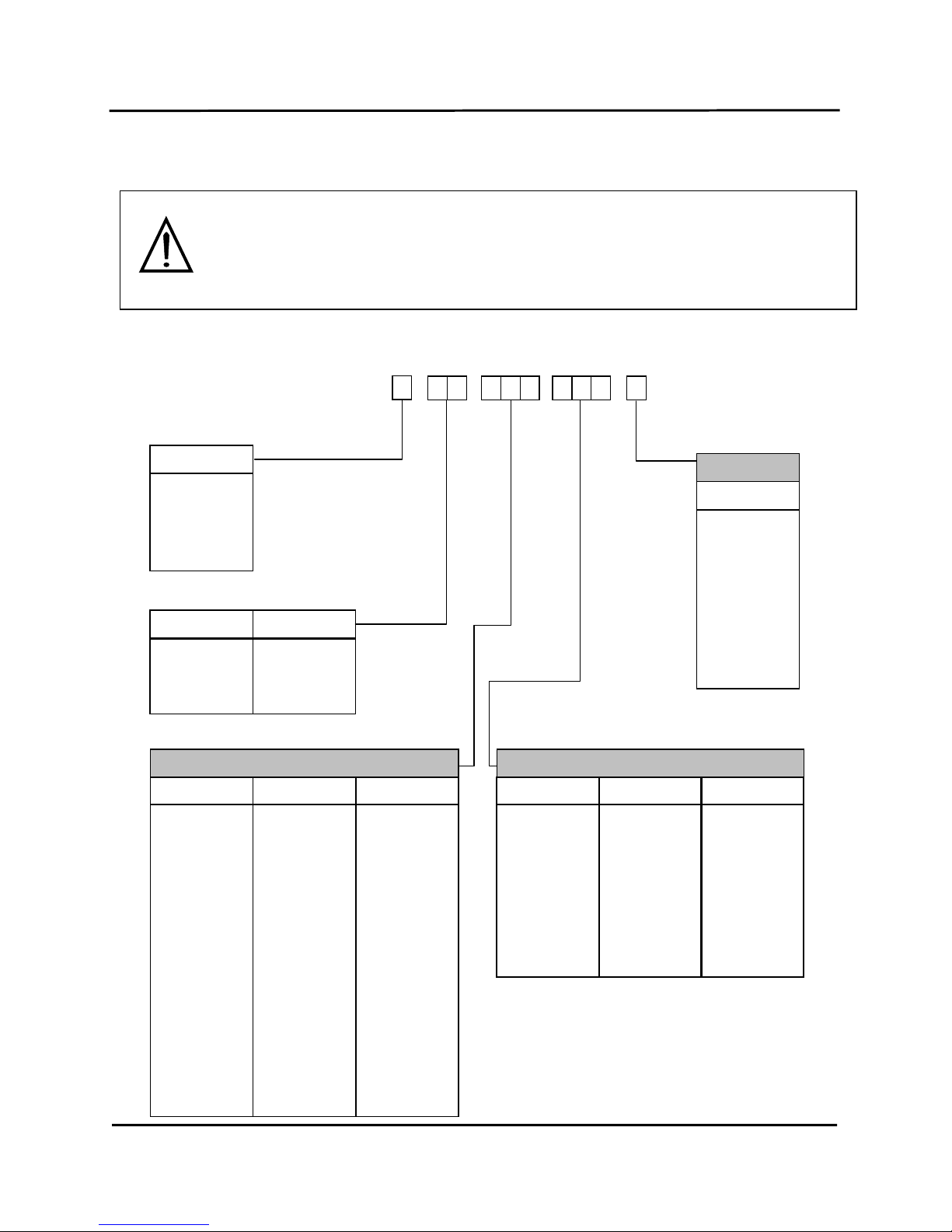
2.1 Model Number Interpretation
Size
1 48*48
2 48*96
3 72*72
4 96*96
Program
C None
P Program
Input
R RTD
T TC
L Linear
Output 1
0 None
1 Relay
2 Volt Pulse
3 4~20mA
5 1ϕ SSR
6 3ϕ SSR
7 Motor V
8 1ϕ SCR
9 3ϕ SCR
A
0~5V
B 0~10V
C 1~5V
D 2~10V
Output 2
0 None
1 Relay
2 Volt Pulse
3 4~20mA
A
0~5V
B 0~10V
C 1~5V
D 2~10V
A
larm
0 None
1 1 alarm
2 2 alarms
3 3 alarms
Manual
E English
C Chinese
K Korean
Table III
A
ux.
0 None
1 4~20mA
2 0~20mA
A
0~5V
B 0~10V
C 1~5V
D 2~10V
Input 2
0 None
1 4~20mA
2 0~20mA
A
0~5V
B 0~10V
C 1~5V
D 2~10V
Table II
---
DC10 0
Table I
0 None
1 RS-232
2 RS-485
Comm.
DC1010/1020/1030/1040 Product Manual
2

2.2 Specification
TECHNICAL DATA
Type of Input
TC (K, J, R, S, B, E, N, T, W, PL II, U, L), RTD (Pt100Ω, JPt100Ω, JPt50Ω)
Linear (-10~10mV, 0~10mV, 0~20mV, 0~50mV, 10~50mV)
Input Sampling Time 500 ms
PV Input
Input Resolution 14 bit (each)
PV/SP Indication 4-digit, 7 segment display
Constant Value Storage System
Non-volatile memory (EEPROM)
Indication
Indication Accuracy
± 0.5%FS
Proportional Band (P) 0~200% (On/Off action at P=0)
Integral Time (I) 0~3600 sec (PD action at I=0)
Derivative Time (D) 0~900 sec (PI action at D=0)
Control Mode
Cycle Time
0~150 sec (4~20mA 0, SSR1, relay10)
Relay Output Contact, SPST(DC1010)/SPDT(1020,1030,1040), 3A/240VAC
Voltage Output Voltage Pulse, 20VDC/20mA
Linear Output 4~20mA, 0~5V, 0~10V, 1~5V, 2~10V
Motor Control Output Three Position Step Control (Time proportional motor control)
Output
Others
1ϕ SSR, 3ϕ SSR, 1ϕ SCR, 3ϕ SCR
Alarm Channel 3 channels (optional)
Mode 17 alarm mode available
Timer Flicker alarm, continued alarm, on delay timer alarm
Output Signal SP, PV
Aux. Output
Type of Output 4~20mA, 0~20mA, 0~5V, 0~10V, 1~5V, 2~10V
Type of Input 4~20mA, 0~20mA, 0~5V, 0~10V, 1~5V, 2~10V 2nd Input
(RSP)
Sampling Time 500 ms
Pattern/Segment 2 pattern/ 8 segment (each)
Program
Availability Pattern link & repeat, program/segment end alarm
Communication
Type of Communication RS-232, RS-485
Rated Power Supply
Voltage & Frequency
AC 90-240V, 50/60Hz or DC15-50V, 4VA
Power Consumption Max. 8VA
Storage Temperature
-25°C~65°C
Ambient Temperature
0°C~50°C
General
Specifications
Ambient Humidity 50~85% RH (no condensation)
INPUT ACTUA TIONS
K
0.0~200.0, 400.0, 600.0, 800.0, 1000, 1200 °C
J
0.0~200.0, 400.0, 600.0, 800.0, 1000, 1200 °C
R
0.0~1600, 1769 °C
S
0.0~1600, 1769 °C
B
0.0~1820 °C
E
0.0~800, 1000 °C
N
0.0~1200,1300 °C
T
0.0~400.0, 200.0 °C, 0.0~350.0 °C
W
0.0~2000, 2320 °C
PL II
0.0~1300, 1390 °C
U
-199.9~600.0, 200.0 °C, 0.0~400.0 °C
TC
L
0.0~400.0, 800.0 °C
Pt100
-199.9~600.0, 400.0, 200.0 °C, 0.0~200.0, 400.0, 600.0 °C
JPt100
-199.9~600.0, 400.0, 200.0 °C, 0.0~200.0, 400.0, 600.0 °C
RTD
JPt50
-199.9~600.0, 400.0, 200.0 °C, 0.0~200.0, 400.0, 600.0 °C
AN1 -10~10mV
AN2 0~10mV
AN3 0~20mV
AN4 0~50mV 0~20mA, 0~1V, 0~5V, 0~10V
Linear
AN5 10~50mV 4~20mA, 1~5V, 2~10V
DC1010/1020/1030/1040 Product Manual
3
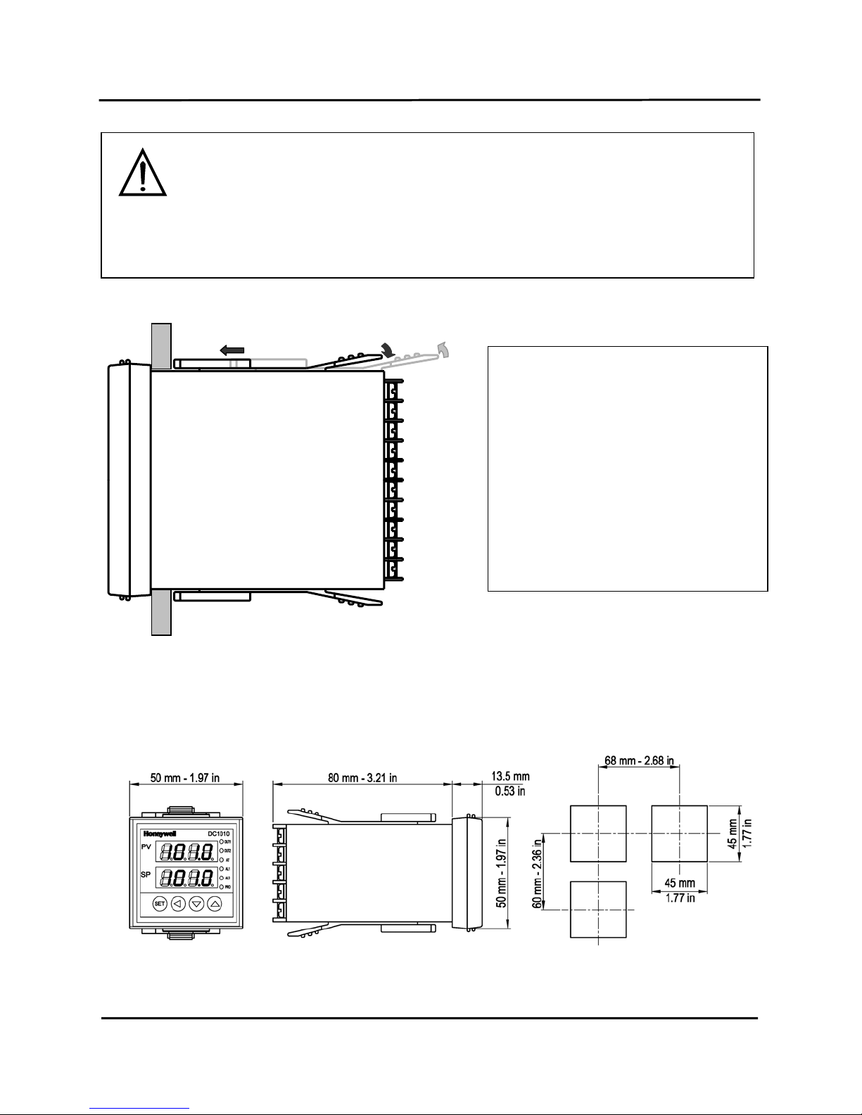
2.3 Mounting
CAUTION
Installation Precautions
The controller can be mounted on either a vertical or tilted panel using the mounting
bracket supplied. Adequate access space must be available at the back of the panel fo
r
installation and servicing activities.
Failure to comply with these instructions may result in product damage.
Side View
1 - Put the mounting bracket in the rail on
the top & bottom of the case.
2 - Bend the grip of the bracket & slide
the bracket along the rail until the case
is secured against the panel.
3 - Put the grip of the bracket on the
groove to fasten the case to the panel.
2.4 External Dimension
2.4.1 DC1010
DC1010/1020/1030/1040 Product Manual
4
 Loading...