

Page 1
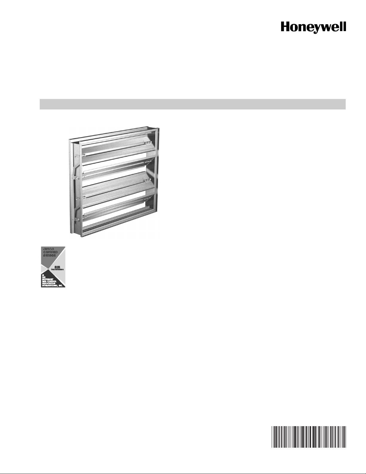
D2 (Former D642), D3 (Former D640)
CONTROL DAMPERS
FEATURES
Frame:
• Standard frames utilize heavy-duty 5 in. (12.7 cm) x 1 in.
(0.25 cm) 16 ga. galvanized steel hat channel frame,
designed for installation inside ductwork. Reinforced
corners. Low profile head and sill on dampers less than 17
in. (43.2 cm) high.
Frame Options:
• Stainless steel and aluminum (14 and 12 gage galvanized
steel only).
• Single flange (either side of frame) or double flange (both
sides of frame). (See Fig. 2.)
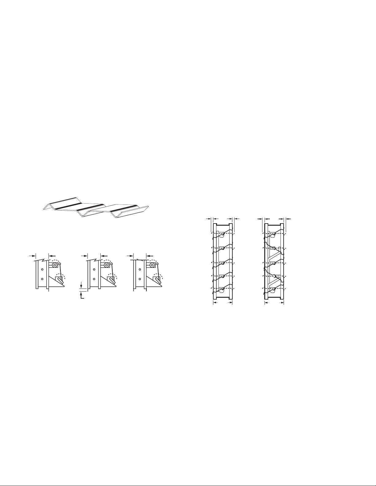
Flange:
• Additional 1 1/2 in. on each side.
Blades:
• Standard 3-V blades are fabricated from a single thickness
of 16 ga. galvanized steel incorporating three longitudinal
structural V-grooves (each running the full length of the
blade). (See Fig. 1.) This blade has low to medium velocity
and pressure capabilities.
Honeywell International, Inc. certifies that the
models D2, and D3 shown herein are licensed to
bear the AMCA Seal. The ratings shown are
based on tests and procedures performed in
accordance with AMCA Publication 511 and
comply with the requirements of the AMCA
Certified Ratings Programs. The AMCA Certified
Ratings Seal applies to air performance ratings
only. March 2008.
The D2, D3 Control Dampers are ruggedly built with 3-V style
blades for application as automatic control or manual
balancing dampers in low to medium pressure and velocity
systems. A wide range of electric or pneumatic actuators are
available for these models.
The D2 series is an ultra low leakage control damper which
includes blade and jamb seals.The D3 series is a general
purpose damper intended for applications where low leakage
performance is not necessary.
Axles:
• 1/2 in. (1.3 cm) diameter square plated steel axles
positively locked to the blades eliminate slippage between
blades and axles. Removable shaft extends 6 in. (15.2 cm)
beyond frame. Optional stainless steel construction.
Bearings:
• Molded synthetic (acetal) bearings rotate in a polished
extruded frame raceway. Extremely low friction and long
operating life result from this advanced design. Bronze or
stainless steel bearings are optional.
Linkage:
• Blade-to-blade linkage (for parallel or opposed blade
action) is concealed within the frame.
• Linkage is engineered to accurately control each and every
blade without need for adjustment. Plated steel
construction ensures a long corrosion free life.
Seals:
• D2 Only: Flexible stainless steel compression-type jamb
seals (between blade ends and side frames) and extruded
vinyl blade seals (between blade edges) reduce leakage.
Silicone or blade seals are optional.
Sizing:
• Nominal sizing results in 1/4 in. undersizing on each side.
Actual sizing available as option.
PRODUCT DATA
Features ............................................................................ 1
Specifications .................................................................... 2
Ordering Information ......................................................... 2
Contents
63-2598-09
Page 2
D2 (FORMER D642), D3 (FORMER D640)
SPECIFICATIONS
Size Limitations:
Pressure:
2 1/2 in. - 5 in. (622 Pa - 1245 Pa) pressure differential.
Velocity:
2000 fpm - 3000 fpm (10.2 m/s - 15.2 m/s).
Size Range:
Minimum Size:
One Blade: 6 in. (15.2 cm) W x 6 in. (15.2 cm) H.
Two Blade: 6 in. (15.2 cm) W x 10 in. (25.4 cm) H.
Maximum Size:
Single Section: 48 in. (121.9 cm) W x 72 in. (182.9 cm) H.
Multiple section size unlimited.
NOTE: W and H dimensions furnished 1/4 in. (0.6 cm)
undersize.
Maximum Temperature:180° F (82° C).
NOTE: Temperatures exceeding 180° F (82° C) require
special consideration.
Parallel/Opposed Blade Operation (Fig. 3)
Control dampers are offered with either parallel or opposed
blades (silicone or vinyl blade seals are optional). Each style
has distinguishing characteristics regarding fan performance
control and change in air velocity profile:
— Parallel blade operation is preferred:
— When the damper makes up a significant portion
of the total system pressure loss.
— When greater control is required near the top end
of the volume operating range or for systems
requiring two position (fully open or fully closed)
operation.
— Parallel blades should not be used upstream of
critical components due to uneven airflow.
— Opposed blade operation is preferred:
— When the damper doesn’t make up a significant
portion of the total system pressure loss.
— For applications where it is necessary to maintain
even distribution of air downstream from the
damper.
— For ducted outlets.
— Opposed blade dampers must open farther to
obtain the same airflow resistance as parallel
blade dampers.
M20586
1-1/4 (32)
MAX.
(TYPICAL)
1-1/4 (32)
MAX.
(TYPICAL)
Fig. 1. 3-V blade.
5-1/8
(130)
SINGLE FLANGE
Fig. 2. Flange options.
5-1/8
(130)
1-1/2 (38) (TYPICAL)
SINGLE REVERSED
FLANGE
5-1/4
(132)
DOUBLE FLANGE
M23950
5 (127)
PARALLEL BLADES
5 (127)
OPPOSED BLADES
Fig. 3. Parallel and opposed blades.
M23951
ORDERING INFORMATION
When purchasing replacement and modernization products from your TRADELINE® wholesaler or distributor, refer to the
TRADELINE
®
Catalog or price sheets for complete ordering number.
If you have additional questions, need further information, or would like to comment on our products or services, please write or
phone:
1. Your local Honeywell Automation and Control Products Sales Office (check white pages of your phone directory).
2. Honeywell Customer Care
1885 Douglas Drive North
Minneapolis, Minnesota 55422-4386
In Canada—Honeywell Limited/Honeywell Limitée,
International Sales and Service Offices in all principal cities of the world. Manufacturing in Australia, Canada, Finland, France,
Germany, Japan, Mexico, Netherlands, Spain, Taiwan, United Kingdom, U.S.A.
63-2598—09 2
Page 3

D2 (FORMER D642), D3 (FORMER D640)
Multi-Section Assembly
Dampers larger than the maximum single section size will be
made up of equal size sections which can be jackshafted
together so that all sections operate together. A damper larger
than the maximum single section size can only ship two
sections wide and will be jackshafted together requiring one
actuator drive location as shown in Fig. 4. (Max. section is 48
in. x 74 in.)
NOTE: Dampers larger than 48 in. x 74 in. (1219 mm x
1880 mm) are not intended to be structurally self-supporting. Additional horizontal bracing is recommended to support the weight of the damper and
vertical bracing should be installed as required to hold
against system pressure.
and temperature limitations shall be submitted for approval
showing damper suitable for pressures to 5 in. (12.7 cm) wg,
velocities to 3,000.0 ft./min. and temperatures to 180 F (82 C).
Testing and ratings to be in accordance with AMCA Standard
500. Basis of design is Honeywell's model D3.
Low-Leakage Volume Control Dampers
Control dampers meeting the following specifications shall be
furnished and installed where shown on plans and/or as
described in schedules. Dampers shall consist of: a 16 ga.
galvanized steel channel frame with 5 in. (12.7 cm) depth;
triple V type blades fabricated from 16 ga. galvanized steel;
blades shall be completely symmetrical relative to their axle
pivot point, presenting identical resistance to airflow in either
direction or pressure on either side of the damper; 0.5 in.
(1.3 cm) diameter plated steel axles turning in synthetic
(acetal) sleeve bearings; and external (out of the airstream)
blade-to-blade linkage. Standard blade seals shall be extruded
vinyl. Standard jamb seals to be flexible stainless-steel
compression type to prevent leakage between blade end and
damper frame. Damper manufacturer's printed application and
performance data including pressure, velocity and temperature
limitations shall be submitted for approval showing damper
suitable for pressures to 5 in. (12.7 cm) wg, velocities to
3,000.0 ft./min. and temperatures to 180 F (82 C). Testing and
ratings to be in accordance with AMCA Standard 500. Basis of
design is Honeywell's model D2.
M23949
Fig. 4. Multiple section damper.
Guide Specifications
Standard Volume Control Dampers
Control dampers meeting the following specifications shall be
furnished and installed where shown on plans and/or as
described in schedules. Dampers shall consist of: a 16 ga.
galvanized steel channel frame with 5 in. (12.7 cm) depth;
triple V type blades fabricated from 16 ga. galvanized steel;
blades shall be completely symmetrical relative to their axle
pivot point, presenting identical resistance to airflow in either
direction or pressure on either side of the damper; 0.5 in.
(1.3 cm) diameter plated steel axles turning in synthetic
(acetal) sleeve bearings; and external (out of the airstream)
blade-to-blade linkage. Damper manufacturer's printed
application and performance data including pressure, velocity
5.0 INCHES WG
5
4.0 INCHES WG
4
3
PRESSURE
(INCHES WG)
2.5 INCHES WG
2
BLADE
BEARING
SHAFT
EXTENSION
(OPTIONAL)
AXLE
LINKAGE
BLADE SEAL
(D2 ONLY)
Fig. 5. Damper components.
Selection Criteria
74
60
48
DAMPER
HEIGHT
(INCHES)
3000 FPM
36
24
FRAME
2500 FPM
JAMB SEAL
(D2 ONLY)
2000 FPM
M20591B
1
0
0 12 24 36 48
DAMPER WIDTH (INCHES)
M23952
12
0
0 12 24 36 48
3 63-2598—09
DAMPER WIDTH (INCHES)
M23953
Page 4

D2 (FORMER D642), D3 (FORMER D640)
Performance Data
Table 1. D2, D3 Pressure and Velocity Limits.
Damper Size
in inches
Maximum
System
Pressure
Maximum
System
Velocity
12 x 12 5.0 in. wg 3000 fpm
24 x 24 5.0 in. wg 3000 fpm
36 x 36 4.0 in. wg 2500 fpm
48 x 48 2.5 in. wg 2000 fpm
NOTE: D2 and D3 will withstand higher pressures and
velocities. Displayed ratings are conservative to
prevent misapplication. Consult Honeywell if you
have an application outside these limitations.
Actuator Torque Multiplier
Table 2. Actuator Torque Multiplier
Pounds Per
Damper
D3 5 lb-in/SF
D2 7 lb-in/SF
NOTE: Assumes 1,500 fpm.
Square Foot
Leakage Data
Leakage testing was conducted in accordance with AMCA
Standard 500D and is expressed as cfm/ft
area. All data has been corrected to represent standard air at
a density of 0.075 lb/cubic ft. (See Fig. 6)
6.0
5.0
4.0
3.0
2.0
1.0
.8
.6
.5
.4
.3
.2
STATIC PRESSURE DIFFERENCE (IN. WG)
1
D2
2 3 5 6 8 10 20 30 50 6080
4 150
AIR LEAKAGE (CFM/FT2)
Fig. 6. D2, D3 leakage data.
Table 3. Pressure Loss Coefficient (in. wg).
12x1224x2436x3612x4848x
AMCA Figure 5.3 1.52 0.67 0.43 0.7 1.2
2
of damper face
D3
100
40
M23317A
12
AMCA Figure 5.2 2.25 1.19 0.67 0.91 1.7
AMCA Figure 5.5 3.64 2.28 1.89 2.15 2.84
NOTE: Data is corrected to standard air density. Average of
4,000 fpm.
Pressure loss can be determined using the following:
ΔpCoV 4005⁄()
×=
2
where
Δp = pressure drop (in. wg)
= pressure loss coefficient
C
o
V = face velocity (fpm)
5 lb-in/SF
7 lb-in/SF
By using this Honeywell literature, you agree that Honeywell will have no liability for any damages arising out of your use or modification
to, the literature. You will defend and indemnify Honeywell, its affiliates and subsidiaries, from and against any liability, cost, or damages,
including attorneys’ fees, arising out of, or resulting from, any modification to the literature by you.
Automation and Control Solutions
Honeywell International Inc. Honeywell Limited-Honeywell Limitée
® U.S. Registered Trademark
© 2008 Honeywell International Inc.
63-2598—09 M.S. Rev. 04-08
 Loading...