

Page 1

ComfortPoint Open
CPO-VAV2A
Installation Instructions
Contents
Installation ............................................................ 1
Safety instructions ........................................ ... .... . 1
CPO-VAV2A controller dimensions ......................2
Mounting CPO-VAV2A on VAV box
electronics enclosure ............................................3
Mounting the CPO-VAV2A on round ductwork .....4
Mounting Caution .................................................4
Air Flow Pick-up ....................................................5
Serial Number Label .............................................5
Terminal Settings ..................................................6
CPO-VAV2A Terminal Overview ..........................6
Automatic MAC addressing ..................................6
Manual MAC addressing ......................................7
Analog Input .........................................................8
Analog Output .......................................................9
Digital Output ........................................................9
Integrated Actuator ............................. .................. 9
Communication .......................................... ......... 10
BACnet MS/TP ...................................................10
Sylk™ Bus ..........................................................10
Power Supply .....................................................10
Controller startup ................................................11
Cabling ............................................................... 11
Sylk Bus cable specification ...............................11
Connection drawings ..........................................11
Connecting the Honeywell
BACnet Wi-Fi Adapter ........................................17
Federal communications
commission (FCC) statement .............................18
Installation
This document provides the information needed to install
CPO-VAV2A controller. It describes the dimensions, mounting
details and the terminal connections to these devices.
Safety instructions
• When performing any work (installation, mounting, startup), all instructions given by the manufacturer and in
particular the safety instructions provided in this document
are to be observed.
• The CPO-VAV2A controller must be installed and mounted
only by authorized and trained personnel.
• If the unit is modified in any way, except by the
manufacturer, all warranties concerning operation and
safety become invalid.
• Make sure that applicable local standards and regulations
are observed at all times.
• Use only Honeywell supplied or approved accessories.
• Before the system is dismantled, disconnect the power
supply by either removing the power terminal block from
the controller, or by means of local isolation. Read the
following caution note carefully.
Caution
Disconnect the power supply before you start to install the CPO-VAV2A controller. Do not reconnect the power supply until you have completed the installation.
Trademark Information
ComfortPoint
International Inc.
BACnet
Copyright 2017 – Honeywell International Inc. EN1B-0022 IE10 R0717
TM
Open is a trademark of Honeywell
®
is a registered trademark of ASHRAE Inc.
Page 2
INSTALLATION
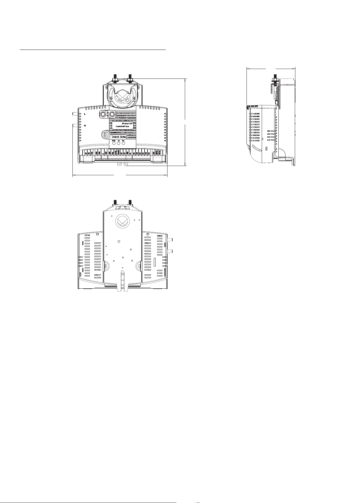
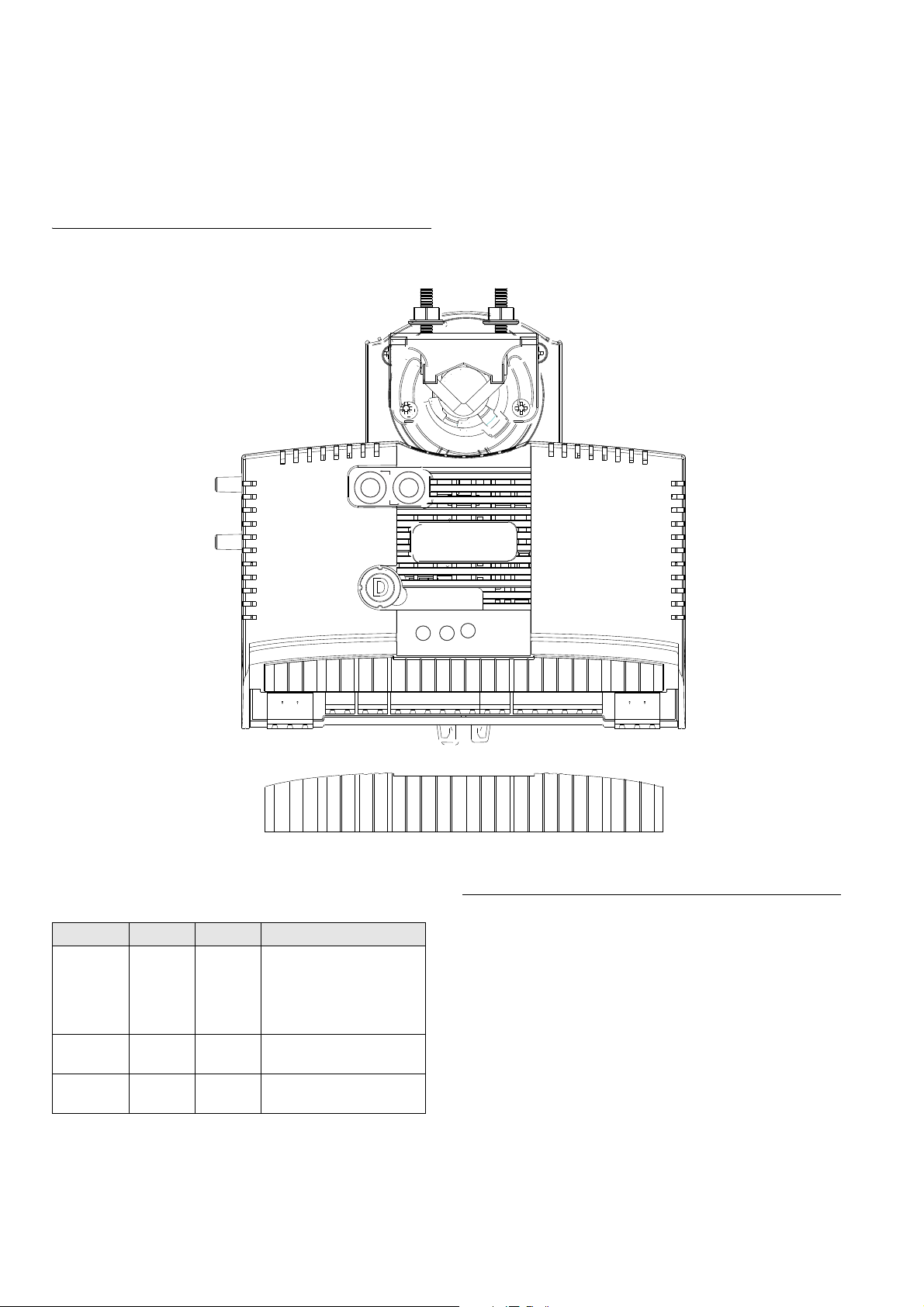
157.9
81.1
145.6
CPO-VAV2A controller dimensions
1
Figure 1 CPO-VAV2A controller dimension.
Before mounting CPO-VAV2A controller
Before mounting the CPO-VAV2A onto the VAV box damper
shaft, do the following:
1. Ensure that the diameter of the damper shaft is within the
allowed limits (round: 8…16 mm, square: 6…13 mm).
2. Ensure that the damper shaft has a length of at least 40
mm.
3. Determine the direction (CW or CCW) in which the damper
shaft rotates to open the damper. The installation
procedure varies depending on the damper direction.
4. Determine the angle of the damper opening (can be
adjusted in increments of 5.5°).
If damper rotates CW to open
If the damper rotates clockwise (CW) to open, mount the
CPO-VAV2A as follows:
1. Manually open the damper.
2. Push down the declutch button of the CPO-VAV2A, and
while holding it down, manually rotate its shaft adapter fully
to the clockwise position.
3. Mount the CPO-VAV2A to the VAV box damper shaft.
4. Set the mechanical end limits of the CPO-VAV2A (see
Figure 2 on page 3 ). When the CPO-VAV2A closes, the
damper will thus rotate
5. CCW until the mechanical end limits are reached.
If Damper Rotates CCW to Open
If the damper rotates counterclockwise (CCW) to open, mount
the CPO-VAV2A as follows:
1. Manually open the damper.
2. Push the declutch button of the CPO-VAV2A, and while
holding it down, manually rotate its shaft adapter fully to
the counterclockwise position.
3. Mount the CPO-VAV2A to the VAV box damper shaft.
4. Set the mechanical end limits of the CPO-VAV2A (see
Figure 2). When the CPO-VAV2A closes, the damper will
EN1B-0022 IE10 R0717 2
Page 3
thus rotate CW until the mechanical end limits are
1
2
3
1
2
For S
erial No. Label
For Safety Caution
Back view
30 mm
30 mm
210 mm
297 mm
F
o
r S
erial No. Label
2
1
Back view
30
m
m
3
0
m
m
21
0
m
m
297 m
m
reached.
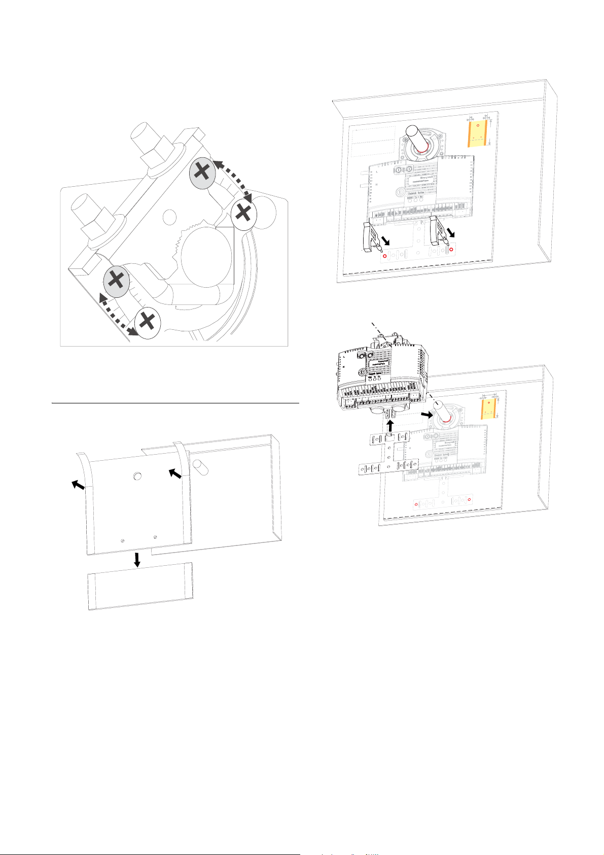
Figure 2 Setting the mechanical end limits
INSTALLATION
Figure 4 Drilling 2 holes per template indication
Mounting CPO-VAV2A on VAV box electronics enclosure
Figure 3 Paste the drilling template in VAV box electronics enclosure
Figure 5 Attach controller on damper shaft and fix with anti-rotation bracket
3 EN1B-0022 IE10 R0717
Page 4
INSTALLATION
1
2
3
3
4
2
4
1
2
1
2
3
3
4
4
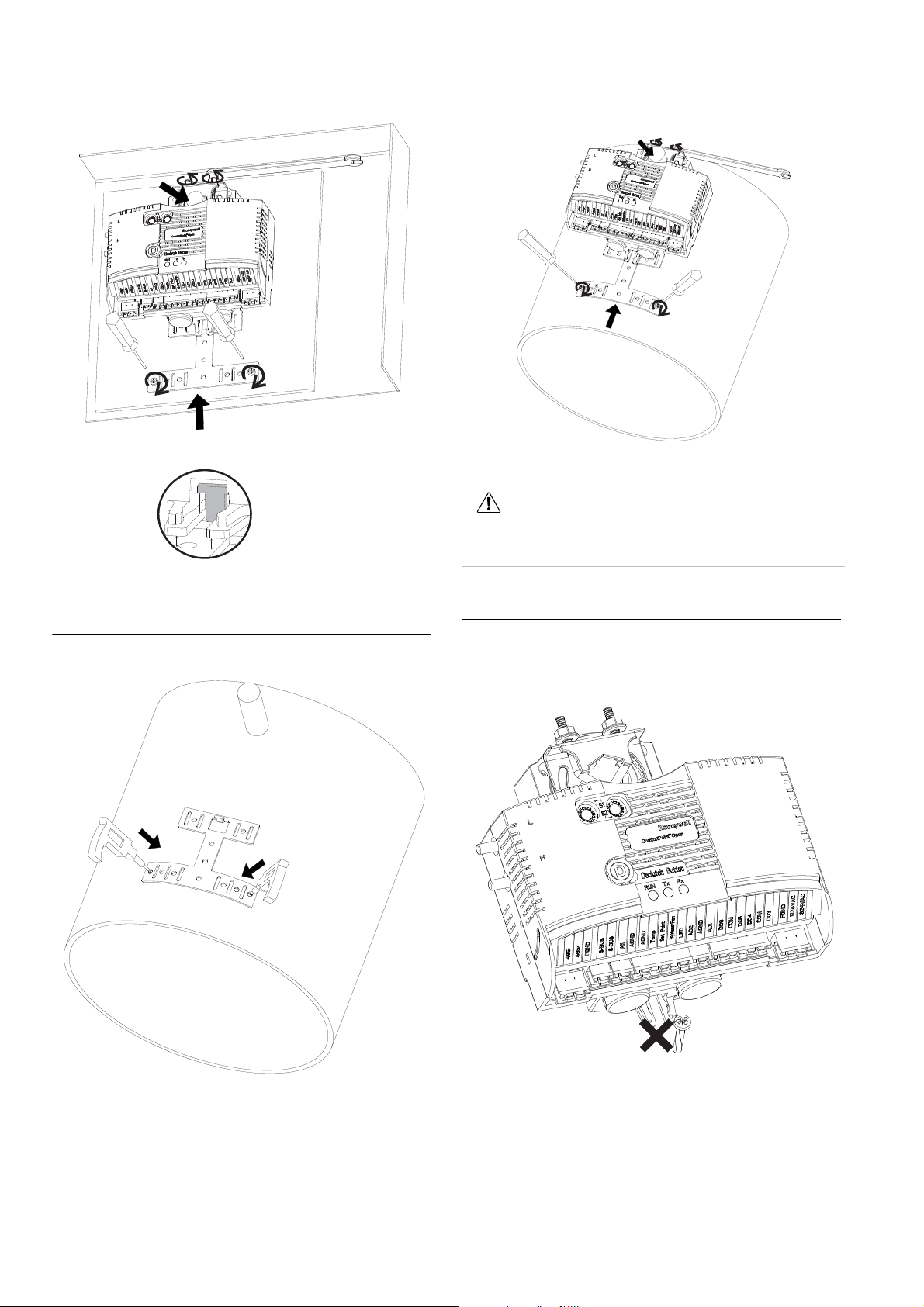
Figure 6 Fasten screws of bracket and U-Bolt to shaft
Figure 8 Attach controller to shaft and Fasten screws of bracket and U-bolt
Caution
Round ductwork installation is not applicable for America and Canada without appropriate enclosure.
Mounting the CPO-VAV2A on round ductwork
Mounting Caution
Use the anti-rotation bracket and screws included in the unit
pack to mount the CPO-VAV2A. DO NOT use the single screw
to mount the CPO-VAV2A.
Figure 7 Drill 2 holes for bended bracket
EN1B-0022 IE10 R0717 4
Figure 9 Do not use the single screw to mount the CPO-VAV2A
Mounting the CPO-VAV2A unevenly with damper housing can
damage actuator. Mount the actuator flush with the damper
housing or add a spacer between the anti-rotation bracket and
the VAV box damper housing.
Page 5
INSTALLATION
VAV box
damper shaft
VAV box
damper housing
Spacer
-LOW
+HIGH
AIRFLOW
DIRECTION
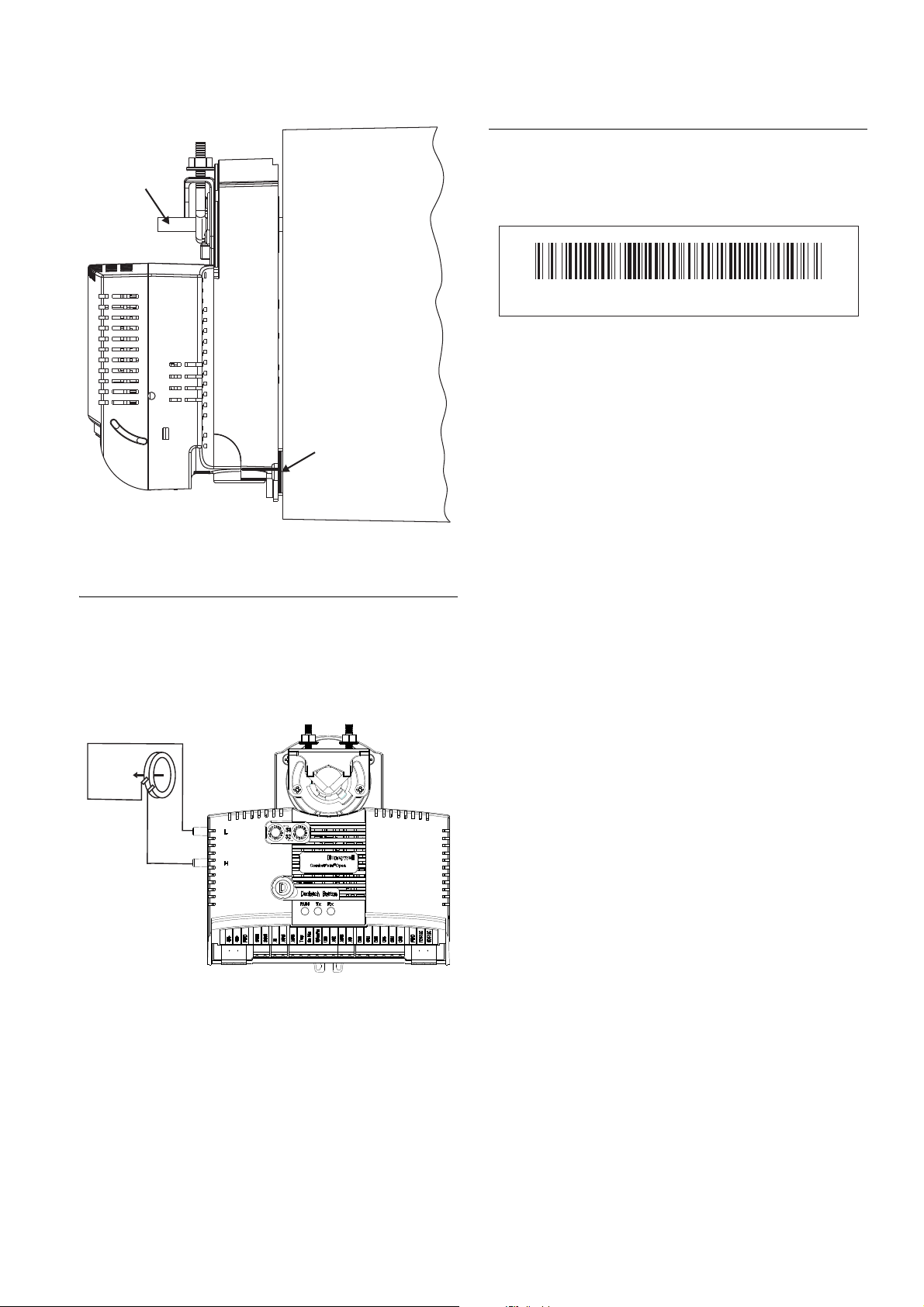
130228CP- V2A10200200075
Serial Number Label
There is a separate label with product serial number in the unit
pack. The user can choose to paste this label on the front of
housing to easily check the product serial number.
Figure 12 Serial Number Label Example
Figure 10 Mounting the CPO-VAV2A with washer/spacer
Air Flow Pick-up
Connect the air flow pick-up to the two connectors on the
CPO-VAV2A. See Figure 11. Connect the high pressure or
upstream tube to the air flow pick-up connector labeled (H)
and the low-pressure or downstream tube to the connector
labeled (L).
Figure 11 Air flow pick-up connection
Best practice for zero calibration of air flow sensor
The controller must be powered up for a minimum of 1 hour
before performing the zero calibration for the air flow sensor.
5 EN1B-0022 IE10 R0717
Page 6
TERMINAL SETTINGS
485-
485+
FGND
S-BUS
S-BUS
AI1
AGND
AGND
Tem p
Set Point
ByPass/Fan
LED
AO2
AGND
AO1
DO6
COM
DO5
DO4
COM
DO3
FGND
N24VAC
S24VAC
RxTxRun
Declutch Button
Honeywell
Comfort Point
TM
Open
L
H
S1
S2
A
B
C
D
E
F
0
1
2
3
4
5
6
7
8
9
A
B
C
D
E
F
0
1
2
3
4
5
6
7
8
9
485-
485+
FGND
S-BUS
S-BUS
AI1
AGND
AGND
Tem p
Set Point
ByPass/Fan
LED
AO2
AGND
AO1
DO6
COM
DO5
DO4
COM
DO3
FGND
N24VAC
S24VAC
Terminal Settings
This section describes the terminal settings on the CPO-VAV2A controller.
CPO-VAV2A Terminal Overview
Figure 13 describes the layout of pins on the CPO-VAV2A controller.
Figure 13 Describes the layout of pins on the CPO-VAV2A controller.
LED operation Automatic MAC addressing
Sr.No LED Label LED Color Description
1 Run Green The LED is Off when there
is no power to the controller.
LED is blinking when the
controller is working
normally.
2 Rx Yellow LED indicates Receive of
3 Tx Yellow LED indicates Transmit of
EN1B-0022 IE10 R0717 6
data on MS/TP bus.
data on MS/TP bus
Controllers with Automatic MAC addressing functionality can
be identified by a label covering the MAC address rotary
switches. This information is also printed on the product label
available on the controller. When a controller with Automatic
MAC addressing feature is powered ON, can assign its own
unique MAC address ranging from 1 to 30. It can also coexist
with other unitary controllers whose MAC addresses are set
manually. The controller can automatically adjust the MAC
address at any time to avoid duplicate addresses in the
network. The automatic MAC address assigned through this
process is retained when the controller is powered OFF.
To disable Automatic MAC addressing, remove th e label on
the rotary switches and set the switches to the manual
Page 7

TERMINAL SETTINGS
address required. By default, the switches are already set to
(0xFF) for controllers that support Automatic MAC addressing.
To enable Automatic MAC addressing again, set the switches
back to (0xFF).
For the controller to support AutoMAC, the boot loader version
must be v2.5.1 or later and the firmware version v2.7.3 or
later.
Attention
The switches are only read by the controller when turned ON. Therefore, whenever the switch positions are changed the power must be removed and reapplied before the new switch positions take effect.
Possible Automatic MAC addressing scenarios
Note
The times provided in the following table are only for information. The actual time taken for resolution of MAC address conflicts may slightly vary.
Scenario Time Remarks
A: Auto MAC controller initial start-up time and acquire MAC address on single BACnet MS/TP bus after power-on (Cold boot or reset).
B: Average initial start-up time and acquire MAC address where all controllers on a single MS/TP bus are Auto MAC controllers.
30 secs 29 Manual MAC controllers.
1 Auto MAC controller that must acquire a MAC address.
Time includes start-up time plus time to acquire MAC address.
260 secs 30 Auto MAC controllers.
All controllers must acquire a MAC address.
Time includes start-up time plus time to acquire MAC address.
Scenario Time Remarks
C: Average time for MAC conflicts to be resolved when an Auto Mac controller is added to an MS/TP bus while Auto MAC process is still operating.
D: Average time for MAC conflicts to be resolved when a Manual Mac controller is added to an MS/TP bus while Auto MAC process is still operating.
E: Average time for MAC conflicts to be resolved when a manual MAC controller with conflicting MAC address is added to an MS/TP bus.
F: Average time for Auto MAC controller restart where all controllers on MS/TP bus are Auto Mac and have previously acquired a MAC address.
Verify that the MAC address remains unchanged after restart when there is no conflicts.
50 secs 15 existing Auto MAC
controllers.
13 existing Manual MAC
controllers.
Add 1 Auto MAC controller
where there is an address
conflict with existing Auto
MAC controller.
50 secs 15 existing Auto MAC
controllers.
13 existing Manual MAC
controllers.
Add 1 Manual MAC
controller where there is an
address conflict with
existing Auto MAC
controller.
30 secs 15 Auto MAC controllers.
14 Manual MAC controllers. Add 1 Manual MAC
controller where there is an
address conflict with an
Auto MAC controller.
25 secs 30 Auto MAC controllers.
All controllers have all acquired MAC address from previous operation.
No MAC address conflicts exist before power down and restart.
All controllers retain existing MAC address after restart.
Time includes start-up time plus time to verify there are no MAC address conflicts.
Manual MAC addressing
Attention
Address Switch 1 & Address Switch 2 are HEX switches which are used in combination for addressing the CPO-VAV2A controller. The valid address for CPO-VAV2A is from 1 to 30.
7 EN1B-0022 IE10 R0717
Page 8

TERMINAL SETTINGS
S1
S2
A
B
C
D
E
F
0
1
2
3
4
5
6
7
8
9
A
B
C
D
E
F
0
1
2
3
4
5
6
7
8
9
There are two Hex switches on the controller: S1 and S2, as
shown in Figure 14.
Figure 14 CPO-VAV2A Hex Switches Layout
Set S1 to the lower nibble of the address and S2 to the higher
nibble of the address.
Example: If you want to set 2 as the MAC address, S1 should
be set to 2 and S2 should be set to 0.
Similarly if you want to set 17 as the MAC address, S1 should
be set to 1 and S2 should be set to 1.
The following table illustrates the S1 and S2 switch settings
for the corresponding MAC addresses.
S1 Switch S2 Switch MAC Address
101
202
303
404
505
606
707
808
909
A010
B011
C012
D013
E014
F015
0116
1117
2118
3119
4120
5121
6122
7123
8124
9125
A126
S1 Switch S2 Switch MAC Address
B127
C128
D129
E130
Attention
Make sure that each CPO-VAV2A controller on the MS/TP bus has a unique MAC address. Valid address for CPO-VAV2A is from 1 to 30. 0 is reserved for the plant controller while CPO-Studio uses addresses 32 and 35.
It also shall be ensured that CPO-VAV2A, CPVAV/SPC and CP-DIO on the same MS/TP bus
MUST NOT have the same MAC Address.
Analog Input
Analog inputs can be used, for example, to connect the wall
module, or temperature sensor to the controller.
Technical specification
• 4 analog inputs
• AI 1, AI 2, AI 3, and AI 4 are universal, and can be used as
- NTC20K (-50 to +150 deg.C)
- PT1000 (-50 to +150 deg.C)
- 0 to +10 V
- 0(4) to 20 mA (with an external resistor of 499
0.25%)
- Potential Free Contact (Digital Input)
• AI 2, AI 3 and AI 4 can also be used as wall module inputs:
- Space Temperature Sensor
-Set Point
- Bypass/Fan Speed
• 12-bit A/D resolution
The CPO-VAV2A controller supports wall modules:
•TR2x
•TR40
•TR42
• T7560
• T7460
• C7110C/D
• C7262A
• CP-WM-FCU
•CP-CM
• CP-US-WM-FCU
EN1B-0022 IE10 R0717 8
Page 9

• CP-US-WM-VAV
COM
SENSOR
SETPOINT
BYP/FAN
LED
BYP/RTN
LED/RTN
T7460
Terminals
AGND
Temp
Set Point
ByPass/Fan
LED
VAV
Terminals
1
2
3
4
5
6
7
1
2
3
4
5
COM
SENSOR
SETPOINT
BYP/FAN
LED
Bypass**
Humidity
T7560
Terminals
AGND
Temp
Set Point
ByPass/Fan
LED
VAV
Terminals
1
2
3
4
5
6
7
1
2
3
4
5
24 Vac
8
COM
CO2 Output 0...10V
24 VAC/DC
NTC 20kOhm
SETPT. 1...10kOhm
LED INPUT
OCCUPANCY
C7110D
Terminals
AGND
Temp
Set Point
ByPass/Fan
LED
VAV
Terminals
1
2
3
4
5
6
7
1
2
5
6
AGND
A1
3
4
V+
Com AC/DC
TEMP
TEMP
OUT1: CO2
OUT2: CO2
RELAY NO
C7262A
Terminals
AGND
Temp
Set Point
ByPass/Fan
LED
VAV
Terminals
1
2
3
4
5
6
7
1
2
AGND
A1
4
RELAY NO
3
Common
Setpoint
MSTP+
Temperature Sensor
MSTP-
24 Vac/dc input
CP-CM
Terminals
AGND
Temp
Set Point
ByPass/Fan
LED
VAV
Terminals
1
2
3
4
5
6
1
2
3
24 Vac/dc input
Occupancy
(24Vac input contact)
Temperature Sensor
Setpoint
FAN/Bypass
Common
CP-WM
Terminals
AGND
Temp
Set Point
ByPass/Fan
LED
VAV
Terminals
1
2
3
4
5
6
1
2
3
• CP-WM-VAV
Attention
Resolution of the PT1000 sensor: 1 Fahrenheit or
0.6 Centigrade.
Do not use the datapoint associated to PT1000 in
control logic which requires a resolution less than
1 Fahrenheit.
The analog input with PT1000 can be used in
control loops only when connected to
CPO-VAV2A via a transducer with 0-10V rating.
Additionally, you must use the ComfortPoint Open
Studio tool to define custom characteristics which
matches the selected transducer.
The PT1000 sensors connected directly with CPO-VAV2A can be used only for monitoring and reporting purposes.
TERMINAL SETTINGS
Figure 17 Connection of C7710D with CPO-VAV2A
The connection between CPO-VAV2A and wall modules are
illustrated in Figure 15 through Figure 21.
Figure 15 Connection of T7460 with the CPO-VAV2A
Figure 16 Connection of T7560 with CPO-VAV2A
Figure 18 Connection of C7262A with CPO-VAV2A
Figure 19 Connection of CP-CM with CPO-VAV2A
Figure 20 Connection of CP-WM-VAV with CPO-VAV2A
Attention
The CPO-VAV2A controller does not contro l th e LCD display of the T7560 Wall module. It handles the temperature sensor input, Bypass/Fan, or Fan Control Input. The LCD Display must not be used to get the Effective Occupancy state of the controller.
Figure 21 Connection of TR40 and TR42 with CPO-VAV2A
9 EN1B-0022 IE10 R0717
Page 10

COMMUNICATION
485-
485+
FGND
MSTP Channel
Shied should be continuous
485-
485+
FGND
Internally connected
on T-terminals
Next CPO-VAV2A
Analog Output
Analog outputs can be used, for example, to operate valve or
damper actuators.
Technical specification
• 3 analog outputs
• Analog output (AO1, AO2, and AO3) details
- Voltage: 0-10 V
- Current: max. 10 mA
- Resolution: 12-Bit
- Min. Step: 2.4 mV
- Accuracy: +/- 100 mV
• AO3 (terminal labeled LED) can be used for Wall Module
LED.
Digital Output
The digital outputs are switched by Triac and can be
connected directly to the external relay- the loads are powered
from digital outputs.
Technical specification
• 6 digital outputs, 4 are free while 2 (DO 1 and DO 2) are
internally connected to the integrated actuator
• Output stages:
- Low signal - 0 V
- High signal - 24 VAC
- Type - Triac
• Load per output:
- min. 30 mA
- max. 500 mA
• Non-isolated within 6 digital outputs (first 2 are reserved
internally to drive the integrated actuator)
• Support declutch mechanism to allow the installer to
manually open or close the VAV box damper without
power or software tool
• Shaft adapter: support different round (8 to 16 mm) or
square (6 to 13 mm) shafts
• Noise (dBA at 1 meter maximum): 35
Attention
The actuator cannot be detached from the CPOVAV2A controller.
Avoid mounting the CPO-VAV2A in areas where acid fumes or other corrosive vapors can attack the integrated actuator's metal parts, or in areas where escaping gas or other explosive vapors are present.
Communication
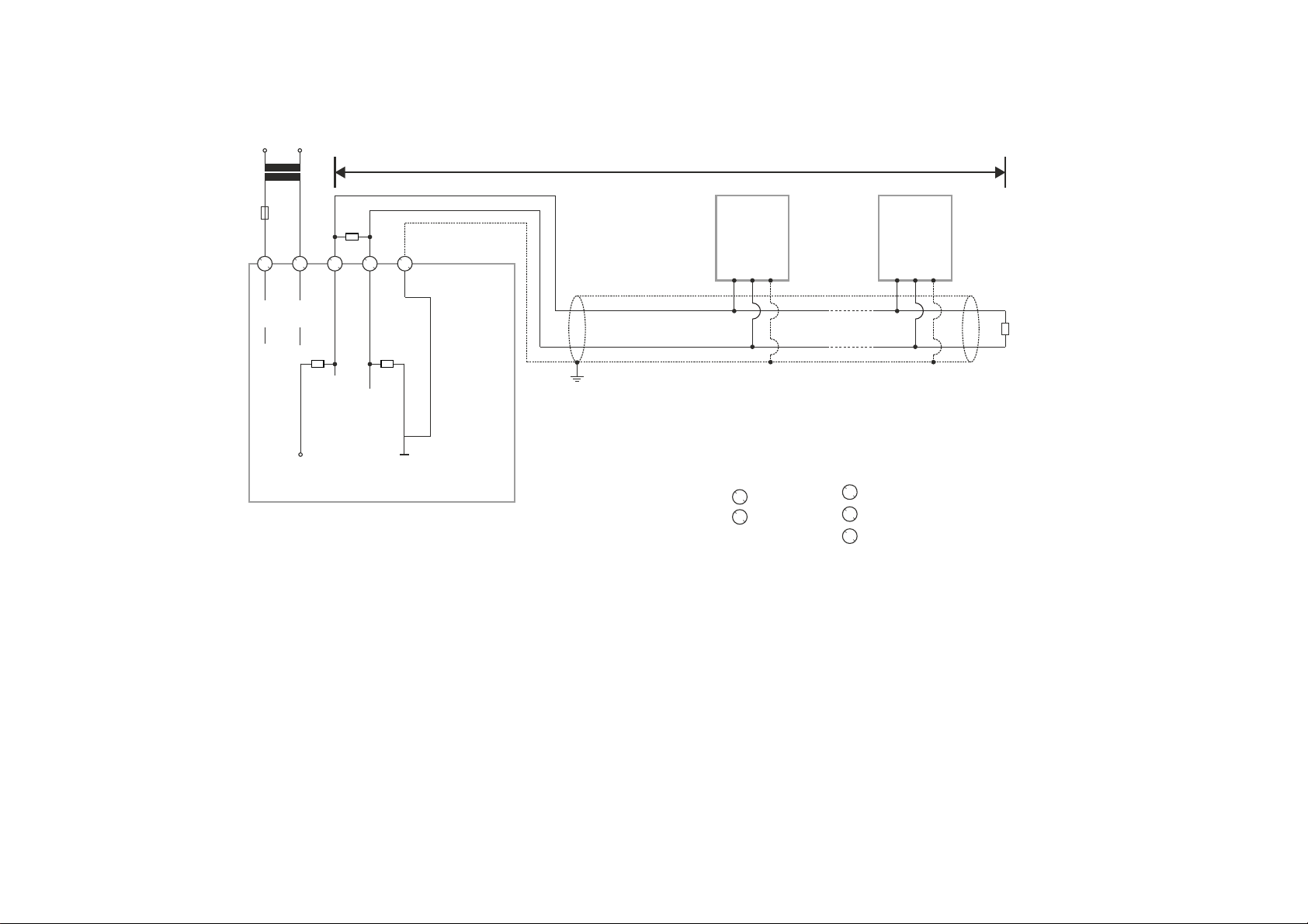
BACnet MS/TP
The CPO-VAV2A controller has one BACnet MS/TP port.
MSTP connection is internally looped in T-terminal and
remains looped after T-terminal is unplugged from the CPOVAV2A controller.
Figure 22 MS/TP Bus Connection
Integrated Actuator
There is an actuator vertically integrated with the CPO-VAV2A
controller centre in-line. The power supply and digital outputs
to the integrated actuator are internally provided by the CPOVAV2A controller, no need of additional wiring to the
integrated actuator from outside of the CPO-VAV2A controller.
Technical specification
• Type: Non Spring Return, Low Torque, Direct Coupled
Actuator (NSR, LT, DCA)
• Control Scheme: Series 60
• Torque Rating: 5 Nm
• Stroke Rating: 95°
• 90° Stroke Timing: 110 +/- 3 sec @ 50Hz, 90 +/- 2 sec @
60Hz
EN1B-0022 IE10 R0717 10
Page 11

CONTROLLER STARTUP
TO CPO-VAV2A
DAISY-CHAINING MULTIPLE ZIOS
TO ZIO
S24VAC
N24VAC
FGND
230 VAC 24 VAC
Sylk™ Bus
The CPO-VAV2A controller has one Sylk port which is a two
wire, polarity insensitive bus that provides both 24VAC power
and communications between a Sylk-enabled sensor and a
Sylk-enabled controller. Using Sylk-enabled sensors saves I/
O on the controller and is faster and cheaper to install since
only two wires are needed and the bus is polarity insensitive.
Sylk sensors are configured using the ComfortPoint Open
Studio.
Transformer requirements for one CPOVAV2A controller
• Voltage: 24 VAC +/- 10% (50/60Hz)
• Power: 15 VA
Note
• Includes Sylkbus and actuator.
• Does not include Triac power. (Allow additional
capacity for equipment controlled from Triacs
where required).
Power consumption by various components
Components Maximum Power (VA)
Control board 8 Sylkbus 3 Actuator 2 Buffer 2
Total 15
Figure 23 Sylk™ Bus Connection
Power Supply
The CPO-VAV2A controller is powered by an external NEC
Class 2 transformer. Power is internally looped in T-terminal
and remains looped after T-terminal is unplugged from the
CPO-VAV2A controller.
Figure 24 Powering CPO-VAV2A through an external transformer
Attention
There are no internal fuses inside T-terminal for looped power supply. The maximum current rating is 9 Amp. Drawing more current can damage the product. Connect an external fuse.
Controller startup
When the controller delivered from the factory is powered up
for the first time, the device instance ID is set to a value
between 1 ~ 30 which is based on the MAC address. If the
MAC address changes, the device instance ID also changes
to match the MAC address. After downloading the application
to the controller, the instance ID is modified to a new value as
defined in the CPO Studio project. Subsequently, the device
instance ID does not change despite the MAC address
changes.
Therefore, to discover this unitary controller from CPO Online
tool with instance ID less than 128, enable the MSTP
channels in the system settings page of plant controller.
See “Managing system settings” section from “CPO Online
User’s Guide (EN2B 0002 IE10)”.
Cabling
This Section describes the specifications for cables used in
making connections to the CPO-VAV2A controller.
Cable Routing
All signal cables (input/output, low voltage) are
communication circuits and should therefore be routed
separately from the line voltage. Minimum distance is 4in (100
mm).
Attention
Avoid using joints in sensor cables.
11 EN1B-0022 IE10 R0717
Page 12

CABLING
Cable lengths and cross sectional areas
Signal type Cross-sectional
Less than or equal to 300 Ft. (100m)
Power supply (24
VAC)
Low current
signals
1.E.g. for 0-10 VDC input, NTC20K, PT1000, dry
contact, 0-10 VDC output.
Less than or equal to 16
AWG (Greater
than or equal
to 1.5 mm
Less than or equal to 20 AW G (Greater th an or
1
equal to 0.5 mm
Attention
The maximum length of a signal cable with 24 VAC supply is 550 ft. (170 m). The max. length of a two-wire, 0-10 Vdc signal cable is 1300 ft. (400 m). The secondary side of the transformer must not be connected to earth ground.
Installing a fuse on the secondary side of the transformer is recommended to protect the devices against incorrect wiring.
Less than or equal to 500 ft. (170 m)
Less than or equal to 14
AWG (Greater than or equal to
2
)
2
Less than or equal to 1300 ft. (400 m)
-
)
Recommended maximum distance
from controller to any Sylk device
Quantity
and type of
device
3 wall
modules,
any type
Single twisted pair, non-
shielded, stranded or solid
18-22 AWG 24 AWG 18-24 AWG
500 ft
(150 m)
400 ft
(120 m)
Standard
thermostat wire, (non-
twisted), shielded or
nonshielded, stranded or
solid
100 ft
(30 m)
Connection drawings
This section describes example connection drawings of the
CPO-VAV2A controller with:
• MS/TP bus
• Sylk bus
• 24 VAC power, and IO connection
MS/TP cable specification
Use Belden 9841 or Equivalent cable with the following
specifications
• An MSTP EIA-485 network shall use shielded, twisted-pair
cable with characteristic impedance between 100 and 130
ohms.
• Distributed capacitance between conductors shall be less
than 100 pF per meter (30 pF per foot).
• Distributed capacitance between conductors and shield
shall be less that 200 pF per meter (60 pF per foot).
• Foil or braided shields are acceptable.
• The maximum recommended length of an MS/TP segment
is 1000 meters.
Sylk Bus cable specification
• Polarity insensitive
• Can use daisy chain wiring for multiple Sylk devices. If
wire size is too thick for two wires in the terminal, use
pigtails.
EN1B-0022 IE10 R0717 12
Page 13
MSTP Bus Connection
L
90 to
120 Ohm
R
T
510
Ω
510
Ω
GND-ISO
5 V-ISO
RS485+
RS485-
CP-VAV/SPC/
CPO-VAV2A #1
CP-VAV/SPC/
CPO-VAV2A #N
R
T
CP-IPC
1
1
2
2
33445
5
24 V
24 V-0
230 V
S24VAC
POWER
N24VAC
BACnet/MSTP
CH+
CH-
FGND
24 V
F1
RS485 +
RS485 -
FGND
RS485 +
RS485 -
FGND
CABLING
NOTES:
Always power the CP-IPC with a transformer separate to the connected BACnet MS/TP modules.
N = max. 30 modules.
13 EN1B-0022 IE10 R0717
Page 14

CABLING
230 V
L
24 V
F1
2
1
24 V
5 V-ISO
3 4 5
24 V-0
510
Ω
RS485+
DIP SWITCH ON
R
T
RS485-
510
Ω
GND-ISO
CPO-PC-6A
Connection (L > 3 m) of RS485 interfaces 1, 2, or 3 (RS485 interface 1 shown) to a BACnet Bus
NOTES
Always power the CPO-PC-6A with a transformer separate to the connected BACnet MS/TP modules.
N = max. 30 modules.
CP-VAV/SPC/
CPO-VAV2A #1
RS485 +
RS485 -
FGND
CP-VAV/SPC/
CPO-VAV2A #N
RS485 +
RS485 -
FGND
R
90 to
120 Ohm
T
EN1B-0022 IE10 R0717 14
Page 15

MSTP Bus Connection
120 ohm
CABLING
120 ohm
Sylk Bus
CP-CORE
®
Connection
S-BUS
534
S-BUS
FNGD
CPO-VAV2A
S-BUS
S-BUS
FNGD
CPO-VAV2A
S-BUS
S-BUS
CPO-VAV2A Sylk sensor 1
15 EN1B-0022 IE10 R0717
Sylk sensor N
Page 16

CABLING
ByPass/Fan
LED
CPO-VAV2A
485-
485+
FGND
S-BUS
S-BUS
AI1
AGND
AGND
Temp
Set Point
DO4
COM
AO2
AO1
DO6
COM
DO5
DO3
FGND
N24VAC
S24VAC
DO1
DO2
TRIAC EQUIVALENT
CIRCUIT
DO for Integrated
actuator
AIRFLOW
PICKUP
L
H
+-
+
24V AC
-
24V AC COM
MSTP Channel
Shied should
be continuous
COM
SENSOR
SETPOINT
BYP/FAN
LED
Bypass**
Humidity
T7560 Terminals
1
2
345
6
7
24 Vac
8
COM
AGND
Stage 3
Stage 2
Stage 1
Line Power
staged reheat Fan
ByPass/Fan
LED
CPO-VAV2A
485-
485+
FGND
S-BUS
S-BUS
AI1
AGND
AGND
Temp
Set Point
DO4
COM
AO2
AO1
DO6
COM
DO5
DO3
FGND
N24VAC
S24VAC
DO1
DO2
TRIAC EQUIVALENT
CIRCUIT
DO for Integrated
actuator
AIRFLOW
PICKUP
L
H
+-
+
24V AC
-
24V AC COM
MSTP Channel
COM
SENSOR
SETPOINT
BYP/FAN
LED
Bypass**
Humidity
T7560 Terminals
1
2
345
6
7
24 Vac
8
COM
Modulating valve :
3 wires external
powered 0...10V device
G0G
Y
AGND
G0G
Y
Wiring Diagram of CPO-VAV2A
Figure 25 Controller wiring diagram for typical VAV application -with Series Fan , staged Reheat, T7560 Wall Module
Figure 26 Controller wiring diagram for typical VAV application - with modulating valves,T7560 Wall Module
EN1B-0022 IE10 R0717 16
Page 17

CABLING
ByPass/Fan
LED
CPO-VAV2A
485-
485+
FGND
S-BUS
S-BUS
AI1
AGND
AGND
Temp
Set Point
DO4
COM
AO2
AO1
DO6
COM
DO5
DO3
FGND
N24VAC
S24VAC
DO1
DO2
TRIAC EQUIVALENT
CIRCUIT
DO for Integrated
actuator
AIRFLOW
PICKUP
L
H
+-
+
24V AC
-
24V AC COM
MSTP Channel
Shied should
be continuous
COM
Modulating valve :
3 wires external
powered 0...10V device
G0G
Y
AGND
G0G
Y
NET-1
NET-2
S-BUS
S-BUS
CPO-TR40/42
123
4
0
1
2
3
4
5
6
7
8
9
Sylk Bus
Address Dial
ByPass/Fan
LED
CPO-VAV2A
485-
485+
FGND
S-BUS
S-BUS
AI1
AGND
AGND
Temp
Set Point
DO4
COM
AO2
AO1
DO6
COM
DO5
DO3
FGND
N24VAC
S24VAC
DO1
DO2
TRIAC EQUIVALENT
CIRCUIT
DO for Integrated
actuator
AIRFLOW
PICKUP
L
H
+-
24V AC
MSTP Channel
COM
G0G
Y
G0G
Y
AGND
240/24 Vac
Minimum 40VA
Always use same
phase to power
controls
AC/B
N
E
Transformer secondary
remains floating
No earth
LLLL
24V AC COM
3 wires external
powered 0...10V device
T
~
+-
4 wires external
powered 0...10V device
4...20mA
Temperature
Sensor
Potential free contacts
Figure 27 Controller wiring diagram for typical VAV application - with modulating valves, CPO-TR40 and TR42 Wall Modules
Figure 28 24 Vac power and IO wiring diagram
17 EN1B-0022 IE10 R0717
Page 18

CONNECTING THE HONEYWELL BACNET WI-F I ADAPTER
2 meters (max)
BACnet MS/TP
Wi-Fi
BACnet IP
GND
-
+
-
+
GND
Connecting the Honeywell BACnet Wi-Fi Adapter
This section provides the connection drawings of CP-VAV/SPC controller with Honeywell BACnet Wi-Fi Adapter.
For more details on Honeywell BACnet Wi-Fi Adapter, see the BACnet WiFi Adapter - Mounting and ope rating instructions
(MU1B-0592GE51).
EN1B-0022 IE10 R0717 18
Page 19

Federal communications commission (FCC) statement
This section provides the Federal Communications
Commission (FCC) statement.
This device complies with Part 15 of the FCC Rules.
Operation is subject to the following two conditions: (1) this
device may not cause harmful interference, and (2) this device
must accept any interference received, including interference
that may cause undesired operation.
CAN ICES-3(B)/NMB-3(B)
Caution
Changes or modifications not expressly approved by the party responsible for compliance could void the user’s authority to operate the equipment.
Honeywell Building Solutions
1985 Douglas Drive North
Golden Valley MN 55422-4386
USA
www.honeywell.com
EN1B-0022 IE10 R0717
July 2017
© 2017 Honeywell International Inc.
 Loading...