

Page 1
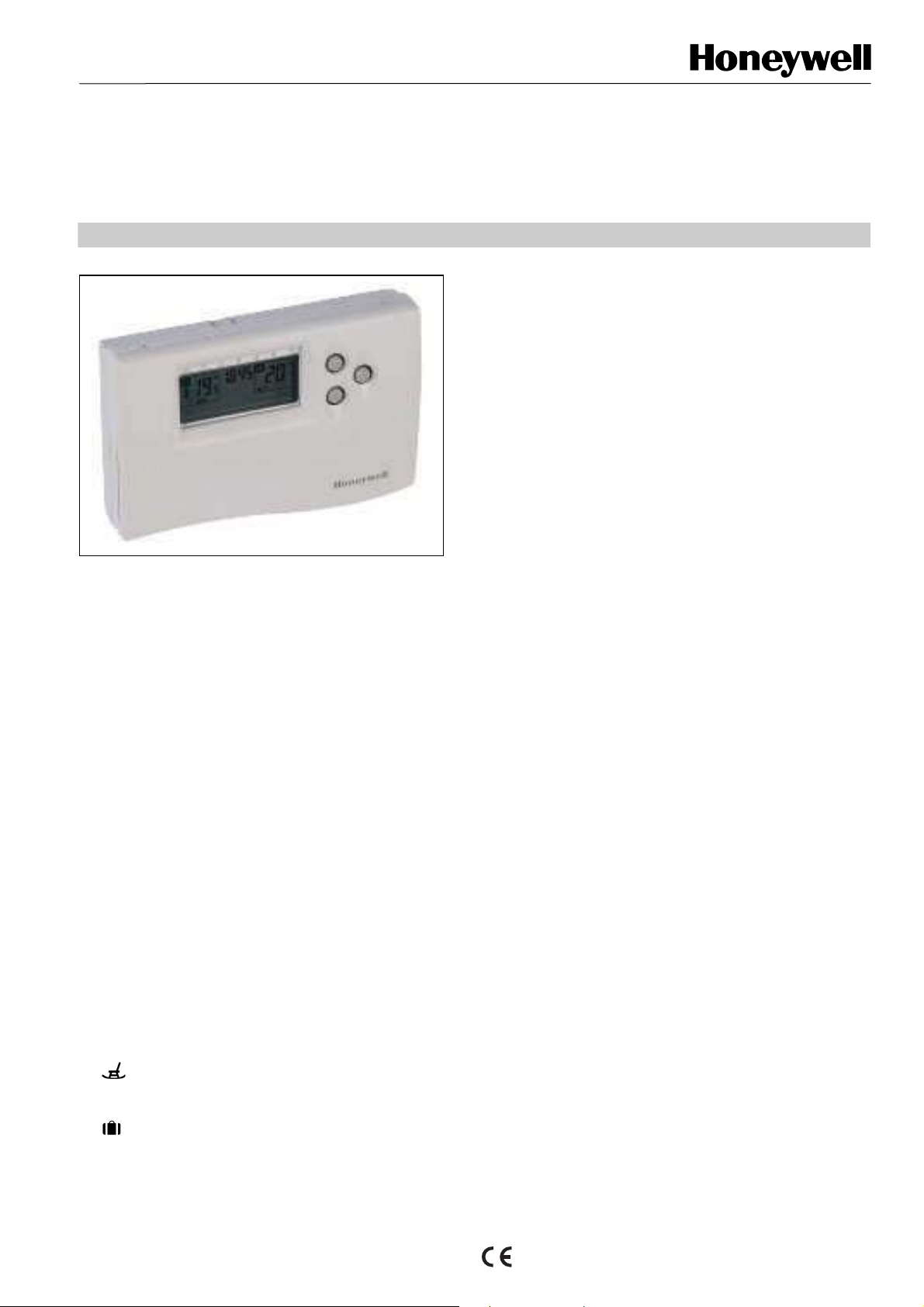
CM67RFMV
WIREFREE CHRONOTHERM
PRODUCT DATA
I
FEATURES
• CM67RF MV can be installed without disrupting your
room décor – no wired connection required between
the room unit and the boiler
• Reliable RF communication utilising 868,3 MHz band
with 1 % duty cycle limit to minimise communication
disturbance
• CM67RF MV can be used to control directly mixing
valves depending on the room setpoint temperature
• Maximum system efficiency and extended boiler life
due to unique zoning system synchronisation
• Up to 4 CM67RF MV can be bound with one HC60NG
for boiler feedback heat on demand
• Suitable for any room décor due to subtle styling
• Easy to program – user friendly interface allowing 7-
day programming to match variety of lifestyles
• Armchair programmed
• Non volatile memory holds the user program
permanently even when batteries being replaced
• Party button to temporarily maintain (or adjust) the
current temperature for 1-23 hours
• Day Off button copies Sunday’s program into
tomorrow or today to allow a rest day program
without having to re-program the CM67RF MV
• Holiday button provides energy savings by
reducing the temperature for 1 to 99 days when
homeowner is on holiday, returning to normal
operation (AUTO or MANUAL) on the day of return.
GENERAL
The CM67RFMV Chronotherm is designed to provide
automatic time and temperature control of heating or cooling
applications. It can be used to control directly mixing valves
for individual zoning control. The Chronrotherm is
communicating with the universal mixing valve controller
HM80 depending on the deviation of the room temperature
and room temperature setpoint the mixing valve will be closed
or opened.
In combination with other CM67RFMV Chronotherms and one
HC60NG receiver it can be used to control the boiler
depending on the heat demand (up to 4 CM67RFMV ).
No wiring to the room unit is required. The installer needs to
wire the universal mixing valve controller HM80 only to the
controlled device mixing valve and mount the room unit in a
suitable location where RF communication is reliable.
The CM67RFMV uses reliable RF communication technology
in the 868,3 MHz band.
The unit is ideal for consumers who want reliable and precise
temperature control from an easy-to-use product.
FEATURES continued
• When used with the table top stan d the room unit can
be positioned anywhere in the room where RF
communication is reliable
• Installer Set-Up Mode allows extra functions to be set
at the discretion of the installer to match the
application :
• Pump after running time
• Mixing valve running time
• Upper / Lower Flow Temperature Limit Adjust
• Upper / Lower Setpoint Limit Adjust
• Forced operation pump
• Forced operation mixing valve
• Temperature offset
• Heat / Cool Operation
• Fail-safe mode for communication loss
• Frost protection is ensured when the slider is in the
OFF position.
• CM67RFMV can be used with Automatic Time Setting
module (Q6667B1007)
EN0H0551GE51 R0905
Page 2
CM 67 RFMV
y
CM67RFMV
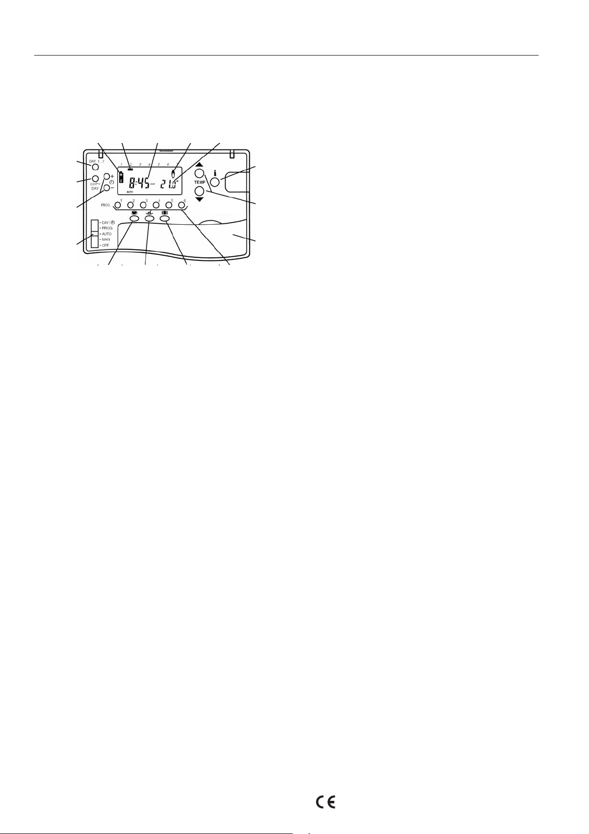
CONTROLS/DISPLAY LAYOUT
Battery Low
Indicator
Day Button
Copy Day
Button
Time Change
Buttons
Setting
Slider
Party Button Day Off Button Holiday Button
Day
Marker
Time
Display
Heat Demand
Indicator
Temperature
Display
Information
Enquir
Temperature
Change
Buttons
=
increase
= decrease
Battery
Compartment
Programming Buttons
Button
SPECIFICATIONS
ELECTRICAL
Room unit power : 2 x 1.5 V IEC LR6 (AA) Alkaline cells
supply
Battery life : 3 years typical
Battery : Program retained in EEPROM
replacement
Receiver power : 230 V AC + 10% - 15%, 50Hz
supply
Switch type : SPDT potential free
Output rating : 24-230 V AC, 10 A resistive, 3 A inductive 0.6
p.f.
Wiring (receiver : Cable terminals for mains and relay wiring for
only) max 2.5 mm
Wire access : from the rear (wall box mounting), right and
bottom
RF Communication
RF operation band : ISM (868.0-868.6) MHz, 1% duty cycle
RF communication : 30 m in a residential building environment
range
RF communication : short, high rate transmissions to minimise air
technology time and avoid collisions
Blocking immunity : Receiver class 2 (ETSI EN300 220-1 version
1.3.1)
RF binding method : Factory pre-bound with the room unit. For
multi-zone application receiver can be bound
to 4 different room units via simple binding
procedure)
ENVIRONMENTAL & STANDARDS
Operating : 0 to 40 °C when relay load < 8 A
temperature : 0 to 30 °C when relay load > 8 A
Shipping & storage : -20 to 55 °C
temperature
Humidity : Humidity range 0 to 90 %, non-condensing
IP class : 30
Meeting the : EN60730-1(1995), EN55014-1(1997),
following EN55014-2(1996), ETSI EN300 220-3(2000),
standards ETSI EN301 489-3(2000)
2
wire
TEMPERATURE CONTROL
Sensing element : 100K (@ 25 oC ) NTC thermistor
TIME SETTING / PROGRAMMING
Time display : 24 hour or 12 hour AM/PM format
Time keeping
accuracy
Program : 7-day with 6 daily time and temperature
Time setting
resolution
Temperature
setting range
Room
Temperature
display range
: Typically better than 10 minutes per
year
level changes
: Time of day - 1 minute
Program – 10 minute steps
o
: Program : 5 to 30
Frost : 5
to 16
: From 0
0.5
o
C or equal to lower limit (5 oC
o
C).
o
C to 40 oC (Display resolution
o
C)
C in 0.5 oC steps
EN0H0551GE51 R0905
Page 3

CM 67 RFMV
APPLICATION A
Mixing Valve Application for UFH without boiler feedback
Mixing Valve Application for UFH without boiler feedback
Mixing Valve Application for UFH without boiler feedback
CM67RFMV with parameter
CM67RFMV with parameter
M67RFMV with parameter
C
ttings
se
ttings
se
ttings
se
mp after runnin g time 0…99 min
Pu
mp after runnin g time 0…99 min
Pu
mp after runnin g time 0…99 min
Pu
ctuator running time 0…240 s
A
ctuator running time 0…240 s
A
ctuator running time 0…240 s
A
in flow tempera ture setpoint 0…50°C
M
in flow tempera ture setpoint 0…50°C
M
in flow tempera ture setpoint 0…50°C
M
x flow temperature setpoint 0…99°C
Ma
x flow temperature setpoint 0…99°C
Ma
x flow temperature setpoint 0…99°C
Ma
CM67RFMV
CM67RFMV
CM67RFMV
Tshe HM80 controls the mixing valve depending on the room temperature
Tshe HM80 controls the mixing valve depending on the room temperature
Tshe HM80 controls the mixing valve depending on the room temperature
etpoint and communicates with the CM67RFMV. In addition the controller
etpoint and communicates with the CM67RFMV. In addition the controller
etpoint and communicates with the CM67RFMV. In addition the controller
as a relay output for pump control and connection for the flow sensor.
h
as a relay output for pump control and connection for the flow sensor.
h
as a relay output for pump control and connection for the flow sensor.
h
t using the flow sensor the mixing valve position is adjusted in accordance with
Withou
t using the flow sensor the mixing valve position is adjusted in accordance with
Withou
t using the flow sensor the mixing valve position is adjusted in accordance with
Withou
he room setpoint t emperature and the actual room temperature.
t
he room setpoint t emperature and the actual room temperature.
t
he room setpoint t emperature and the actual room temperature.
t
f the flow sensor is used the mixing valve position is adjusted in accordance with the
I
f the flow sensor is used the mixing valve position is adjusted in accordance with the
I
f the flow sensor is used the mixing valve position is adjusted in accordance with the
I
alculated flow temperature setpoint and the measured flow temperature. The flow
c
alculated flow temperature setpoint and the measured flow temperature. The flow
c
alculated flow temperature setpoint and the measured flow temperature. The flow
c
emperature setpoint is calculated from the room temperature setpoint and the act ual
t
emperature setpoint is calculated from the room temperature setpoint and the act ual
t
emperature setpoint is calculated from the room temperature setpoint and the act ual
t
m temperature deviation.
roo
m temperature deviation.
roo
m temperature deviation.
roo
APPLICATION B
Set-up specific applications parameters
Enable special features
Establish support for ATS module
Special Features Description Setting
Pump after running time
Mixing valve running time Adjust mixing valve running time (default 150s)
Flow temperature max. Maximum flow temperature limit.
Flow temperature min. Minimum flow temperature limit.
If the mixing valve is closed the pump continuous run for to
the set run time
Flow temperature sensor
Flow temperature sensor
Flow temperature sensor
Flow temperature sensor
T7414C1012 (optional)
T7414C1012 (optional)
T7414C1012 (optional)
T7414C1012 (optional)
HM80
HM80
HM80
HM80
Pump
Pump
Pump
Pump
M
M
M
M
Mixing Valve
Mixing Valve
Mixing Valve
Mixing Valve
0…….99 minutes
0…...240s
0……99°C
0…....50°C
EN0H0551GE51 R0905
Page 4

CM 67 RFMV
Mixing Valve Application for UFH with boiler feedback
Mixing Valve Application for UFH with boiler feedback
CM67RFMV with parameter
CM67RFMV with parameter
settings
settings
Pump after running time 0…99 min
Pump after running time 0…99 min
Actuator running time 0…240 s
Actuator running time 0…240 s
Min flow temperature setpoint 0…50°C
Min flow temperature setpoint 0…50°C
Max flow temperature set point 0…99°C
Max flow temperature set point 0…99°C
CM67RFMV
CM67RFMV
Flow temperature sensor
Flow temperature sensor
T7414C1012 (optional)
T7414C1012 (optional)
HM80
HM80
M
M
Pump
Pump
Mixing Valve
Mixing Valve
HC60NG
HC60NG
R6660D
R6660D
Boiler feedback
Boiler feedback
Boiler
Boiler
Automation and Control Solutions
Honeywell GmbH
Boeblinger Strasse 17
D-71101 Schoenaich
Phone: (49) 7031 63701
Fax: (49) 7031 637493
http://europe.hbc.honeywell.com
Subject to change without notice. Printed in Germany Manufacturing location certified to
EN0H0551GE51 R0905
 Loading...