

Page 1
Honeywell | Cloud Link 4G Modem
Cloud Link 4G Modem User Manual
Mercury Instruments 512 Virginia Drive. Ft. Washington, PA 19034 USA
FD-585 | 1.0 | 2016
Honeywell Process Solutions
Page 2

Copyright 2016 . Honeywell Process Solutions. All rights reserved.
Information in this document is subject to change without notice. The software described in
this document is furnished under a license agreement or non-disclosure agreement. The soft-
ware may be used or copied only in accordance with the terms of those agreements. No part of
this publication may be reproduced, stored in a retrieval system, or transmitted in any form or
any means electronic or mechanical, including photocopying and recording for any purpose
other than the purchaser's personal use without the written permission of Honeywell Process
Solutions.
Mercury Instruments 512 Virginia Drive. Ft. Washington, PA 19034 USA
Page 3

1 General 5
1.1 Cloud Link 4G Modem Overview 6
1.2 Cloud Link 4G Modem Feature Summary 6
2 Safety 7
2.1 Accordance to regulations 8
2.2 Label 9
3 Mechanical Assembly 11
3.1 Device Dimensions 12
3.2 Power options 14
3.3 Antenna Options 15
3.4 Installation Drawing 17
3.5 Field Installation 18
4 Electrical Assembly 19
4.1 Power Supply options 20
4.1.1 Power Port - Battery 21
4.1.1.1 Battery pack drawing 22
4.1.2 Power Port – External Supply 23
4.2 Serial Communication – RS232/485 24
4.3 Pulse Counter 27
4.4 Antenna Interface 28
4.5 Magnetic REED Switch 29
4.6 SIM Card 30
4.7 BLE (Bluetooth Low Energy) 33
4.8 LED Indicators 34
5 Configuring Cloud Link 4G Modem 37
CONTENTS
5.1 Working Modes 38
5.2 Getting started with MasterLink iOS application 39
5.2.1 Login and Registration 39
5.2.2 Adding a New Site 40
5.2.3 Connecting to Existing Site 41
5.3 Bluetooth Pairing with MasterLink iOS application 43
5.3.1 Pairing with Just Works (without passkey) 43
5.3.2 Pairing with Passkey Entry 44
5.4 Item Reference 46
5.5 Device Configuration Over Bluetooth 54
5.5.1 Configuration by Group 54
5.5.2 Configuration by Item 55
Page 4

5.6 Firmware Upgrade 56
5.7 Server Mode 58
5.8 Pulse Counting 59
5.9 Changing the Battery 60
5.10 Factory Reset 61
5.11 Time Sync 62
5.12 Secure Sign On 63
5.12.1 Secure Sign On Over Bluetooth 64
5.12.2 White List 65
5.13 Logs 66
5.13.1 Event Logs 66
5.13.2 Diagnostic Logs 68
5.13.3 Alarm Logs 69
5.13.4 Cellular Logs 71
CONTENTS
Page 5

1 General
This chapter introduces the Cloud Link 4G Modem and also talks about the device fea-
tures.
CHAPTER 1
Page 6

1 General
1.1 Cloud Link 4G Modem Overview
1.1 Cloud Link 4G Modem Overview
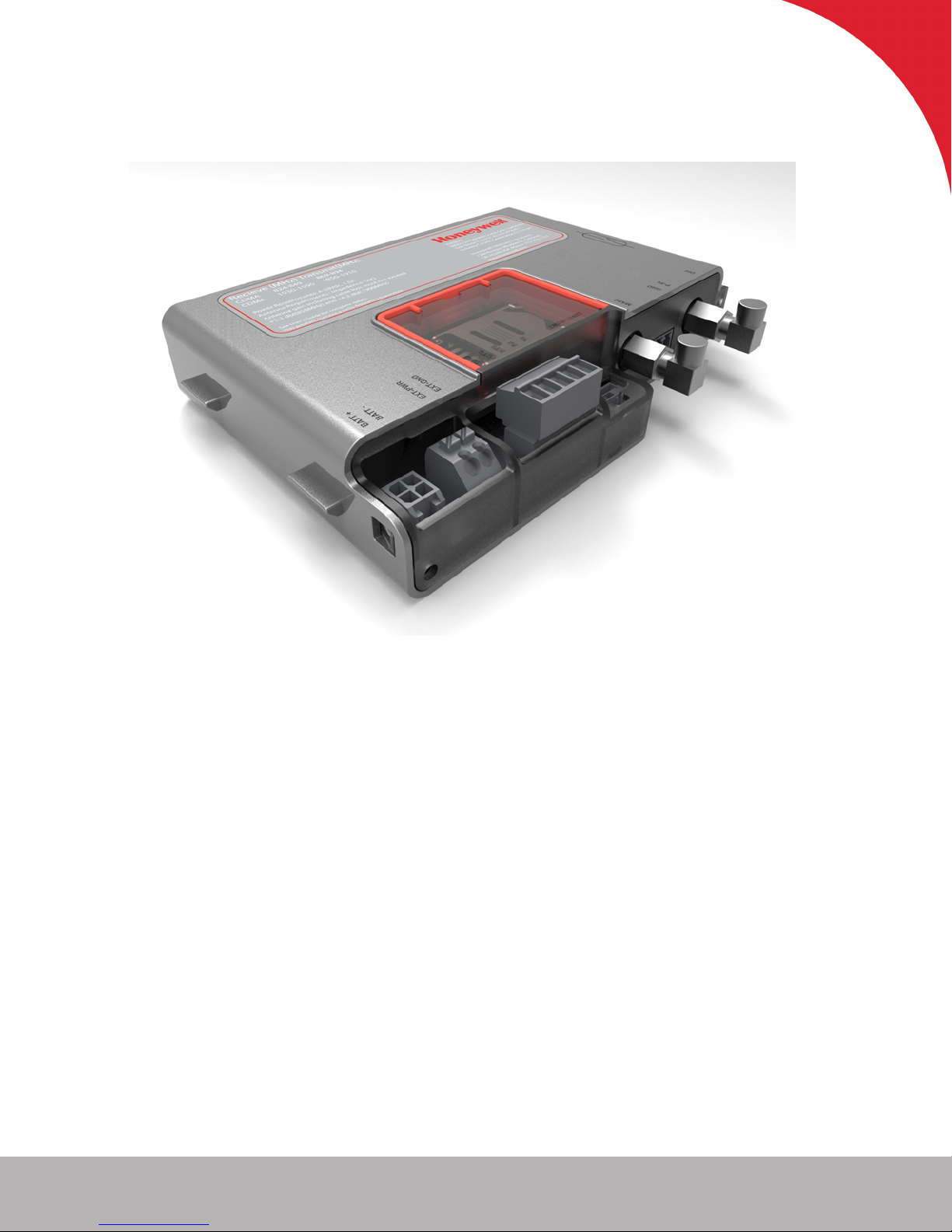
Cloud Link 4G Modem is a cellular radio that can be used as a component in Electronic Volume Cor-
rectors platforms and in wireless platforms. Cloud Link 4G Modem can function as a standalone trans-
parent modem, and can also be included as a component in EC 350 and MiWireless. Cloud Link 4G
Modem can also interface with MasterLink.
1.2 Cloud Link 4G Modem Feature Summary
RS-232 & RS-485
Bluetooth Low Energy V4.0
GSM / GPRS (2G)UMTS / HSPA (3G) LTE (4G)
IPv4
Secure Socket Layer (SSL / TLS 1.2)
Client Mode
Server Mode
Cellular Statistics
Over-the-Air Firmware Configuration Updates
North American Cellular Network Approvals
Alarm-Sensing or Pulse-Counting Input
Built-In magnetic call switch
External power supply (30V max)
Diversity Antenna Connection
Single or Dual 3.6V battery operation
Transparent Modem
Honeywell 2016
6
Page 7

2 Safety
This chapter describes the different safety aspects involved with the Cloud Link 4G
Modem, along with the agency approvals.
CHAPTER 2
Page 8

2 Safety
2.1 Accordance to regulations
2.1 Accordance to regulations
CSA C/US Class I, Division 2, Group A, B, C & D; T4
IEC 61000-6-2
IEC 61000-6-4
CAN/CSA-C22.2 No. 0-M91 General Requirements – Canadian Electrical Code, Part II
C22.2 No. 142-M1987 Process Control Equipment
C22.2 No. 213-15 Non-Incendive Electrical Equipment for Use in Class I, Division 2 Hazardous
Locations
FCC Title 47 CFR sub-part B
IC Canada (ICES-003 Issue 6)
PTCRB (55982)
List of USA and Canada Carriers certification in Progress: Verizon, AT&T, T-Mobile, Rogers, Bell
Mobility
Bluetooth 4.0 (Declaration ID: D031443)
Supporting 3GPP Release 9 LTE, E-UTRA operating bands 2, 4, 5, 13 and 17
ROHS compliant
Operating Temp: -25 °C to +65 °C
Compliance with FCC and IC Rules and Regulations
The integration is limited to fixed or mobile categorized host devices, where a separation dis-
tance between the antenna and any person of min. 20cm can be assured during normal oper-
ating conditions.
For mobile and fixed operation configurations the antenna gain, including cable loss, must not
exceed the limits 1.10 dBd (850 MHz), 5.50 dBi (AWS) and 2.51 dBi (1900 MHz).
Verizon FOTA support:
Cloud Link 4G Modem does not support FOTA upgrade for the cellular module (Gemalto’s PLS8-X).
Honeywell 2016
8
Page 9
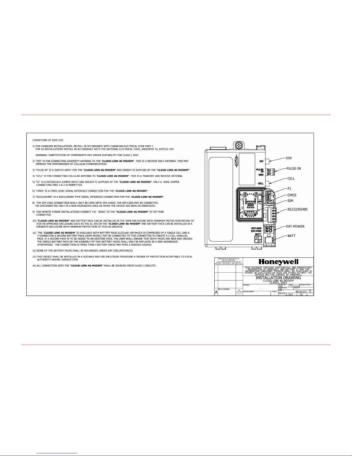
Conditions for safe use
The Cloud Link 4G Modem is available with battery pack 51203165-100 which is comprised of a
single cell and a Y connector. A second battery pack (same model) may be connected to this con-
nector to create a 2 cell parallel pack. If a second pack is to be added to an existing pack, the
user shall ensure that both packs are new and unused. The single battery pack or the assembly
of two battery packs shall only be replaced in a non-hazardous area. The connection of more
than 2 battery packs may pose a serious hazard.
None of the battery packs shall be recharged under any circumstances.
The battery packs shall not be replaced in a hazardous area.
The Cloud Link 4G Modem battery packs shall be housed within an enclosure providing a min-
imum ingress protection level of IP 20.
The SIM card connection shall only be used with SIM cards. The SIM card may be connected or
disconnected only in a non-hazardous area or when the device has been de-energized.
All connections into the Cloud Link 4G Modem shall be sourced from Class 2 circuits.
2 Safety
2.2 Label
This device shall be installed in a suitable end use enclosure providing a degree of protection
acceptable to the local authority having jurisdiction.
Non-Incendive when Installed As Per Drawing 40-6114
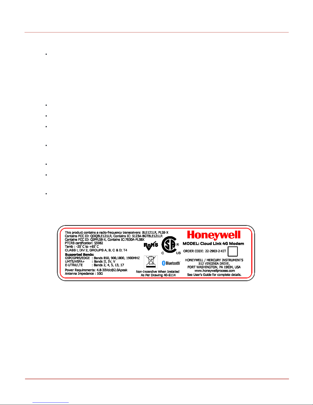
2.2 Label
Figure 2.1 - Cloud Link 4G M odem Label
Honeywell 2016
9
Page 10

This page intentionally left blank to ensure new chapters start on right (odd number) pages.
Page 11

3 Mechanical Assembly
This chapter describes the mechanical assembly of the different components of a Cloud
Link 4G Modem.
CHAPTER 3
Page 12
3 Mechanical Assembly
3.1 Device Dimensions
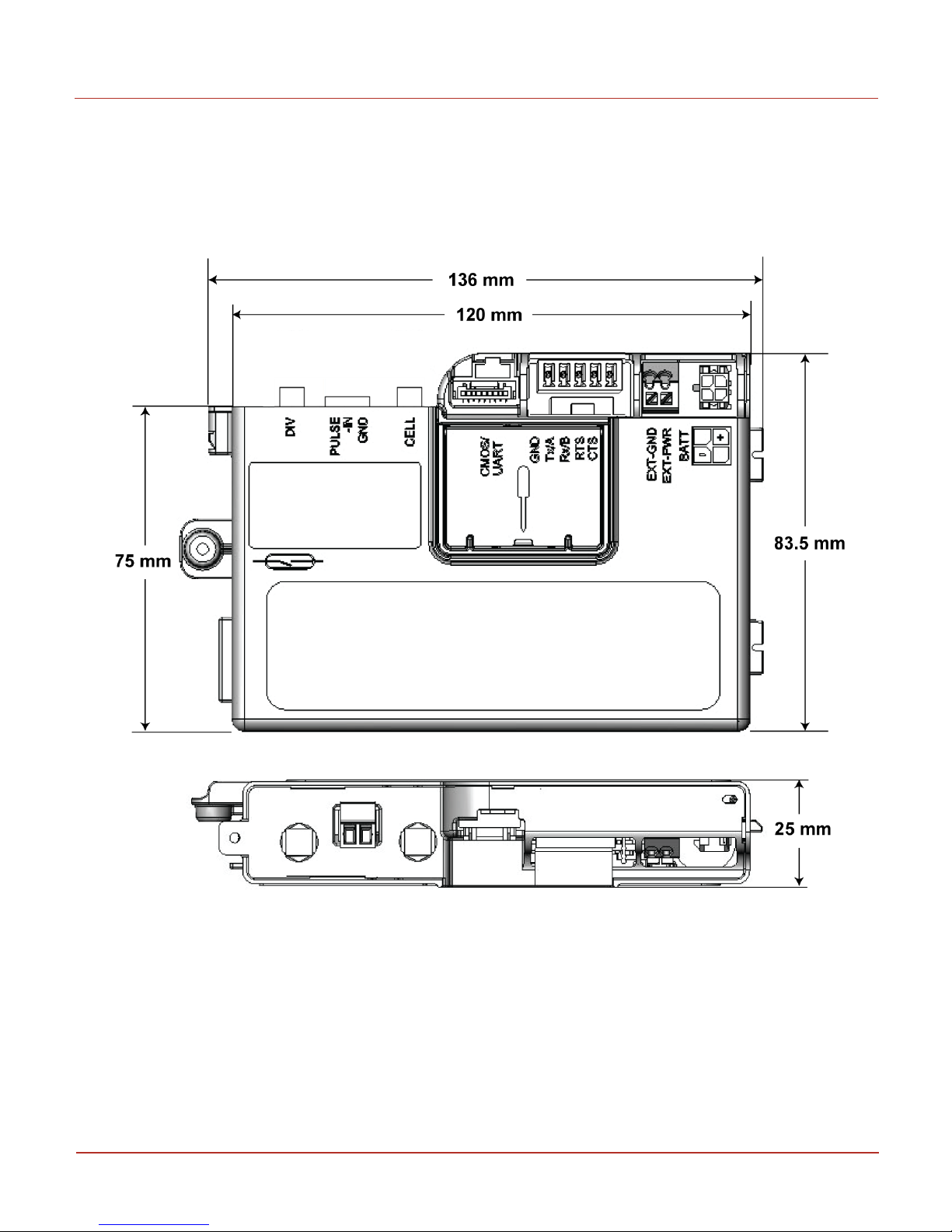
3.1 Device Dimensions
The figure below illustrates the dimensions of a Cloud Link 4G Modem device. (All dimenstions are in
mm)
Honeywell 2016
12
Page 13
3 Mechanical Assembly
3.1 Device Dimensions
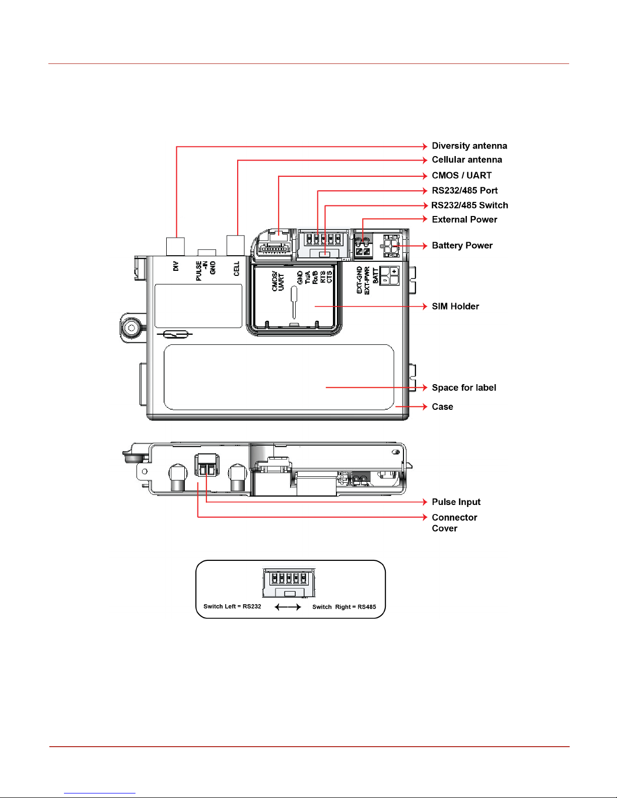
The figure below illustrates the placement of different interfaces available in a Cloud Link 4G Modem
device.
Honeywell 2016
13
Page 14

3 Mechanical Assembly
3.2 Power options
3.2 Power options
The Cloud Link 4G Modem device supports the following power supply options :
1. An optional second lithium D cell to supply power.
2. External DC power with battery backup, typically coming from a 12 V type battery, backed by a
solar charger (Maximum 30 V).
There are two power connectors, one for a primary source up to 30 Vdc, and the other as
backup.
Note: Note: Backup power source is required in case Cloud Link 4G Modem is powered using
external DC supply.
Honeywell 2016
14
Page 15

3 Mechanical Assembly
3.3 Antenna Options
3.3 Antenna Options
The FXUB63 flexible ultra wideband antenna is designed to cover all working frequencies in the 698-3000
MHz spectrum. The antenna has a flexible body with excellent efficiencies on all bands, ground inde-
pendent, with cable and connector for easy installation. The Cloud Link 4G Modem includes 2 FXUB63
antennas - a Diversity antenna and a Cellular antenna.
Cell antenna transmits and receives data; Diversity antenna only receives the signal. Antenna can be
placed inside EVC enclosure or similar enclosure or in cases where signal strength is a concern. External
antenna options are also supported.
Note: The RF cable used can be 20 cm long.
Honeywell 2016
15
Page 16
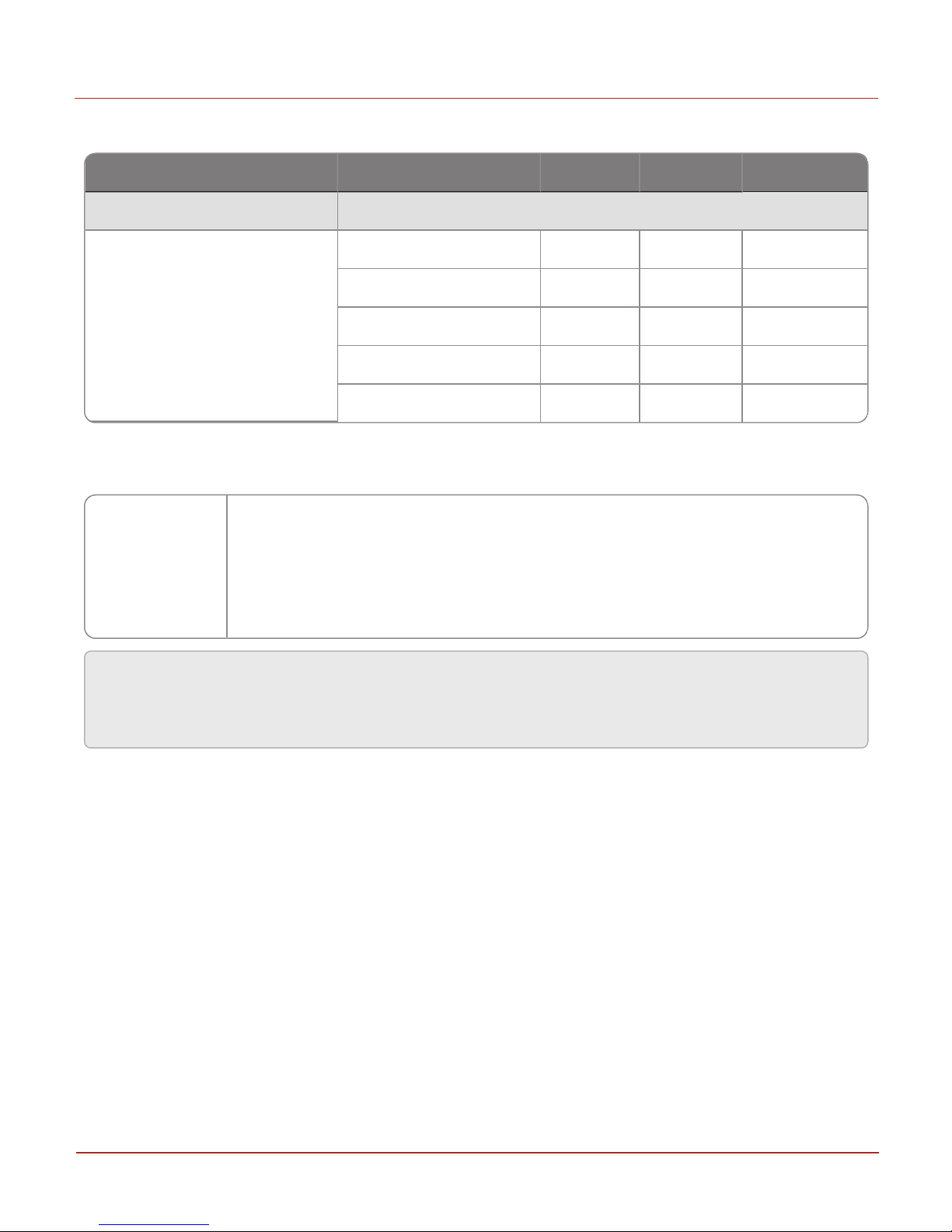
Parameter Conditions Min. Typical Unit
LTE connectivity Band 2, 4, 5, 13 and 17
Receiver Input Sensitivity@ ARP
(ch. bandwidth 5MHz)
LTE 700 Band 17 -97 -102 dBm
LTE 700 Band 13 TBD TBD dBm
LTE 850 Band 5 -98 -104 dBm
LTE AWS Band 4 -100 -103 dBm
LTE 1900 Band 2 -98 -103 dBm
Frequency Bands
PLs8-X:
GSM/GPRS/EDGE: Quad band, 850/900/1800/1900MHz
UMTS/HSPA+: Triple Band, 850 (BdV) / AWS (BdIV) / 1900MHz (BdII)
LTE: Five band, 700 (Bd13) / 700 (Bd17) / 850 (Bd5) / AWS (Bd4) / 1900MHz (Bd2)
3 Mechanical Assembly
3.3 Antenna Options
Receive Sensitivity
Cloud Link 4G Modem supports band 2, band 4 and band 13 for Verizon networks. Cloud Link 4G Modem
supports the following frequency bands for other networks.
Attention: Antennas must be placed away from metallic parts like Batteries, Pressure Transducers,
Grounding plates. Cell & Diversity antenna must not be kept close to avoid self interference. It is
recommended to keep one antenna vertical and other antenna horizontal.
Honeywell 2016
16
Page 17
3 Mechanical A ssembly
3.4 Installation Drawing
Honeywell 2016
17
3.4 Installation Drawing
Page 18
3 Mechanical Assembly
3.5 Field Installation
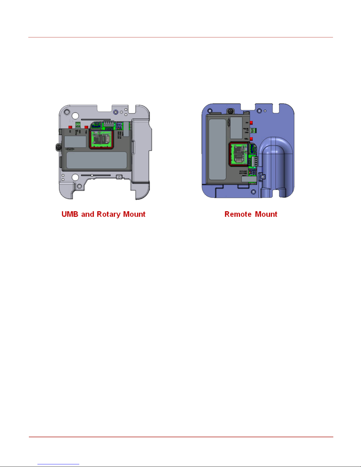
3.5 Field Installation
Cloud Link 4G Modem can be installed in an EC 350 Electronic Volume Corrector device using a mount-
ing bracket as shown in the figure below. Position the 2 tabs of the Cloud Link 4G Modem case in the
mounting bracket and use 6-32 screws to fix the device with the mounting bracket.
Honeywell 2016
18
Page 19

4 Electrical Assembly
This chapter describes assembly of the different electrical components of a Cloud Link
4G Modem.
CHAPTER 4
Page 20
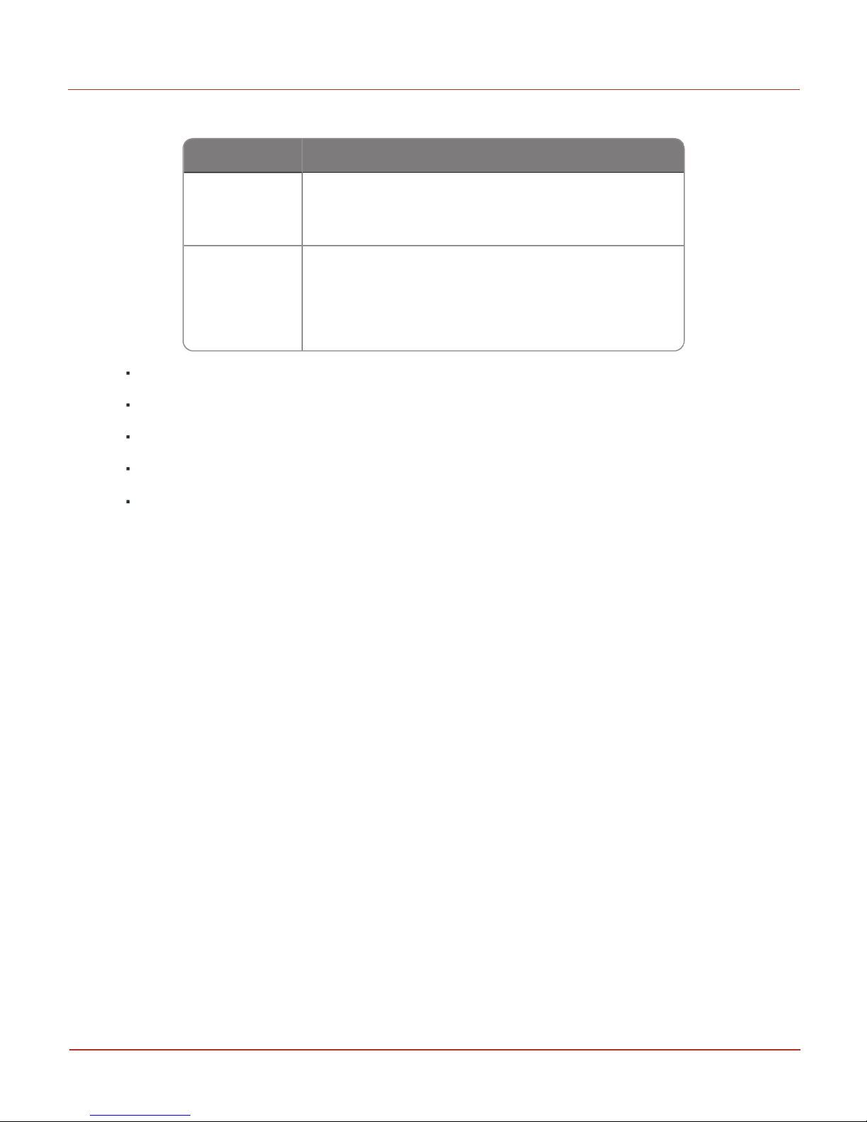
Voltage Range Type
3.0V to 3.6V
(Li-SOCI2) D-Cell + HLC
(For pulse power)
4.8V to 30V 1. External Power supply
(Ex: Solar power)
2. Alkaline Battery pack with external super capacitor.
4 Electrical Assembly
4.1 Power Supp ly options
4.1 Power Supply options
Humidity: Max 95% rH, non-condensing
Peak current during transmission 3A @ 3.8V
Duty cycle (GSM)during communication 0.577ms every 4.6ms.
Operating voltage 4.8V to 30V
Dynamic Response & Low Ripple
Honeywell 2016
20
Page 21

4 Electrical Assembly
Data Value
Voltage 3.6V (Max 3.9V)
4.1 Power Supp ly options
4.1.1 Power Port - Battery
Cloud Link 4G Modem battery connector connects the device to a single Lithium D-Cell with a voltage rat-
ing of 3.6V. Below are the battery specifications recommended to be used for Cloud Link 4G Modem.
Battery Part Number: 51203165-100
Caution: Do not use a Sierra Wireless power supply as it may damage the Cloud Link 4G Modem
device.
Honeywell 2016
21
Page 22
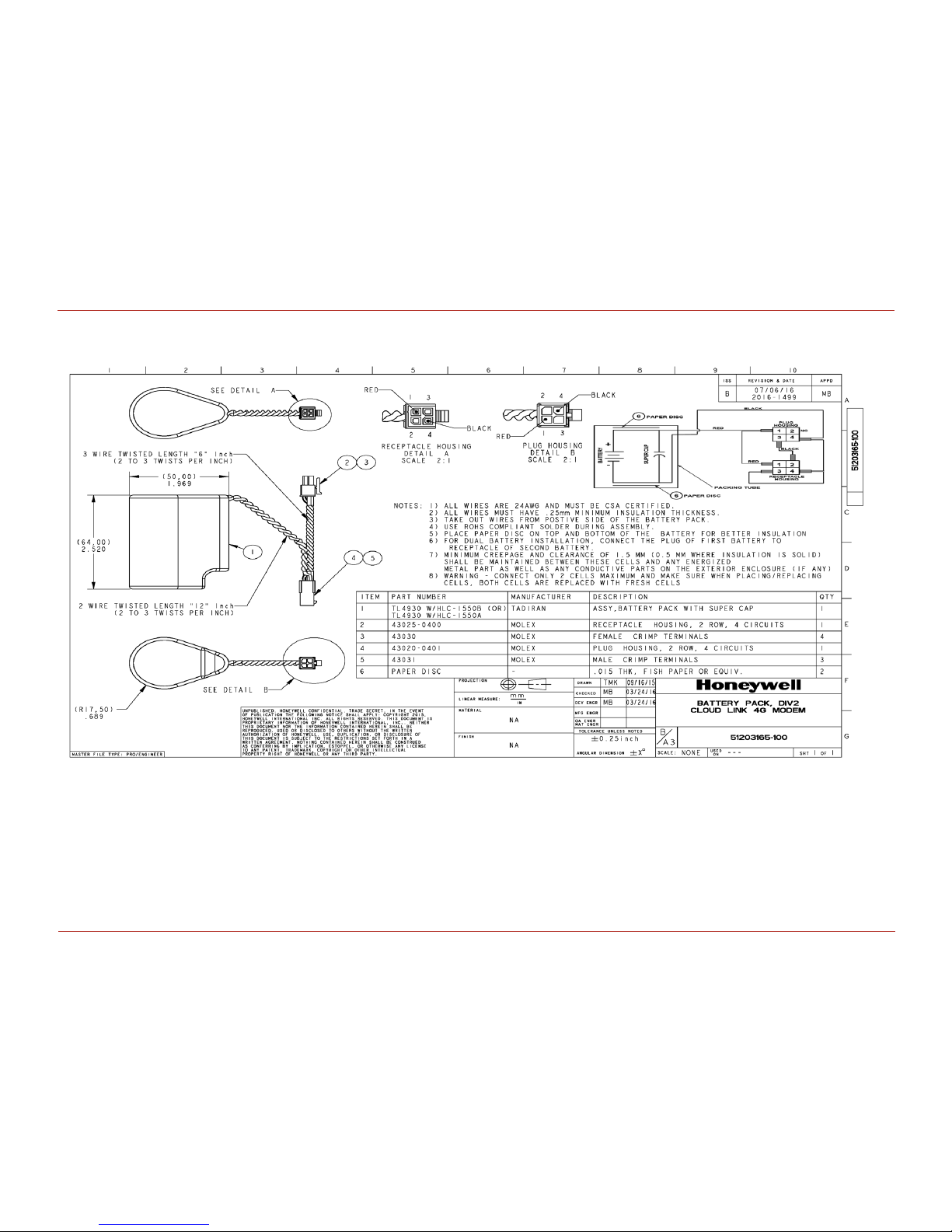
4.1.1.1 Battery pack drawing
4 Electrical Assembly
4.1 Power Supp ly options
Honeywell 2016
22
Page 23

4.1.2 Power Port – External Supply
Data Value
Operating Voltage 4.8V to 30V
Average Current 1A
Peak Current 2A
Cloud Link 4G Modem North America supports external power supply.
Pin Description:
EXT-GND: Negative (-) terminal/Return of the external supply
EXT-PWR: Positive (+) terminal of the external supply
4 Electrical Assembly
4.1 Power Supp ly options
Connector on Cloud Link 4G Modem:
MPN: 250-102, MFR: WAGO: Spring Loaded 2-pin Terminal Block
Honeywell 2016
23
Page 24

Pin# Name Description I/O Voltage Levels
1 Gnd Ground Ground
2 RS232 Tx (or)
RS485 A
RS232 Mode: Transmit Line O
+/- 3.7V (Min)
+/-4V (Typ)
RS485 Mode: Non-inverting Driver
Output and Non-inverting Receiver
Input
I/O Diff Driver Output:
2.7V (typ)
3 RS232 Rx (or)
RS485 B
RS232 Mode: Receive Line I +/- 10V (max)
RS485 Mode: Inverting Driver Output
and Inverting Receiver Input
I/O Diff Driver Output:
2.7V (typ)
4 RS232 RTS RS232 Mode: Request To Send (RTS) O +/- 3.7V (Min)
RS485 Mode: NC (No Connection)
5 RS232 CTS RS232 Mode: Clear To Send (CTS) I +/- 10V (max)
RS485 Mode: NC (No Connection)
4 Electrical Assembly
4.2 Serial Communication – RS232/485
4.2 Serial Communication – RS232/485
Cloud Link 4G Modem as a transparent cellular modem supports traditional RS232/RS485 interface (only
one at a time). You can select either RS232 or RS485 by adjusting the position of the switch provided on
the device.
Honeywell 2016
24
Page 25

4 Electrical Assembly
4.2 Serial Communication – RS232/485
Note: While switching between RS232 or RS485, you must change firmware configuration using the
appropriate item code. The RS485 cable supports a baud rate range from 9600 to 57600 bps. Max-
imum baud rate for RS232 interface is 115200 bps.
Warning: Older RS232 standards have a voltage level of +/- 18V. Using this voltage level can damage
the Cloud Link 4G Modem device.
Note: RUID must be configured before using BLE communication. Configuration must be done using
serial commincation.
To keep power consumption low when not in communication, both transmitters (Tx & RTS) are to be
turned off and RS485 will be in Receiving Mode in Cloud Link 4G Modem. To reduce power consumption,
it is recommended to do same in the EVC or any other device where Cloud Link 4G Modem is interfaced.
Cloud Link 4G Modem Controller can wake-up from deep sleep via Rx Line or CTS line of RS232 Interface
(or) Rx line of RS485 interface.
MPN: 0395011005
MFR: Molex
Description: 5-Pin Terminal Block Header
MPN: 0395000005
MFR: Molex
Description: 5-Pin Terminal Block Plug
Cable for RS232:
Cloud Link 4G Modem supports up to 30m (100ft) long cable for RS232 interface with shielded cable.
Shield of RS232 cable must be terminated to Earth at one point to make interface immune to EMI/EMC.
Recommended RS232 Cable:
MPN: 9941 060100
MFR: Belden
Description: 5-Conductor Low Capacitance Shielded Cable of Length 30m (100ft).
Honeywell 2016
25
Page 26

4 Electrical Assembly
4.2 Serial Communication – RS232/485
Cable for RS485:
Cloud Link 4G Modem supports up to 30m (100ft) long cable for RS485 interface at a baud rate of
9600bps with Shielded Cable. Shield of RS485 cable must be terminated to Earth at one point to make
interface immune to EMI/EMC.
Recommended RS485 Cable:
MPN: 8332 060100
MFR: Belden
Description: 2-Pair Low Capacitance Shielded Cable of Length 30m (100ft).
Honeywell 2016
26
Page 27

4 Electrical Assembly
4.3 Pulse Counter
4.3 Pulse Counter
Cloud Link 4G Modem supports 1-channel pulse-counting input up to 10 pulses per second with a min-
imum pulse width of 25 mS; It is to provide additional redundancy on the UMB pulse input front end. A
pulse input from the UMB is wired to this additional pulse input. The EVC will read the pulse counter
information recorded in the Cloud Link 4G Modem using AT commands and compare it with its own pulse
accumulation register and raise alarm if any mismatch in accumulation. Pull-up resistor in Cloud Link
4G Modem can drive ~30uA of wetting current.
The pulse counter in Cloud Link 4G Modem is not MID/MC certified, cannot be used for billing.
Connector Details:
MPN: (39512-1002)
MFR: Molex
Honeywell 2016
27
Page 28

4 Electrical Assembly
4.4 Antenna Interface
4.4 Antenna Interface
Connector Specs:
MPN: 73251-1150
MFR: Molex
Description: Edge Mounted SMA connector
Recommended Antenna:
HPN: 51508416-100
Description: Octa-Band LTE Antenna (Bands 700/750/850/900/1800/1900/2100/2700 MHz)
Honeywell 2016
28
Page 29

4 Electrical Assembly
4.5 Magnetic REED Switch
4.5 Magnetic REED Switch
Magnetic Reed Switch in Cloud Link 4G Modem enables field technician to swipe a hand-held magnet
near Reed switch in order to initiate a call.
Honeywell 2016
29
Page 30

4 Electrical Assembly
4.6 SIM Card
4.6 SIM Card
This connector on Cloud Link 4G Modem holds the cellular radio Standard SIM card. Cloud Link 4G
Modem supports both 1.8V (Class C) and 3.0V (Class B) version SIM cards.
Lift the SIM cover to place the SIM card. Slide back the internal holder and flip it open.
Insert a SIM card in the slot provided and close the cover.
Honeywell 2016
30
Page 31

Procedure to switch from Non-Verizon to Verizon mode
Item Number Description Value
3071 Verizonenable
1
0 = disable
1 = enable
3021 ModemIPType
2
0 = IPV4
1= IPV6
2 = IPV4V6
3016 Fetch Radio Parameters
1
0 = Disable
1 = Enable
3022 Packet service Connection Command ATD*99***3#
3064 Manual APN Enable
1 (default)
0= disable
1= enable
3023 Access point name
Configure the following item numbers:
4 Electrical Assembly
4.6 SIM Card
Note: If you enable 3064, then you need to manually configure 3023 based on the regional access
point name. If 3064 is disabled, then then 3023 is automatically populated.
Diconnect the Cloud Link 4G Modem, install the SIM card, and then perform a facroty reset.
Honeywell 2016
31
Page 32

Item Number Description Value
3071 Verizonenable
0
0 = disable
1 = enable
3021 ModemIPType
0
0 = IPV4
1= IPV6
2 = IPV4V6
3016 Fetch Radio Parameters
1
0 = Disable
1 = Enable
3022 Packet service Connection Command ATD*99#
3023 Access point name
4 Electrical Assembly
4.6 SIM Card
Procedure to switch from Verizon to Non-Verizon mode(AT&T,Airtel,Vodafone etc)
Configure the following item numbers:
Diconnect the Cloud Link 4G Modem, install the SIM card, and then perform a facroty reset.
Honeywell 2016
32
Page 33

4 Electrical Assembly
4.7 BLE (Bluetooth Low Energy)
4.7 BLE (Bluetooth Low Energy)
Cloud Link 4G Modem supports Bluetooth Low Energy (BLE) for local communications up to 30m (100ft)
(Line of Sight). The Max transmit power from BLE is +8dBm and receiver sensitivity of -98dBm. The
antenna of BLE is inside Cloud Link 4G Modem, no provision for external antenna is given for BLE.
In order to connect a Cloud Link 4G Modem with MasterLink iOS app, you need to perform a bluetooth
pairing first. Cloud Link 4G Modem supports two types of paring methods
Just Works (no EVC dependency)
Passkey entry (only with EC 350)
Honeywell 2016
33
Page 34

Call establised High Speed LED blink (8 blinks per second)
Call establishment in progress Medium speed LED blink (2 blinks per second)
Call establishment fail Low speed LED blink (1 blink per second)
No Network connection LED off
RSSI excellent 5 blinks per second
RSSI good 2 blinks per second
RSSI fair 1 blink every second
RSSI poor 1 blink every 2 seconds
No signal 1 blink every 5 seconds
no RSSI LED OFF
4 Electrical Assembly
4.8 LED Indicators
4.8 LED Indicators
Note: LED functionality works only when the magnetic switch is enabled
LED 1
LED 2
Honeywell 2016
34
Page 35

LED OFF
LED 3 LED 4 LED 5
LED ON
LED 3 LED 4 LED 5
Number of blinks
All LEDs blink at once Separator
1 blink 1 blink 1 blink Low Super Capacitor voltage
1 blink 1 blink 2 blinks
External OTA Firmware upgrade flash
memory Fault
1 blink 1 blink 3 blinks BLE UART communication fail
1 blink 2 blinks 1 blink BLE MAC address not configured
1 blink 2 blinks 2 blinks Modem UART communication fail
1 blink 2 blinks 3 blinks Config data checksum error
1 blink 3 blinks 1 blink IP Address or port # not configured
1 blink 3 blinks 2 blinks Security Certificate Error
1 blink 3 blinks 3 blinks Low Battery Capacity Indication
2 blinks 2 blinks 1 blink External Data flash memory Fault
2 blinks 2 blinks 2 blinks Network comm fail
4 Electrical Assembly
4.8 LED Indicators
Honeywell 2016
35
Page 36

2 blinks 2 blinks 3 blinks SIM Card Error
All LEDs blink three times
Cloud Link 4G Modem Microcontroller
power cycle occurred
All LEDs blink two times
A condition occurred that caused the pro-
gram to abort and restart, indicating a
possible problem with the Cloud Links
internal circuitry or program
4 Electrical Assembly
4.8 LED Indicators
Note: LED errors will remain active for 15 minutes. They will blink only when an emergency call is
activated.
Honeywell 2016
36
Page 37

5 Configuring Cloud Link 4G Modem
This chapter describes the configuration of a Cloud Link 4G Modem device using the
MasterLink iOS application.
CHAPTER 5
Page 38

5 Configuring Cloud Link 4G Modem
5.1 Working Modes
5.1 Working Modes
The Cloud Link 4G Modem has 2 operating modes:
1. Standalone mode: where the modem functions as an independent device
2. Integrated mode: where the modem is connected and used with an EVC device.
Honeywell 2016
38
Page 39

5 Configuring Cloud Link 4G Modem
5.2 Getting started with MasterLink iOS application
5.2 Getting started with MasterLink iOS application
MasterLink iOS application is available on the iStore. For more information on installing and getting star-
ted with the MasterLink iOS application please refer to MasterLink help from the Honeywell Process Web-
site (https://www.honeywellprocess.com).
5.2.1 Login and Registration
After you have installed the MasterLink iOS application, you need a valid license key. Your company's site
administrator can generate a license file and a user-name that is sent to you in an e-mail.. From the e-
mail, you can open the license file in MasterLink App. You can then use your user-name and password to
register.
1. Tap and hold / or long-press the attachment 2. Select 'Copy to MasterLink' and open the license file
3. Register with your credentials 4. login with your credentials.
Honeywell 2016
39
Page 40

5 Configuring Cloud Link 4G Modem
5.2 Getting started with MasterLink iOS application
5.2.2 Adding a New Site
1. Select Add / Pair Site 2. Select device from the list 3. Enter the Site / device details
4. Site added successfully 5. Dashboard appears
Honeywell 2016
40
Page 41

5 Configuring Cloud Link 4G Modem
5.2 Getting started with MasterLink iOS application
Attention: SiteID 1 or SiteID 2 must be a non-zero value. If either of them has a value equal to zero,
then you must reconfigure it to a non-zero value using MasterLink desktop application connected
using serial interface.
5.2.3 Connecting to Existing Site
1. Select Add / Pair Site 2. Select device from the list
3. Enter the Site / device details
Honeywell 2016
41
Page 42

5 Configuring Cloud Link 4G Modem
5.2 Getting started with MasterLink iOS application
MasterLink automatically connects to an existing site if the instrument is authorized to connect auto-
matically. If there are multiple sites in the vicinity, then you will be prompted to select a site.
Warning: Deleting an existing site does not remove the device pair settings on the mobile device.
Honeywell 2016
42
Page 43

5 Configuring Cloud Link 4G Modem
5.3 Bluetooth Pairing with MasterLink iOS application
5.3 Bluetooth Pairing with MasterLink iOS application
Every Cloud Link 4G Modem device has a unique IMEI and RUID numbers. It is recommended to keep a
note of these numbers as they can be used for identifying the device. RUIDs are used to used to identify a
device using MasterLink desktop application or using PowerSpring.
5.3.1 Pairing with Just Works (without passkey)
1. Select Add / Pair Site 2. Select Cloud Link device from the list
3. Enter the Site / device details 4. Tap Pair to complete the pairing process
Honeywell 2016
43
Page 44

5 Configuring Cloud Link 4G Modem
5.3 Bluetooth Pairing with MasterLink iOS application
5.3.2 Pairing with Passkey Entry
Passkey entry bluetooth pairing works only when the Cloud Link 4G Modem is used in integrated mode.
Here's a high level overview of how passkey entry bluetooth pairing works.
Honeywell 2016
44
Page 45

To pair using passkey:
1. Select Add / Pair Site 2. Select Cloud Link device from the list
5 Configuring Cloud Link 4G Modem
5.3 Bluetooth Pairing with MasterLink iOS application
3. Enter the Site / device details
Note: The passkey must be entered within 40 seconds. The passkey is valid for 40 seconds after which
it expires. If the passkey expires, you need to obtain a new passkey, and start all over.
Honeywell 2016
4. Enter the passkey obtained from the EVC and then
tap Pair.
45
Page 46

ITEM Number Parameter Parameter Description
3002
Cloud Link 4G Modem Serial
Number
Cloud Link 4G Modem Serial Number
3003
Cloud Link 4G Modem Manufacturing Date DD:MM:YYYY:
Cloud Link 4G Modem Manufactuting data
3004 Radio IMIE number Radio identification number
3005 Change Battery
Reset Battery flag clears previously charge consumed data
3006
Advance Low Battery Indication (in days)
Advance Low Battery Indication (in days): Maximum allowed is 255 days and Min allowed is 15
3007 Battery Type
SINGLE_BATTERY_PACK,DUAL_BATTERY_
PACK,QUAD_BATTERY_PACK,ONE_BATT_ONE_SC_
SEPARATE,EXT_PS_SINGLE_BATT_PACK,EXT_PS_
DUAL_BATT_PACK,EXT_PS_ONLY,NO_SUFFICIENT_
SUPPLY
3008 Battery Charge Capacity Battery Charge Capacity: is based on battery type
3009
Super Cap Low voltage to
drop the call
Super cap voltage reading
3010
Battery Voltage Critically low
Threshold
Battery critically low Threshold value
3011 Available % battery life Percentage battery life
3012
Super Cap Charge Availabilty
(in sec)
Super cap voltage in seconds
3013 Battery Voltage Battery voltage
3014 Supercap Voltage Super cap voltage
3015 Battery Charge Consumed Battery Charge Consumed
3016 Fetch radio parameters 0 - Disable 1 - Enable
3017 SSL enable / Disable 0 - Disable 1 - Enable
Security - keys
Security Signed Certificate
Security - CA Certificate
3018 IPSec enable / disable 0 - Disable 1 - Enable
Security - keys
Security Signed Certificate
Security - CA Certificate
User Log in ID User Log in ID: admin
5 Configuring Cloud Link 4G Modem
5.4 Item Reference
5.4 Item Reference
Honeywell 2016
46
Page 47

ITEM Number Parameter Parameter Description
User Log in Password Password: Default : 123456
User Log in ID User Log in ID: admin
User Log in Password Password: Default : 123456
3019 IP Security Cert Expiry Status 0 - Valid 1 -Expired
3020
SSL Security Cert Expiry
Status
0 - Valid 1 -Expired
3021
Mobile or Simple Internet Protocol
0 = Simple Internet Protocol (SIP)
1 = Mobile Internet Protocol (MIP)
3022
Packet Service Connection
Command
This command initiates a packet (internet) connection This can be different for different cellular
providers, but generally the universally-accepted
string is"ATD*99#"
3023 Access Point Name
This is the name of the gateway to the service provider’s internet service. Examples: m2m@T-Mobile.com or isp.cingular
3024 PAP / CHAP Enable
0 = None
1= PAP only
2 = CHAP only
3 = CHAP first and then PAP as a fallback if CHAP
fails.
3025 PAP / CHAP User Nam
3026 PAP / CHAP Pass Word
3027 SIM PIN Number
A numeric string (ex: “54311”) that protects the
SIM card from being used by unauthorized persons.
3028 Cellular Session Timeout 10 sec - 300 sec
3029 SIM Number
3030 Mobile Directory Number
3031 Carrier Name Mobile Carrier name
3032
Internet Protocol Version 4 or
6 (IPv4 or IPv6)
0 = IPv4
1 = IPv6
3033 Source Port Starting Number
3034 Source Port Ending Number
5 Configuring Cloud Link 4G Modem
5.4 Item Reference
Honeywell 2016
47
Page 48

ITEM Number Parameter Parameter Description
3035
Maximum TCP/IP packet size
This defines the maximum data portion of the
TCP/IP packet, which is usually referred to as the
Maximum Segment Size, or MSS. Maximum is
65535 bytes. Legacy Ethernet v2 segment sizes
were limited to about 1460 bytes.
3036 DNS or IP address
This parameter is to select IP address / DNS name
0- IP address
1- DNS
3037
Primary Destination IP
Address (Client Mode) (Can
be IPv4 or IPv6 address
ASCII form size based on IPv4 or IPv6 address
3038
Primary Destination Port
Number (Client Mode).
Destination port number
3039
Alternate Destination IP
Address (Client Mode)
ASCII form size based on IPv4 or IPv6 address
3040
Alternate Destination Port
Number (Client Mode)
Alternate destination port number
3041
Domain Name Server (DNS)
#1
URL of DNS1
3042
Domain Name Server (DNS)
#2
URL of DNS2
3043
Domain Name Server (DNS)
#3
URL of DNS3
3044
Server Mode Friends (White)
List Enable
0 - Disable
1 - Enable
3045-3054
Server Mode Friends (White)
List(10 IP adress)
Server White list IP addresses 1 - 10
3055 Device Wakeup time Device wakeup time after receiving AT commands
3056 Number of total Items Total number of Cloud Link 4G Modem item codes
3057 MI session timeout
BLE session timeout for both Cloud Link 4G
Modem & EVC connection
3058
Last call / Known Signal
StrengthI
Last call known signal strength
3059
Last Known Source IP
Address
Last call IP address
3060 Last Known Source Port Last call IP Port
3061 Modem server timeout Server mode timeout
5 Configuring Cloud Link 4G Modem
5.4 Item Reference
Honeywell 2016
48
Page 49

ITEM Number Parameter Parameter Description
3062 Modem Firmware Version
3063 Radio Modem model
3064
Select communication port to
EVC
3065
RS-232 / RS-485 Serial Port
Baud Rate
3066 CMOS Serial Port Baud Rate
3067
RS-232 Serial Port Flow Control
3068
CMOS Serial Port Flow Control
3069 BLE Baud Enable
3070
Include Baud in CONNECT
Message
3071 Always RING Port
3072
Use Non-Verbose (Numeric)
Response Codes
3073
Serial Port Delay Before Sending Packet
3075 RS485 enable
3076 BLE MAC Address
3077 BLE Device Name
3078
Advertisement interval(in
msec)
3079 BLE Module Status
3080 BLE firmware version
3081 BLE stack versionversion
3082 BLE forget all bonds
3083 BLE host White List Enable 0 - Disable 1 - Enable
3084 BLE Last RSSI
3085 BLE Security type
1-Just works
2- Passkey entry
3086-3093 BLE white list
3112 BLE conn interval Advertisement interval max : data value in mSec
5 Configuring Cloud Link 4G Modem
5.4 Item Reference
Honeywell 2016
49
Page 50

ITEM Number Parameter Parameter Description
3094 Cloud Link 4G Modem Mode
Integrated Mode - 0
Standalone Mode - 1
3095 Remote Unit ID (RUID) Default Value : 000001
3096
Running / Existing Firmware
Version
Cloud Link 4G Modem firmware revision
3097
Running Firmware CRC checksum
Cloud Link 4G Modem firmware checksum
3098
Down Loading Firmware Version
3099
Firmware upgrade max
packet size
3100
Firmware image max size
allowed
3101
Coordinated Universal Time
(UTC)
When the Cloud Link 4G Modem receives a time
and date, it is relative to Coordinated Universal
Time (UTC) which is essentially the same thing as
Greenwich Mean Time (GMT).
3102 Date format type
0 = MM_DD_YY
1 = DD_MM_YY
2 = YY_MM_DD
3103
Cloud Link 4G Modem Bootloader version
3104
Cloud Link 4G Modem Bootloader CRC
3105
Immediate Call on Low-Battery Condition Enable
3106
Immediate Call on Alarm Active Enable
3107
Immediate call on for wrong
login failure
3108 Date
3109 Time
3110 Server mode IP address
3111 Server mode IP port number
3113 Pulse count
3114
Cloud Link 4G Modem board
temperature
5 Configuring Cloud Link 4G Modem
5.4 Item Reference
Honeywell 2016
50
Page 51

ITEM Number Parameter Parameter Description
3115
Cloud Link 4G Modem Configuration Change Event
3116
Cloud Link 4G Modem Firmware Upgrade Event
3117
Cloud Link 4G Modem Password Change Event
Password credential change
3118
Cloud Link 4G Modem POR
counter
Cloud Link 4G Modem power on reset count Event
3119 Login Failure Event Cloud Link 4G Modem login failure Event
3120 Low Battery Alarm Event
0 - Not Active
1 - Active
3121
Emergency Callin Alarm
Event
0 - Not Active
1 - Active
3122 BLE transmit power BLE transmit power
3123 BLE enable BLE enable
3124 Last call Cellular service Last call Cellular service
3125 Last call cellid Last call Cellular ID
3126 Last cal Loc ID Last call location identifier
3127 Last cal RSCP Last call RSCP(3G)
3128 Last cal RSRQ Last cal RSRQ(4G)
3129 Last cal MCC Last cal MCC
3130 Last cal RSRQ Last cal RSRQ
3131 Last cal Physical cell id Last call physical cell id
3132 Last call Cellular RSRP Last call Cellular RSRP
3133 Last call Cellular TAC Last call cellular TAC
3134 Last call duration Lats successful call duration
3135 Last call status Last call status
3136 Pulse count enable Pulse count enable
3137 Restore/Reset/Clear logs Misc Item Action Input
3138 Modem server timeout
3139 Remote Unit ID 2 (RUID)
3140 Temperature units
3141 BLE number of bonds
5 Configuring Cloud Link 4G Modem
5.4 Item Reference
Honeywell 2016
51
Page 52

ITEM Number Parameter Parameter Description
3142 MIWireless Enable
3143 BLE start time
3144 BLE stop time
3425 Factory test access number Access code to enter into factory mode
3426 Factory test mode status
3427 Factory test item number
FT_MODEM_POWER_ON= 1,
FT_MODEM_POWER_OFF= 2,
FT_SIM_TEST= 3,
FT_SRAM_TEST= 4,
FT_DATA_FLASH= 5,
FT_OTA_FLASH= 6,
FT_SUPER_CAP_VOLTAGE = 7,
FT_BATTERY_VOLTAGE= 8,
FT_EXT_POWER_VOLTAGE = 9,
FT_MAGNETIC_SWITCH= 10,
FT_TEMPERATURE= 11,
FT_BLE_MODULE= 12,
FT_LED_TEST= 13,
FT_SLEEP_TEST= 14,
FT_MET_JUMPER= 16,
3428 Modem power ON Result
3429 Modem power OFF Result
3430 SIM test Result
3431 BLE test Result
3433 Test data flash Result
3434 Test OTA flash Result
3435 Test SRAM
3436 Magnetic switch status
3437 Metrology jumper status
5 Configuring Cloud Link 4G Modem
5.4 Item Reference
Honeywell 2016
52
Page 53

5 Configuring Cloud Link 4G Modem
ITEM Number Parameter Parameter Description
3148
Cloud Link 4G Modem model
number
3149 PWA serial number
3150 PWA revision number
3151 IFT test result
3152 FFT test result
3153 Programming test result
3154 EOL test result
3155 FFT (Selective) Test Result
3156 Last magnetic alarm time
3157 Last battery alarm time
3145 BLE Passkey
3146 External Voltage
3147 Alarm Call Retries
3158 Security certificate issue time
3159
Security certificate expiry
time
5.4 Item Reference
Honeywell 2016
53
Page 54

5 Configuring Cloud Link 4G Modem
5.5 Device Configuration Over Bluetooth
5.5 Device Configuration Over Bluetooth
Note: Configuration changes take effect immediately.
5.5.1 Configuration by Group
1. Tap Config 2. Tap Config by Group
3. Select an item group 4. Configure the item values
Honeywell 2016
54
Page 55

5.5.2 Configuration by Item
5 Configuring Cloud Link 4G Modem
5.5 Device Configuration Over Bluetooth
1. Tap Config > Config by Item 2. Configure item parameters
3. Select Write Item
Honeywell 2016
55
Page 56

5 Configuring Cloud Link 4G Modem
5.6 Firmware Upgrade
5.6 Firmware Upgrade
1. Tap Firmware 2. Select Firmware and tap Download 3. Firmware Validation
4. Send firmware to device 5. Validation 6. Device restarts
Honeywell 2016
56
Page 57

7. Installation in progress 8. Firmware update completed
5 Configuring Cloud Link 4G Modem
5.6 Firmware Upgrade
Honeywell 2016
57
Page 58

5 Configuring Cloud Link 4G Modem
5.7 Server Mode
5.7 Server Mode
To configure server mode settings:
1. Select Config > Config by Group
2. Select Server Mode Settings and the configure the
server settings.
Honeywell 2016
58
Page 59

5 Configuring Cloud Link 4G Modem
5.8 Pulse Counting
5.8 Pulse Counting
Cloud Link 4G Modem has a feature to count the pulses. This adds the advantage of getting redundant
counts along with the counts from the actual sensor measured by the external EVC. To use this func-
tionality, you need to enable and configure this feature.
To enable Pulse counts:
1. Enable Modem Pulse Count Enable 2. Configure Modem Pulse Count
Honeywell 2016
59
Page 60

5 Configuring Cloud Link 4G Modem
5.9 Changing the Battery
5.9 Changing the Battery
After changing battery, perform a Reset Battery operation by modifying the Modem Reset Battery con-
figuration item 3005. This will reset/clear all the battery related counters for new battery. It is always
assumed that only a new/fresh battery will be replaced as doing the "reset battery" operation will reload
the battery capacity to full battery capacity.
Battery related parameters:
Attention: Always ensure that you perform a Reset Battery after changing the battery. This is to ensure
that you have an accurate measurement of battery life.
Honeywell 2016
60
Page 61

5.10 Factory Reset
To perform a factory reset:
1. Short jumper P1 located near the SIM card slot.
2. Perform a power reset.
5 Configuring Cloud Link 4G Modem
5.10 Factory Reset
3. Remove the P1 jumper after power reset is completed.
Note: Site IDs must be restored using serial interface. These SiteIDs must me non-zero value.
Honeywell 2016
61
Page 62

5 Configuring Cloud Link 4G Modem
5.11 Time Sync
5.11 Time Sync
The Time Sync screen lets you sync your mobile time and date with the instrument time and date.
1. Tap on Time Sync 2. Tap on Sync
The instrument time syncs with the date and time of your mobile device.
Honeywell 2016
62
Page 63

5 Configuring Cloud Link 4G Modem
5.12 Secure Sign On
5.12 Secure Sign On
Cloud Link 4G Modem can be accessed through the following interfaces
Serial
BLE
Cellular
IrDA (via EC350)
A valid user name and password are required for accessing the Cloud Link 4G Modem, and each device
supports up-to 100 users.
Honeywell 2016
63
Page 64

5 Configuring Cloud Link 4G Modem
5.12 Secure Sign On
5.12.1 Secure Sign On Over Bluetooth
1. Connect to an existing site or add a new site
2. Pair the device with your mobile handset
Honeywell 2016
64
Page 65

5 Configuring Cloud Link 4G Modem
5.12 Secure Sign On
5.12.2 White List
You may need to white list an IP address if you want to connect the the server remotely. White list feature
is applicable only when the Cloud Link 4G Modem is in server mode to allow a configured client IP
addresses to connect to device.
This feature can be enabled by
1. Selecting Enable option for White List Enable
2. Allowing client IP addresses in white-listing configuration group.
Note: Client IP addresses can either be PowerSpring or MasterLink PC’s IP address.
Honeywell 2016
65
Page 66

5 Configuring Cloud Link 4G Modem
5.13 Logs
5.13 Logs
5.13.1 Event Logs
Cloud Link 4G Modem supports event logging. The Event Log records activity is directly linked to and
maintained within the instrument. Event Log activities include, Calibration Changes, Access Code
Changes, Shutdown, Item Code Changes, AGA-8 Table, and Event Log Downloads.
1. Tap Data, and select Event Logs 2. Select the Date Range
3. Wait for the logs to be retrieved 4. View or export event logs
Honeywell 2016
66
Page 67

List of events:
SL.NO Events ITEM Code
1 Configuration parameters changed 3115
2 OTA firmare upgrade event 3116
3 Password Change 3117
4 Host Contact IP Address changed 3110
5 Host Contact Port Number Changed 3111
6 log in fail event 3119
5 Configuring Cloud Link 4G Modem
5.13 Logs
Honeywell 2016
67
Page 68

5 Configuring Cloud Link 4G Modem
5.13 Logs
5.13.2 Diagnostic Logs
Cloud Link 4G Modem supports failure diagnostic logging.
1. Tap Data, and select Diagnostic Log 2. Select the Date Range
3. View or export diagnostic logs
Honeywell 2016
68
Page 69

5 Configuring Cloud Link 4G Modem
5.13 Logs
5.13.3 Alarm Logs
The Read Alarm Log function reads alarm activity data from a field instrument and transfers it to the
alarm file. An Alarm Log record is defined as any alarm activity, which includes new alarms as well as
alarms that have been cleared.
1. Tap Data, and select Alarm Logs 2. Select the Date Range
3. Wait for the logs to be retrieved 4. View or export Alarm logs
Honeywell 2016
69
Page 70

S.NO Alarms ITEM Code Status Code Alarm Type
1 Low Battery Alarm 3120
0 - Not Active
1-Active
ALARM_LOG_ALARM_SET,
ALARM_LOG_ALARM_READ,
ALARM_LOG_ALARM_CLEARED
2 Emergency call in alarm 3121
0 - Not Active
1-Active
ALARM_LOG_ALARM_SET,
ALARM_LOG_ALARM_READ,
ALARM_LOG_ALARM_CLEARED
5 Configuring Cloud Link 4G Modem
5.13 Logs
List of alarms with alarm type:
Honeywell 2016
70
Page 71

5 Configuring Cloud Link 4G Modem
S.NO Cellular Statistics ITEM Code
1 Access Technology 3124
2 RSSI 3058
3 RSRP 3132
4 RSCP 3127
5 RSRQ 3128
6 Location ID / TAC 3126
7 Cell ID 3125
8 Physical Cell ID 3131
9 MCC 3129
10 MNC 3130
11 Last Call Duration 3134
12 Last Call Status 3135
5.13 Logs
5.13.4 Cellular Logs
Cloud Link 4G Modem supports Cellular logging. By default, the device shows the most recent 10 Cellular
logs.
Honeywell 2016
71
 Loading...