

Honeywell CLLYVB4024NS, CLLYUB1012S, CLLYUB6438S, CLLYVB4022AS, CLLYVB6436AS Product Data
...Page 1
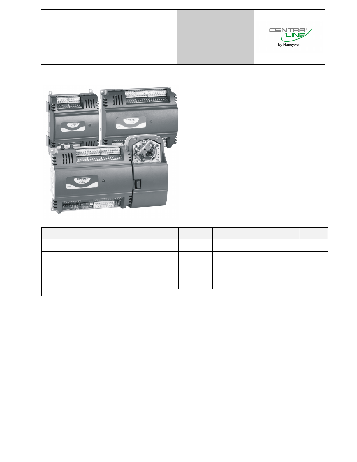
LYNX BACnet® Programmable
A
(A
VAV/Unitary Controllers
Product Data
GENERAL
The BACnet MS/TP LYNX controllers are designed to control
HVAC equipment.
LYNX controllers provide many options and advanced system
features that allow state-of-the-art commercial building
control. Each LYNX controller is programmable and configurable using the COACH
LYNX BACnet controllers require the LYNX BACnet Programmable Feature to be licensed in COACH
LYNX controllers are designed for use in VAV (Variable Air
Volume) and Unitary HVAC control applications. Each controller contains a host microcontroller to run the main HVAC
application and a second microcontroller for BACnet MS/TP
network communications. Each controller has flexible,
universal inputs for wall modules, digital inputs, and a mix of
analog and digital triac outputs (see Table 1). The models
CLLYVB6436AS, CLLYVB0000AS, and CLLYVB4022AS
include an actuator.
AX
software.
AX
.
Table 1. Controller configurations
model type
CLLYUB1012S unitary 1(A 0 1 2 NO NO
CLLYUB4024S unitary 4(A 0 2 4 NO NO
CLLYUB6438S unitary 6 4 3 8 NO NO
CLLYVB0000AS VAV 0 0 0 0 YES YES
CLLYVB4022AS VAV 4(A 0 2 2 YES YES
CLLYVB4024NS VAV 4(A 0 2 4 YES NO
CLLYVB6436AS VAV 6 4 3 6 YES YES
CLLYVB6438NS VAV 6 4 3 8 YES NO
One Universal Input (UI-1*) is selectable as a fast digital pulse meter.
All of the LYNX controllers communicate via an EIA-485 BACnet MS/TP communication network, capable of baud rates of
between 9.6 and 115.2 kbits/sec.
The LYNX controllers are field-mountable to either a panel or a DIN rail.
Universal
Inputs (UI)
Digital
Inputs (DI)
nalog Out-
puts (AO)
Digital Out-
puts (DO)
velocity pressure
sensor (Microbridge)
floating
actuator
Copyright © 2015 Honeywell GmbH All Rights Reserved EN0Z-0959GE51 R0615
Page 2
LYNX BACNET PROGRAMMABLE, VAV/UNITARY CONTROLLERS – PRODUCT DATA
TECHNICAL DATA
GENERAL SPECIFICATIONS
Rated voltage: 20 … 30 Vac; 50/60 Hz
Power consumption: 100 VA for controller and all connected
Controller-only load: 5 VA max. (S- and NS-models)
Controller + actuator load: 9 VA max. (AS-models)
Wall modules
output:
VAV OPERATING & STORAGE TEMPERATURE AMBIENT RATING
VAV models: 0 … +50 °C
Unitary models: -40 … +65.5 °C
Relative humidity: 5 … 95%, non-condensing
LED: Provides status for normal operation, con-
VELOCITY PRESSURE SENSOR (VAV MODELS)
Operating range: 0 … 374 Pa
FLOATING ACTUATOR (AS-models)
Rotation stroke: 95° ± 3° for CW/CCW-opening dampers
Torque rating: 5 Nm
Runtime for 90° rotation: 90 sec at 60 Hz
Operating temperature: -20 … +60 °C
REAL-TIME CLOCK
Operating range: 24-hr, 365-day, multi-year calendar, incl.
Power failure back-up: 24 hrs at 0 … +38 °C,
Accuracy: ±1 minute per month at 25 °C
DIGITAL INPUT (DI) CIRCUITS
Voltage rating: 0 … 30 Vdc open circuit
Input type: Dry contact to detect open / closed circuit
Operating range: Open circuit = FALSE,
Resistance: Open circuit > 3k ,
DIGITAL TRIAC OUTPUT (DO) CIRCUITS
Voltage rating: 20 … 30 Vac at 50/60 Hz
Current rating: 25 … 500 mA continuous, and 800 mA
ANALOG OUTPUT (AO) CIRCUIT
Configuration for current /
voltage:
Configuration as digital
outputs:
Analog current outputs
Current output range: 4 … 20 mA
Output load resistance: 550 , max.
Analog voltage outputs
Voltage output range: 0 … 10 Vdc
Max. output current: 10.0 mA
UNIVERSAL INPUT (UI) CIRCUITS
See Table 2 for UI circuit specifications.
power
loads (incl. actuator on AS-models)
20 Vdc ± 10% at 75 mA, max.
troller download process, alarms, manual
mode, and error conditions
day of week and configuration for automatic daylight savings time adjustment to
occur at 2:00 a.m. local times on
configured start and stop dates
22 hrs at 38 … 50 °C
closed circuit = TRUE
closed circuit < 500
(AC rms) for 60 ms.
Up to 3 analog outputs can be individually
configured for current or voltage.
FALSE (0%) -> 0 Vdc (0 mA)
TRUE (100%) -> max., 11 Vdc (22 mA)
Table 2. Universal input circuit specifications
input type sensor type operating range
Room/Zone Discharge
Air Outdoor Air Temp.
Outdoor Air
Temperature
Resistive Input Generic 100 …100 k
Voltage Input Transducer,
Discrete Input Dry Contact
Pulse Input(A Counter/Meter Max. frequency: 15 Hz
(A
One Universal Input (UI-1*) is selectable as a fast digital pulse
meter.
NTC 20kOhm -40 ... +93 °C
PT1000
(IEC751 3850)
Controller
closure
-40 ... +93 °C
0 … 10 Vdc
OpenCircuit 3000
ClosedCircuit < 3000
Min. pulse width: 20 ms
NTC 20kOhm are recommended for use with these controllers, due to improved resolution and accuracy when
compared to the PT1000.
BEFORE INSTALLATION
The controller is available in eight models (see Table 1).
Before installing the controller, review the power, input, and
output specifications in section “Technical Data”.
Hardware driven by Triac outputs must have a min.
current draw, when energized, of 25 mA and a max.
current draw of 500 mA.
Hardware driven by the analog current outputs must have
a max. resistance of 550 , resulting in a max. voltage of
11 V when driven at 20 mA. If resistance exceeds 550 ,
voltages up to 18 Vdc are possible at the analog output
terminal.
WARNING
Electrical Shock Hazard.
Can cause severe injury, death or property
damage.
To prevent electrical shock or equipment damage,
disconnect power supply before beginning wiring or
making wiring connections.
INSTALLATION
The controller must be mounted in a position that allows
clearance for wiring, servicing, removal, connection of the
BACnet MS/TP Molex connector and access to the MS/TP
MAC address DIP switches (see Fig. 12).
The controller may be mounted in any orientation.
IMPORTANT
Avoid mounting in areas where acid fumes or other
deteriorating vapors can attack the metal parts of the
controller, or in areas where escaping gas or other
explosive vapors are present. See Fig. 4 and Fig. 6 for
mounting dimensions.
EN0Z-0959GE51 R0615 2
Page 3
LYNX BACnet PROGRAMMABLE, VAV/UNITARY CONTROLLERS – PRODUCT DATA
In the case of the AS-models, first the actuator and then the
controller is mounted. For the other models, see section
“Mount Controller” on page 4 to begin the installation.
Mounting Actuator onto Damper Shaft (ASModels)
The AS-models include the direct-coupled actuator with
DECLUTCH button, which is shipped hard-wired to the
controller.
The actuator mounts directly onto the VAV box damper shaft
and has up to 5 Nm torque, 90° stroke, and 90-sec timing at
60 Hz. The actuator is suitable for mounting onto a 10 to 13
mm square or round VAV box damper shaft. The min. VAV
box damper shaft length is 40 mm.
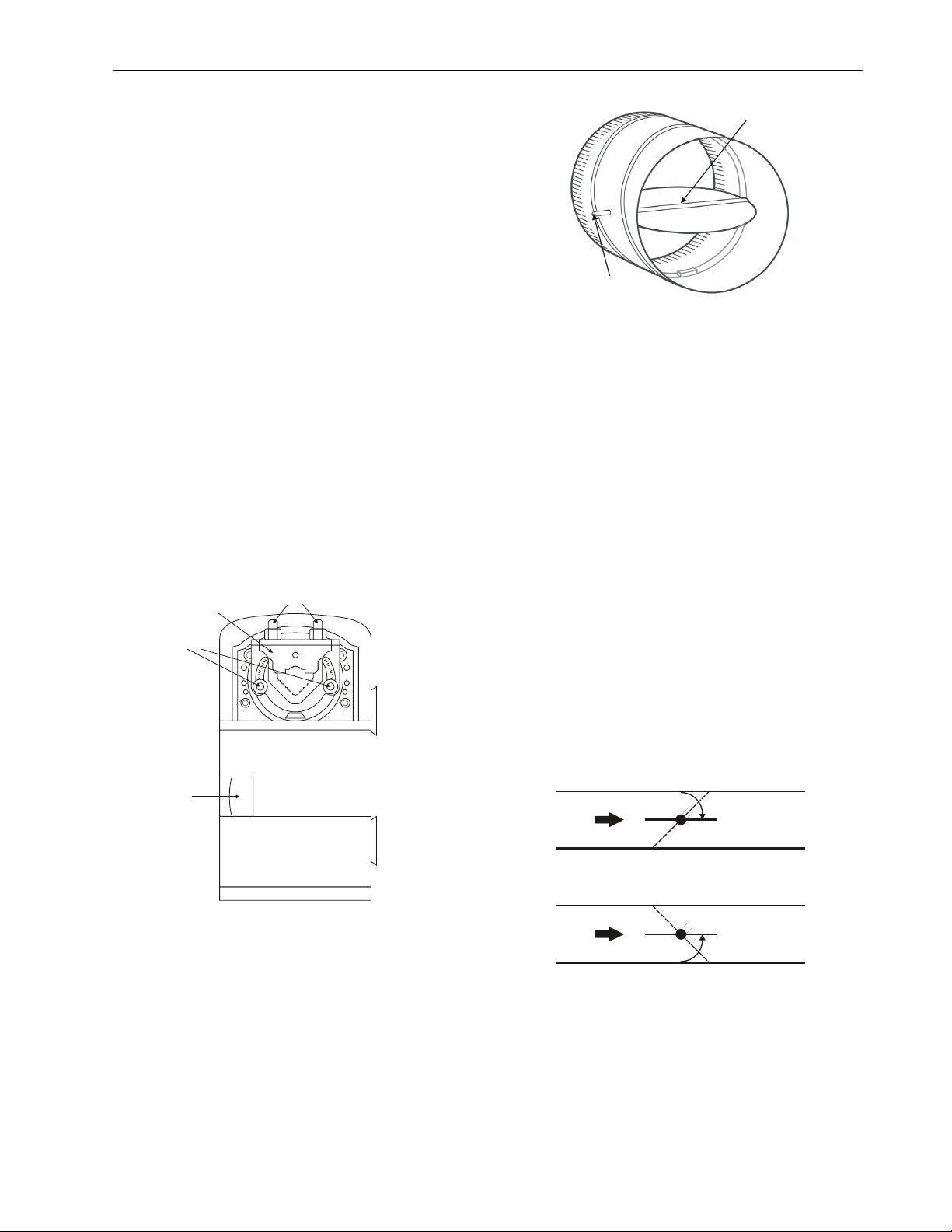
The two mechanical end-limit set screws control the amount
of rotation from 12° to 95°. These set screws must be
securely fastened in place. To ensure tight closing of the
damper, the shaft adapter has a total rotation stroke of 95°
(see Fig. 1).
NOTE 1: The actuator is shipped with the mechanical end
NOTE 2: The DECLUTCH button, when pressed, allows you
LIMIT SET SCREWS (2)
limit set screws set to 95° of rotation. Adjust the
two set screws closer together to reduce the
rotation travel. Each “hash mark” indicator on the
bracket represents approximately 6.5° of rotation
per side.
to rotate the universal shaft adapter (see Fig. 1).
UNIVERSAL SHAFT
UNIVERSAL SHAFT
ADAPTER
MECHANICAL END
DECLUTCH
BUTTON
CLAMPING BOLTS (2)
DAMPER
DAMPER SHAFT
ROTATES CW
TO OPEN
Fig. 2. Damper with 90° clockwise rotation to open
IMPORTANT
Mount actuator flush with damper housing or add a
spacer between the actuator mounting surface and
damper box housing.
Before Mounting Actuator onto Damper
Shaft (AS-Models)
Tools required:
Phillips #2 screwdriver - end-limit set screw adjustment
8 mm wrench - centering clamp
Before mounting the actuator onto the VAV box damper shaft,
determine the following:
1. Determine the damper shaft diameter. It must be
10…13 mm.
2. Determine the length of the damper shaft. If the length of
the VAV box damper shaft is less than 40 mm, the
actuator cannot be used.
3. Determine the direction the damper shaft rotates to open
the damper (CW or CCW) (see Fig. 3). Typically, there is
an etched line on the end of the damper shaft indicating
the position of the damper. In Fig. 2, the indicator shows
the damper open in a CW direction.
4. Determine the damper full opening angle (45, 60, or 90°).
In Fig. 2, the damper is open to its full open position of
90°.
TYPE A DAMPER
AIR
FLOW
CW TO OPEN, CCW TO CLOSE
TYPE B DAMPER
Fig. 1. Floating actuator
IMPORTANT
Determine the damper rotation and opening angle prior to
installation. See Fig. 2 and Fig. 3 for examples.
Fig. 3. Determining rotation direction (CW or CCW) for
AIR
FLOW
CCW TO OPEN, CW TO CLOSE
damper opening
EN0Z-0959GE51 R0615
3
Page 4
LYNX BACNET PROGRAMMABLE, VAV/UNITARY CONTROLLERS – PRODUCT DATA
A
A
V
A
V
V
A
V
Mounting Actuator Onto Damper Shaft (ASModels)
The unit is shipped with the actuator set to rotate open in the
clockwise (CW) direction to a full 95°. The extra 5° ensures a
full opening range for a 90° damper.
The installation procedure varies depending on the damper
opening direction and angle:
1) If the damper rotates CW to open, and the angle of the
damper open-to-closed is 90°:
a) Manually open the damper fully (rotate CW).
b) Using the DECLUTCH button, rotate the universal
shaft adapter fully CW.
c) Mount the actuator to the VAV damper box and shaft.
d) Tighten the two bolts on the centering clamp (8 mm
wrench; 8...10 Nm torque). When the actuator closes,
the damper rotates CCW 90° to fully close.
2) If the damper rotates CW to open, and the angle of the
damper open-to-closed is 45 or 60°:
a) Manually open the damper fully (rotate CW).
b) The actuator is shipped with the mechanical end-limits
set at 95°. Adjust the two mechanical end-limit set
screws to provide the desired amount of rotation.
Adjust the two set screws closer together to reduce the
rotation travel.
c) Tighten the two mechanical end-limit screws (Phillips
#2 screwdriver; (3.0-3.5 Nm torque).
d) Using the DECLUTCH button, rotate the universal
shaft adapter fully CW.
e) Mount the actuator to the VAV damper box and shaft.
f) Tighten the two bolts on the centering clamp (8 mm
wrench; 8...10 Nm torque).
g) When the actuator closes, the damper rotates CCW
either 45 or 60° to fully close.
3) If the damper rotates CCW to open, and the angle of the
damper open-to-closed is 90°:
a) Manually open the damper fully (rotate CCW).
b) Using the DECLUTCH button, rotate the universal
shaft adapter fully CCW.
c) Mount the actuator to the damper box and shaft.
d) Tighten the two bolts on the centering clamp (8 mm
wrench; 8...10 Nm torque). When the actuator closes,
the damper rotates CW 90° to fully close.
4) If the damper rotates CCW to open, and the angle of the
damper open-to-closed is 45 or 60°:
a) Manually open the damper fully (rotate CCW).
b) The actuator is shipped with the mechanical end-limits
set at 95°. Adjust the two mechanical end-limit set
screws to provide the desired amount of rotation.
Adjust the two set screws closer together to reduce the
rotation travel.
c) Tighten the two mechanical end-limit screws (Phillips
#2 screwdriver; (3.0-3.5 Nm torque).
d) Using the DECLUTCH button, rotate the universal
shaft adapter fully CCW.
e) Mount the actuator to the VAV damper box and shaft.
f) Tighten the two bolts on the centering clamp (8 mm
wrench; 8...10 Nm torque).
g) When the actuator closes, the damper rotates CW
either 45 or 60° to fully close.
IMPORTANT
Special precautions must be taken for dampers that
open in a CCW direction. The actuator is shipped with
its rotation direction set to CW to open, which applies
to the damper direction in steps 1 and 2 above. If the
damper shaft rotates in the CCW direction to open, the
controller software must be programmed to change the
rotation to “Reverse to Open,” which applies to the
damper direction in steps 3 and 4 above.
IMPORTANT
To avoid the possibility of over-pressurizing the duct
work on fan start-up, it is advisable to leave the
dampers in an open position after installation. To
prevent over-pressurization in the duct work on fan
start-up, use the DECLUTCH button (see Fig. 1) to
open the box damper on powered-down controllers. To
declutch, press and hold the DECLUTCH button, thus
disengaging the motor. Turn the damper shaft until the
damper is open and then release the DECLUTCH
button. When power is restored to the controller, the
controller synchronizes the damper actuator, so that
the damper is in the correct position upon start-up.
Mount Controller
NOTE: The controller may be wired before mounting to a
Terminal blocks are used to make all wiring connections to
the controller. Attach all wiring to the appropriate terminal
blocks (see section “Wiring” on page 6).
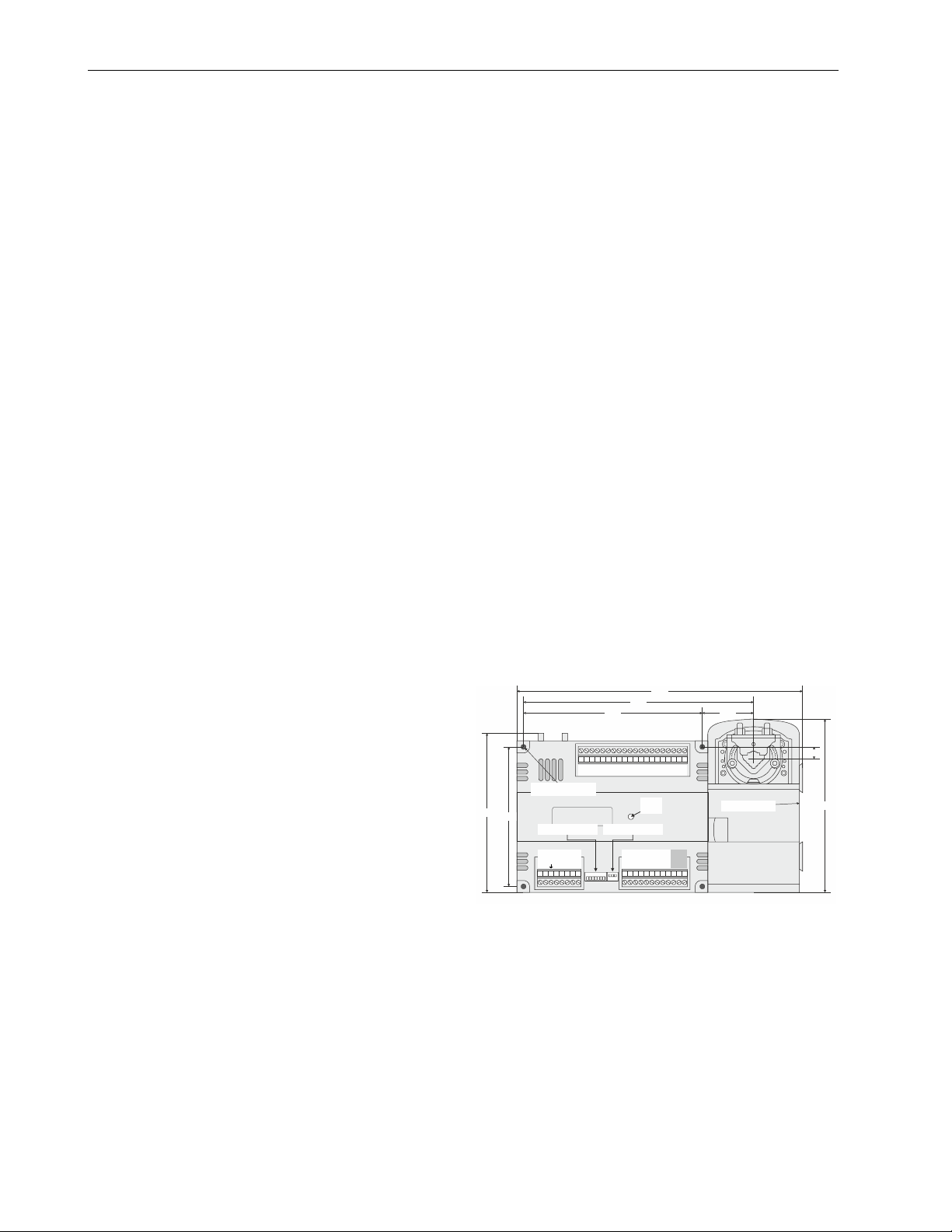
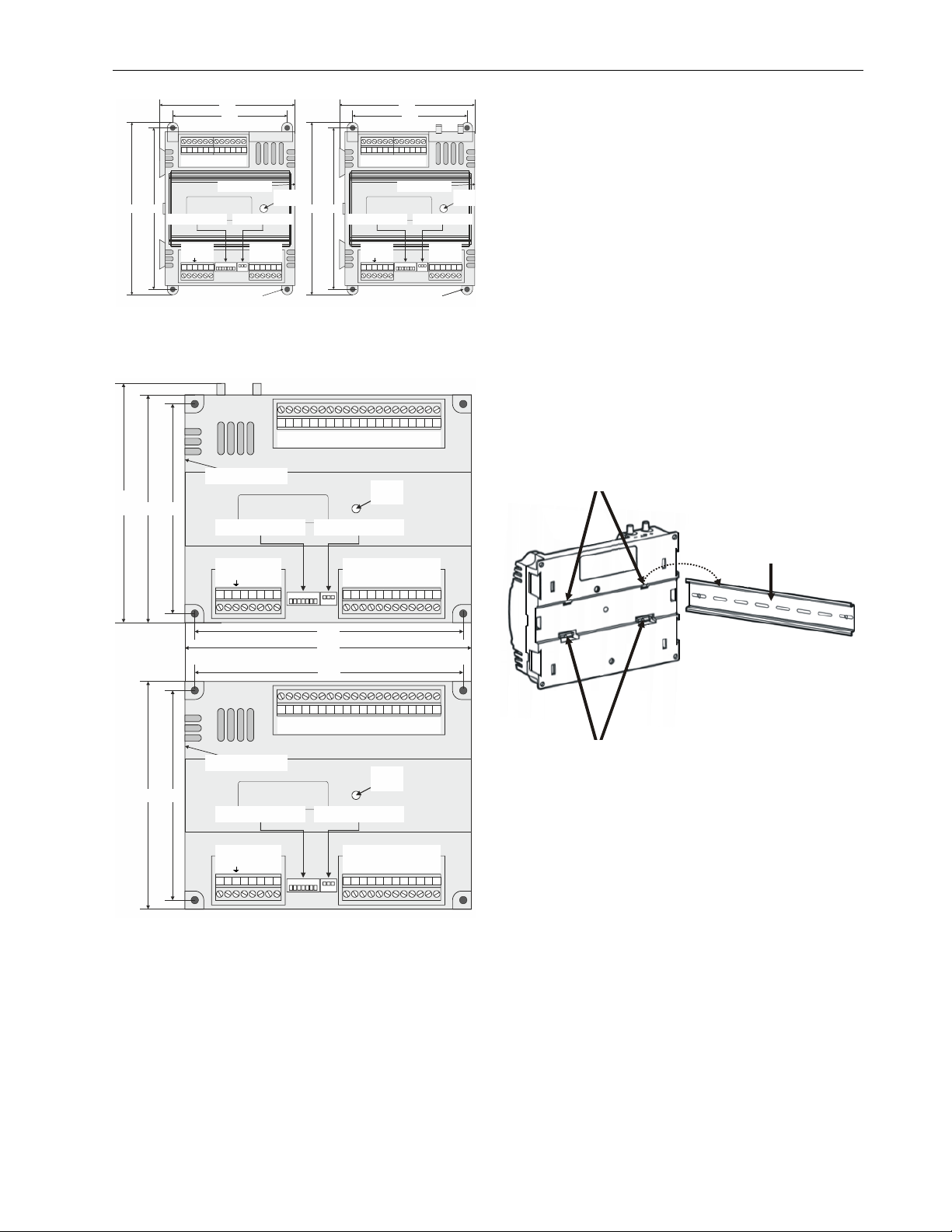
See Fig. 4 and Fig. 6 for panel mounting dimensions. See
Fig. 7 for DIN rail mounting.
146
Fig. 4. Duct mounting, dimensions in mm (AS-models)
panel or DIN rail.
2122 23 24 2526 27 28 29 30 3132 33 34 35 36 37 38 39 40
AO-1
AO-2
AO-3
COM
PANEL MOUNTING
HOLE (4 X 4.5)
128
AS MODELS
BACnet MS/TP MAC
ADDRESS DIP SWITCHES
B
B
24
20
EGND
S-BUS
S-BUS
24
C+
C-
DC
C
C
COM
1 3 4 5 62 7 8 9 10 11 12 13 1415 16 17 18 19 20
211
164
DI-1
DI-2
COM
COM
DI-3
DI-4
20
UI-1
COM
DC
HOST
STATUS
LED
LOCAL BACnet MS/TP
MOLEX CONNECTOR PINS
DO-1
DO-2
DO-4
COM
DO-3
UI-2
COM
262
211
UI-3
COM
UI-4
UI-5
COM
UI-6
DEPTH = 57
DO-6
DO-8
COM
COM
DO-5
DO-7
11
159
Panel Mounting
The controller enclosure is constructed of a plastic base plate
and a plastic factory-snap-on cover.
EN0Z-0959GE51 R0615 4
Page 5
LYNX BACnet PROGRAMMABLE, VAV/UNITARY CONTROLLERS – PRODUCT DATA
V
V
V
V
A
A
V
A
V
V
A
122 122
105 105
13 14 15 16 17 18 19 2021 22 23 24 1314 15 16 17 18 19 20 21 22 23 24
DO-2
COM
DO-1
COM
AO-1
UI-4
AO-2
COM
UI-3
UI-2
COM
UI-1*
HOST
STATUS
159 159149 149
CLLYUB4024S CLLYVB4024NS
BACnet MS/TP MAC
ADDRESS DIP SWITCHES
24
20
EGND
S-BUS
S-BUS
24VAC COM
AC
DC
1 3 4 5 62 7 8 9 10 1112 1 3 4 5 62 7 8 9 10 11 12
PANEL MOUNTING
HOLE (4 X 4.5)
LED
LOCAL BACnet MS/TP
MOLEX CONNECTOR PINS
BAC+
BAC-
SHIELD
DO-3
COM
DO-4
DO-2
COM
DO-1
COM
AO-1
AO-2
BACnet MS/TP MAC
ADDRESS DIP SWITCHES
24
20
EGND
S-BUS
S-BUS
24VAC COM
AC
DC
PANEL MOUNTING
HOLE (4 X 4.5)
UI-4
COM
UI-3
UI-2
COM
UI-1*
DEPTH = 57DEPTH = 57
LOCAL BACnet MS/TP
MOLEX CONNECTOR PINS
HOST
STATUS
LED
BAC+
BAC-
SHIELD
DO-3
COM
DO-4
Fig. 5. Panel mounting – dimensions (mm) for
CLLYUB1012S, CLLYUB4024S, and CLLYVB4024NS, only
(CLLYUB4024S and CLLYVB4024NS shown)
21 22 23 24 25 26 27 28 29 30 31 32 33 34 35 36 37 38 39 40
AO-1 AO-1
DI-1 DI-1
DI-2 DI-2
AO-2 AO-2
AO-3 AO-3
COM COM
COM COM
COM COM
DI-3 DI-3
DI-4 DI-4
20VDC 20VDC
UI-1 UI-1
UI-2 UI-2
UI-3 UI-3
UI-4 UI-4
UI-5 UI-5
UI-6 UI-6
COM COM
COM COM
DO-6 DO-6
DO-8 DO-8
COM COM
COM COM
DO-5 DO-5
DO-7 DO-7
146
139
128
DEPTH = 57
NS MODELS
BACnet MS/TP MAC
ADDRESS DIP SWITCHES
24VAC
BAC+
20VDC
EGND
S-BUS
S-BUS
24VAC COM
BAC-
COM COM
HOST
STATUS
LED
LOCAL BACnet MS/TP
MOLEX CONNECTOR PINS
DO-1 DO-1
DO-2 DO-2
DO-4 DO-4
COM COM
COM COM
DO-3 DO-3
The controller can be mounted in any orientation. Ventilation
openings are designed into the cover to allow proper heat
dissipation, regardless of the mounting orientation.
DIN Rail Mounting (S- and NS-models)
To mount the S- and NS-models onto a DIN rail, see Fig. 7
and perform the following steps:
1. Holding the controller with its top tilted in towards the DIN
rail, hook the two top tabs on the back of the controller
onto the top of the DIN rail.
2. Push down and in to snap the two bottom flex connectors
of the controller onto the DIN rail.
IMPORTANT
To remove the controller from the DIN rail, perform the
following:
1. Push straight up from bottom to release top tabs.
2. Rotate the top of the controller out towards you and
pull the controller down and away from the DIN rail to
release the bottom flex connectors.
TOP TABS
DIN RAIL
1 3 4562
7
8
9 10 11 12 13 14 15 16 17 18 19 20
164
174
164
21 22 23 24 25 26 27 28 29 30 31 32 33 34 35 36 37 38 39 40
139
128
DEPTH = 57
S MODELS
BACnet MS/TP MAC
ADDRESS DIP SWITCHES
24
C
134
B
20
EGND
S-BUS
S-BUS
24
C+
DC
C
COM
5 627 8
B
C-
LOCAL BACnet MS/TP
MOLEX CONNECTOR PINS
9 10
HOST
STATUS
11 121314
LED
15 161718 19 20
Fig. 6. Panel mounting, dimensions in mm (S- and NS-
models)
NOTE: The controller is designed so that the cover does
not need to be removed from the base plate for
either mounting or wiring.
The controller mounts using four screws inserted through the
corners of the base plate. Fasten securely with four screws.
BOTTOM FLEX
CONNECTORS
Fig. 7. Controller DIN rail mounting (S- and NS-models)
Piping (AS- and NS-models)
Air Flow Pick-Up
For AS- and NS-models, connect the air flow pickup to the
two restrictor ports on the controller (see Fig. 8).
NOTE 1: Use tubing with 6 mm outside diameter and 1 mm
NOTE 2: Always use a fresh cut on the end of the tubing that
Connect the high-pressure or upstream tube to the plastic
restrictor port labeled (+), and the low-pressure or downstream tube to the restrictor port labeled (-). See labeling in
Fig. 8. When twin tubing is used from the pickup, split the
pickup tubing a short length to accommodate the connections.
wall thickness.
connects to the air flow pickups and the restrictor
ports on the controller.
EN0Z-0959GE51 R0615
5
Page 6

LYNX BACNET PROGRAMMABLE, VAV/UNITARY CONTROLLERS – PRODUCT DATA
NOTE 1: If controllers are mounted in unusually dusty or
NOTE 2: The tubing from the air flow pickup to the controller
NOTE 3: Use caution when removing tubing from a con-
dirty environments, an inline, 5-micron disposable
air filter (use 5-micron filters compatible with
pneumatic controls) is recommended for the highpressure line (marked as +) connected to the air
flow pickup.
should not exceed 1 m. Any length greater than
this will degrade the flow sensing accuracy.
nector. Always pull straight away from the connector or use diagonal cutters to cut the edge of
the tubing attached to the connector. Never
remove by pulling at an angle.
AIR FLOW
PICK-UP
RESTRICTOR
PORTS
P
2222222222
5
1234
67890
3
1
NS- and AS-models
It is important to understand these interrelationships early in
the job engineering process, to ensure proper implementation
when configuring the controllers. See the controller
Application Guides.
Power Budget
A power budget must be calculated for each device to determine the required transformer size for proper operation. A
power budget is simply the sum of the max. power draw
ratings (in VA) of all the devices to be controlled. This
includes the controller itself and any devices powered from
the controller, such as equipment actuators and various
contactors and transducers.
IMPORTANT
When multiple controllers operate from a single
transformer, connect the same side of the transformer
secondary to the same power input terminal in each
device. The earth ground terminal (terminal 3) must be
connected to a verified earth ground for each controller
in the group (see Fig. 10).
Half-wave devices and full-wave devices must not use
the same AC transformer. If a LYNX controller is to
share its power supply with another device, make sure
the other device utilizes a half-wave rectifier and that
the polarity of the wiring is maintained.
Wiring
All wiring must comply with applicable electrical codes and
ordinances, or as specified on installation wiring diagrams.
Controller wiring is terminated to the screw terminal blocks
located on the top and the bottom of the device.
Fig. 8. Air flow pick-up connections
Power
Before wiring the controller, determine the input and output
device requirements for each controller used in the system.
Select input and output devices compatible with the controller
and the application. Consider the operating range, wiring
requirements, and the environment conditions when selecting
input/output devices. When selecting actuators for modulating
applications, consider using floating control. In direct digital
control applications, floating actuators will generally provide
control action equal to or better than an analog input actuator
for lower cost.
Determine the location of controllers, sensors, actuators, and
other input/output devices and create wiring diagrams. See
Fig. 14 through Fig. 20 for typical controller wiring configurations.
The application engineer must review the control job requirements. This includes the sequences of operation for the controller, and for the system as a whole. Usually, there are
variables that must be passed between the controller and
other controllers that are required for optimum system wide
operation. Typical examples include the outdoor air temperature, the demand limit control signal, and the smoke
control mode signal.
WARNING
Electrical Shock Hazard.
Can cause severe injury, death or property
damage.
To prevent electrical shock or equipment damage,
disconnect power supply before beginning wiring or
making wiring connections.
NOTE 1: For multiple controllers operating from a single
transformer, the same side of the transformer
secondary must be connected to the same power
input terminal in each controller. Controller configurations will not necessarily be limited to three
devices, but the total power draw, including
accessories, cannot exceed 100 VA when powered
by the same transformer (U.S., only). For power
and wiring recommendations, See section “Power”
on page 6. The earth ground terminal (terminal 3)
must be connected to a verified earth ground for
each controller in the group (see Fig. 10).
NOTE 2: All loads on the controller must be powered by the
same transformer powering the controller itself. A
controller can use separate transformers for controller power and output power.
EN0Z-0959GE51 R0615 6
Page 7

LYNX BACnet PROGRAMMABLE, VAV/UNITARY CONTROLLERS – PRODUCT DATA
NOTE 3: A jumper should be installed between 24 VAC
COM (term. 2) and EGND (term. 3). Further,
EGND (term. 3) should be connected to a verified
earth ground, and kept as short as possible.
NOTE 4: Do not connect the universal input COM terminals,
analog output COM terminals or the digital
input/output COM terminals to earth ground. See
Fig. 13 through Fig. 18 for wiring examples.
The 24 Vac power from an energy limited Class II power
source must be provided to the controller. To conform to
Class II restrictions (U.S., only), the transformer must not be
larger than 100 VA.
Fig. 9 depicts a single controller using one transformer.
IMPORTANT
Power must be OFF prior to connecting to or removing
connections from the 24 Vac power (24 Vac/24 Vac
COM), earth ground (EGND), and 20 Vdc power (20
Vdc) terminals.
IMPORTANT
Use the heaviest gauge wire available, up to 2.0 mm
with a min. of 1.0 mm
2
, for all power and earth ground
2
wiring.
Screw-type terminal blocks are designed to accept up
to one 2.0 mm
ductors. More than two wires that are 2.0 mm
2
conductor or up to two 1.0 mm2 con-
2
can be
connected with a wire nut. Include a pigtail with this
wire group and attach the pigtail to the terminal block.
IMPORTANT
Connect terminal 2, (the 24 Vac common [24 VAC
COM] terminal) to earth ground (see Fig. 9).
NOTE: Unswitched 24 Vac power wiring can be run in the
same conduit as the BACnet MS/TP cable.
CONNECT POWER TO
TERMINALS 1 AND 2.
5
1234
OUTPUT
DEVICE POWER
678
EARTH GROUND
(TERMINAL 3)
COM
TRANSFORMER
24 VAC
EARTH
WHEN CONNECTING POWER TO THE LYNX BACnet
CONTROLLER, CONNECT THE COM LEG OF THE VAC
SECONDARY CIRCUIT TO A KNOWN EARTH GROUND.
GROUND
9
LI N E V O LTAGE
> 150 VAC
Fig. 9. Power wiring details for one LYNX controller per
transformer
More than one controller can be powered by a single transformer. Fig. 10 shows power wiring details for multiple controllers.
NOTE: Controller configurations are not necessarily limited
to three devices, but the total power draw,
including accessories, cannot exceed 100 VA
when powered by the same transformer (U.S.,
only). For power wiring recommendations, see
section “Power” on page 6.
CONNECT POWER TO
TERMINALS 1 AND 2.
EARTH GROUND
(TERMINAL 3)
CONNECT POWER TO
TERMINALS 1 AND 2.
EARTH GROUND
(TERMINAL 3)
CONNECT POWER TO
TERMINALS 1 AND 2.
123456781234567812345678 999
EARTH GROUND
(TERMINAL 3)
COM
OUTPUT DEVICE POWER
24 VAC
WHEN CONNECTING POWER TO THE LYNX BACnet
CONTROLLER, CONNECT THE COM LEG OF THE VAC
SECONDARY CIRCUIT TO A KNOWN EARTH GROUND.
GROUND
Fig. 10. Power wiring details for two or more LYNX
,
controllers per transformer
Communications
Each LYNX controller uses a BACnet MS/TP communications
port. The controller’s data is presented to other controllers
over a twisted-pair MS/TP network, which uses the EIA-485
signaling standard capable of the following baud rates: 9.6,
19.2, 38.4, 76.8 or 115.2 kilobits per sec (configured at global
controller). The LYNX controllers are master devices on the
MS/TP network. Each LYNX controller uses a high-quality
EIA-485 transceiver and exerts ¼ unit load on the MS/TP
network.
Cabling should be selected that meets or exceeds the
BACnet Standard which specifies the following: An MS/TP
EIA-485 network shall use shielded, twisted-pair cable with
characteristic impedance of 100…130 . Distributed
capacitance between conductors shall be less than 100 pF
per meter. Distributed capacitance between conductors and
shield shall be less that 200 pF per meter. Foil or braided
shields are acceptable. The Honeywell tested and
recommended MS/TP cable is Honeywell Cable 3322 (18
AWG, 1-Pair, Shielded, Plenum cable), alternatively
Honeywell Cable 3251 (22 AWG, 1-Pair, Shielded, Plenum
cable) is available and meets the BACnet Standard requirements (www.honeywellcable.com).
The max. BACnet MS/TP network Bus segment length is
1,219 m using recommended wire. Repeaters must be used
when making runs longer than 1,219 m. A max. of three
repeaters can be used between any two devices.
Setting the MS/TP MAC Address
The MS/TP MAC address for each device must be set to a
unique value in the range of 0-127 on an MS/TP network
segment (address 0, 1, 2, & 3 should be avoided as they are
commonly used for the router, diagnostic tools, and as spare
addresses). DIP switches on the LYNX controller are used to
set the controller's MAC address.
To set the MS/TP MAC address of a LYNX controller:
TRANSFORMER
120/240 VAC
EARTH
EN0Z-0959GE51 R0615
7
Page 8

LYNX BACNET PROGRAMMABLE, VAV/UNITARY CONTROLLERS – PRODUCT DATA
1. Find an unused MAC address on the MS/TP network to
which the LYNX controller connects.
2. Locate the DIP switch bank on the LYNX for addressing.
This is labeled “MAC Address.”
3. With the LYNX Controller powered down, set the DIP
switches for the MAC Address you want. Add the value of
DIP switches set to ON to determine the MAC address.
See Table 3. For example, if only DIP switches 1, 3, 5,
and 7 are enabled, the MAC address would be 85 (1 + 4 +
16 + 64 = 85).
NOTE: See Fig. 12 for DIP switch orientation and arrange-
ment.
Table 3. DIP switch values for MS/TP MAC address
DIP
VALUE
7 6 5 4 3 2 1
64 32 16 8 4 2 1
Setting the Device Instance Number
The Device Instance Number must be unique across the
entire BACnet system network because it is used to uniquely
identify the BACnet devices. It may be used to conveniently
identify the BACnet device from other devices during
installation. The LYNX controller’s Device Instance Number is
automatically set when it is added to a WEBStation-AX
project.
The Device Instance Number can be changed by the user,
which may be necessary when integrating with a third party or
when attempting to replace an existing controller and it is
desired to maintain the existing Device Instance Number.
To edit the Device Instance Number using WEBs AX:
1. Identify an unused Device Instance Number on the
BACnet Network, in the range of 0 - 4194302.
2. Open the LYNX BACnet Device Mgr View
a. Double click on the BACnet Network located in the
navigation tree.
b. Select the LYNX controller to be modified.
c. Click on the Edit button.
d. Enter an unused value in the Device ID field.
e. Select OK
3. Right click on the LYNX Controller and select “Actions >
Write Device Instance” to complete the update.
Termination Resistors
Matched terminating resistors are required at each end of a
segment bus wired across (+) and (-). Use matched precision
resistors rated ¼ W ±1% / 80…130 . Ideally, the value of the
terminating resistors should match the rated characteristic
impedance of the installed cable. E.g., if the installed MS/TP
cable has a listed characteristic impedance of 120 , install
120 matched precision resistors.
NOTE: LYNX controllers do not provide network biasing.
Shield Terminating
Following proper MS/TP cabling shield grounding procedures
is important to minimize the risk of communication problems
and equipment damage caused by capacitive coupling.
Capacitive coupling is caused by placing MS/TP cabling close
to lines carrying higher voltage. The shield should be
grounded on only one end of the MS/TP segment (typically,
on the router end). Tie the shield through using the SHLD
(terminal 4) on the LYNX Controller.
Sylk™ Bus
Sylk is a two-wire, polarity-insensitive bus that provides both
18 Vdc power and communications between a Sylk-enabled
sensor and a Sylk-enabled controller. Using Sylk-enabled
sensors saves I/O on the controller and is faster and cheaper
to install since only two wires are needed and the bus is
polarity-insensitive. Sylk sensors are configured using the
latest release of the LYNX Tool for COACH
BAC -
BAC +
SHIELD
ADD APPROPRIATE TERMINATION RESISTOR
12345678 1234567812345678 999
BETWEEN BAC+ BAC- TERMINALS.
BAC -
BAC +
SHIELD
AX
.
BAC -
BAC +
SHIELD
Fig. 11. Termination modules (BACnet MS/TP daisy chain
connections)
Wiring Details
Each controller is shipped with the digital outputs, which
switch the 24 Vac to the load (high side).
The three analog outputs (AO) are used to control modulating
heating, cooling and economizer equipment. Any AO may be
used as a digital output, as follows:
False (0%) produces 0 Vdc (0 mA)
True (100%) produces the max. 11 Vdc (22 mA)
The wiring connection terminals described in Table 4 are
shown in Fig. 12.
IMPORTANT
If the controller is not connected to a good earth
ground, the controller's internal transient protection
circuitry is compromised and the function of protecting
the controller from noise and power line spikes cannot
be fulfilled. This could result in a damaged circuit
board and require replacement of the controller. See
installation diagrams for specific wiring.
All controllers have terminal arrangements similar to the
example shown in Fig. 12 as described in Table 4.
EN0Z-0959GE51 R0615 8
Page 9

LYNX BACnet PROGRAMMABLE, VAV/UNITARY CONTROLLERS – PRODUCT DATA
A
A
A
A
Table 4. Description of wiring terminals (CLLYUB6438S,
CLLYVB6436AS, and CLLYVB6438S)
TERMINAL LABEL CONNECTION
INPUT POWER & GROUND
1 24 VAC 24 VAC POWER
(
2
24 VAC COM 24 VAC POWER
(
3
EGND EARTH GROUND
4 SHLD SHIELD
5 SBUS 1 SYLK
6 SBUS 2 SYLK
NETWORK CONNECTIONS
7 BAC+ BACnet COMMUNICATIONS
8 BAC- BACnet COMMUNICATIONS
DIGITAL OUTPUTS
9 DO-1 DIGITAL OUTPUT
10 DO-2 DIGITAL OUTPUT
11 COM COMMON
12 DO-3 DIGITAL OUTPUT
13 DO-4 DIGITAL OUTPUT
14 COM COMMON
15 DO-5 DIGITAL OUTPUT
16 DO-6 DIGITAL OUTPUT
17 COM COMMON
18(B DO-7 DIGITAL OUTPUT
19(B DO-8 DIGITAL OUTPUT
20(B COM COMMON
ANALOG OUTPUTS(C
21 AO-1 ANALOG OUTPUT
22 COM COMMON
23 AO-2 ANALOG OUTPUT
24 AO-3 ANALOG OUTPUT
25 COM COMMON
DIGITAL INPUTS(D
26 DI-1 DIGITAL INPUT
27 DI-2 DIGITAL INPUT
28 COM COMMON
29 DI-3 DIGITAL INPUT
30 DI-4 DIGITAL INPUT
ATTACHED DEVICE(S) POWER
31 20 VDC 20 VDC POWER
UNIVERSAL INPUTS
32 UI-1* UNIVERSAL INPUT
33 COM COMMON
34 UI-2 UNIVERSAL INPUT
35 UI-3 UNIVERSAL INPUT
36 COM COMMON
37 UI-4 UNIVERSAL INPUT
38 UI-5 UNIVERSAL INPUT
39 COM COMMON
40 UI-6 UNIVERSAL INPUT
(A
A jumper should be installed between 24 VAC COM (term. 2) and EGND
(term. 3). Further, EGND (term. 3) should be connected to a verified earth
ground.
(B
In the case of the CLLYVL6436AS controller, only, terminals 18, 19, and 20
(DO-7, DO-8, and COM) are not present. The actuator is internally hardwired to
these terminals.
(C
Analog outputs may be configured as digital outputs and operate as follows:
FALSE (0%) -> 0 Vdc (0 mA), TRUE (100%) -> the max. 11 Vdc (22 mA)
(D
Digital inputs: open circuit = FALSE, closed circuit = TRUE
*UI-1 is selectable as a fast digital pulse meter.
Table 5. Description of wiring terminals (CLLYVB0000AS,
CLLYVB4022AS, and CLLYVB6436AS)
TERMINAL LABEL CONNECTION
INPUT POWER & GROUND
1 24 VAC 24 VAC POWER
(
2
24 VAC COM 24 VAC POWER
(
3
EGND EARTH GROUND
4 20VDC 20 VDC
5 SBUS 1 SYLK
6 SBUS 2 SYLK
NETWORK CONNECTIONS
7 BAC+ BACnet COMMUNICATIONS
8 BAC- BACnet COMMUNICATIONS
9 SHIELD SHIELD
DIGITAL OUTPUTS
10 DO-3 DIGITAL OUTPUT
11 COM COMMON
12 DO-4 DIGITAL OUTPUT
13 DO-2 DIGITAL OUTPUT
14 COM COMMON
15 DO-1 DIGITAL OUTPUT
ANALOG OUTPUTS
16 AO-2 ANALOG OUTPUT
17 COM COMMON
18 AO-1 ANALOG OUTPUT
UNIVERSAL INPUTS
19 UI-4 UNIVERSAL INPUT
20 COM COMMON
21 UI-3 UNIVERSAL INPUT
22 UI-2 UNIVERSAL INPUT
23 COM COMMON
24 UI-1* UNIVERSAL INPUT
(A
A jumper should be installed between 24 VAC COM (term. 2) and
EGND (term. 3). Further, EGND (term. 3) should be connected to a
verified earth ground.
*
UI-1 is selectable as a fast digital pulse meter.
MS/TP MAC Address DIP Switches
The MS/TP MAC address DIP switches are used to set the
unit's MAC address. Each LYNX controller on an MS/TP network must have a unique MAC address in the range of 0-127
(address 0 should be avoided as it is the Honeywell factory
default MAC address for all MS/TP devices).
MS/TP Service Connector Pins
Local device MS/TP network connection is provided via the
molex connector pins.
EN0Z-0959GE51 R0615
9
Page 10

LYNX BACNET PROGRAMMABLE, VAV/UNITARY CONTROLLERS – PRODUCT DATA
21 22 23 24 25 26 27 28 29 30 31 32 33 34 35 36 37 38 39 40
AO-1
DI-1
DI-2
AO-2
AO-3
COM
COM
COM
DI-3
DI-4
20VDC
UI-1
COM
UI-2
UI-3
COM
UI-4
UI-5
COM
WINDOW CONTACTS
(CONTACTS CLOSED
= WINDOW CLOSED)
UI-6
AIR FLOW
PICK-UP
OCCUPANCY SENSOR
(CONTACTS CLOSED
22
= OCCUPIED)
CLCM4T111
7
6
LED
5
BYPASS
4
SET-POINT
3
SENSOR
2
GND
1
HOST
STATUS
CLLYVB6438NS
BACnet MS/TP MAC
ADDRESS DIP SWITCHES
BAC+
20VDC
S-BUS
S-BUS
BAC-
24VAC
EGND
24VAC COM
1 3 4562 7 8 9 10 11 12 13 14 15 16 17 18 19 20
LOCAL BACnet MS/TP
MOLEX CONNECTOR PINS
LED
DO-1
DO-2
DO-4
DO-6
COM
COM
DO-3
DO-8
COM
DO-5
COM
DO-7
Fig. 12. LED, service, network, and terminal connections
(CLLYVB6438NS shown)
Wiring Applications (Examples)
Fig. 13 through Fig. 19 illustrate controller wiring for the
following configurations.
Typical controller wiring for VAV application using the
CLCM4T111 Wall Module and an LF20 Air Temperature
Sensor (see Fig. 13).
Typical controller wiring for VAV application with staged
reheat (see Fig. 14).
Typical controller wiring for PWM reheat and PWM
peripheral heat valve actuator (see Fig. 15).
Typical controller wiring for AHU application (see Fig. 16).
Typical controller wiring for 4…20 mA enthalpy sensors
and digital inputs (see Fig. 17).
Typical controller wiring for 4…20 mA heating, cooling,
and model ML6161 floating motor control (see Fig. 18).
Typical controller wiring for a pneumatic transducer, model
RP7517B (see Fig. 19).
25 262728 29 30 31 32 33 34 35 36 37 38 39 40
21 222324
AO-1
COM
DI-1
DI-2
AO-2
AO-3
COM
COM
DI-3
DI-4
20VDC
UI-1
COM
UI-2
UI-3
CLLYVB6438NS
DO-1
DO-2
DO-4
COM
COM
DO-3
11 121314
REHEAT STAGE 2 (OR CLOSE)
REHEAT STAGE 1 (OR OPEN)
DAMPER CLOSE
DAMPER OPEN
DO-5
15 161718 19 20
BAC+
24VAC
EGND
24VAC COM
134
24VAC BACnet MS/TP-
24VAC COM
1
BAC-
20VDC
S-BUS
S-BUS
5 627 8 9 10
BACnet MS/TP+
SHIELD
Fig. 13. Controller wiring diagram (CLLYVB6438NS
shown) for typical VAV application
NOTE 1: Earth ground wire length should be held to a
minimum. Use the heaviest gauge wire available,
up to 14 AWG (2.0 mm
AWG (1.0 mm
2
), for earth ground wire.
2
), with a minimum of 18
C770A AIR
TEMP. SENSOR
COM
UI-4
UI-5
COM
DO-6
DO-8
COM
DO-7
FAN CONTACTOR
REHEAT STAGE 3
CCW
COM
CW
UI-6
COM
SERIES OR
PARALLEL
ML6161
CONTACTORS
REHEAT STAGE
EN0Z-0959GE51 R0615 10
NOTE 2: Contacts must be suitable for dry switching, 5 V at
10 mA. Use sealed type, gold-flashed, or pimpled
contacts.
Page 11

AIR FLOW
PICK-UP
(CONTACTS CLOSED
CLLYVB6436AS
24VAC
20VDC
EGND
S-BUS
24VAC COM
LYNX BACnet PROGRAMMABLE, VAV/UNITARY CONTROLLERS – PRODUCT DATA
WINDOW CONTACTS
= WINDOW CLOSED)
BAC+
S-BUS
OCCUPANCY SENSOR
(CONTACTS CLOSED
= OCCUPIED)
22
21 22 23 24 25 26 27 28 29 30 31 32 33 34 35 36 37 38 39 40
AO-1
DI-1
DI-2
AO-2
AO-3
COM
COM
COM
DI-3
DI-4
20VDC
UI-1
COM
DO-1
DO-2
DO-4
COM
BAC-
DO-3
CLCM4T111
7
6
LED
5
BYPASS
4
SET-POINT
3
SENSOR
2
GND
1
C770A AIR
TEMP. SENSOR
UI-2
UI-3
COM
UI-4
UI-5
COM
UI-6
24VAC
EGND
24VAC COM
134
DO-6
DO-8
COM
COM
COM
DO-5
DO-7
21 22 23 24 25 26 27 28 29 30 31 32 33 34 35 36 37 38 39 40
AO-1
DI-1
DI-2
AO-2
AO-3
COM
COM
COM
DI-3
DI-4
CLLYUB6438S
DO-1
BAC+
BAC-
20VDC
S-BUS
S-BUS
5 627 8 9 10
DO-2
20VDC
UI-1
COM
DO-4
COM
DO-3
11 121314
UI-2
UI-3
COM
UI-4
DO-6
COM
COM
DO-5
15 161718 19 20
UI-5
COM
UI-6
DO-8
COM
DO-7
5 627 8 9 10
134
24VAC BACnet MS/TP-
24VAC COM
1
BACnet MS/TP+
SHIELD
11 121314
15 161718 19 20
STAGE 3
STAGE 2
STAGE 1
Fig. 14. Controller wiring diagram (CLLYVB6436AS
shown) for typical VAV application with staged reheat
NOTE 1: Earth ground wire length should be held to a
minimum. Use the heaviest gauge wire available,
up to 14 AWG (2.0 mm
AWG (1.0 mm
2
2
), with a minimum of 18
), for earth ground wire.
NOTE 2: Contacts must be suitable for dry switching, 5 V at
10 mA. Use sealed type, gold-flashed, or pimpled
contacts.
24VAC
24VAC COM
1
2134
ON
OFF
ML7984B
CONFIGURATION DIP SWITCHES
(LOCATED ADJACENT TO THE
INPUT TERMINAL BLOCK)
3
2
ML7984B REHEAT
VALVE ACTUATOR
PWM VALVE
ACTUATOR
24 (H)
T6
24 (N)
T5
PWM (H 24 VAC)
C
PWM OUTPUT FROM
B
CONTROLLER
W
R
PERIPHERAL HEAT
VALV E AC TUATO R
PWM VALVE
ACTUATOR
24 (H)
T6
24 (N)
T5
PWM (H 24 VAC)
C
PWM OUTPUT FROM
B
CONTROLLER
W
R
Fig. 15. Controller wiring diagram (CLLYUB6438S shown)
for typical PWM heat and PWM peripheral heat valve
actuator
Ensure that the Configuration DIP Switch is set as shown in
Fig. 15. Switches 1 through 3 set the timing of the ML7984B
valve actuator to match the controller outputs (min. 0.1 sec;
max. 25.6 sec). Switch 4 determines the action of the actuator
(OFF = direct acting, ON = reverse acting).
NOTE 1: Earth ground wire length should be held to a
minimum. Use the heaviest gauge wire available,
up to 14 AWG (2.0 mm
AWG (1.0 mm
2
), for earth ground wire.
2
), with a minimum of 18
3
3
NOTE 2: Turn power OFF before setting the DIP switches.
NOTE 3: Ensure that all transformer / power wiring is as
shown. Reversing terminations will result in
equipment malfunction.
EN0Z-0959GE51 R0615
11
Page 12

LYNX BACNET PROGRAMMABLE, VAV/UNITARY CONTROLLERS – PRODUCT DATA
A
A
UI-5
499
4
UI-6
COM
2
OUTDOOR ENTHALPY
RETURN ENTHALPY
DISCHARGE
IR TEMP.
CLCM4T111
WALL MODULE
SET-POINT
SENSOR
BYPASS
7
6
LED
5
4
3
2
GND
1
2222222222
5678901234567890
1234
DI-1
DI-2
DI-3
AO-1
COM
AO-2
DI-4
COM
COM
AO-3
499
2
333333333
UI-1
UI-2
UI-3
UI-4
COM
COM
20VDC
CLLYUB6438S
FAN
DO-1
DO-2
COM
COM
COM
DO-3
24 VAC
24 VAC COM
E GND
SHLD
SBUS1
SBUS2
12345678 1
24VAC
24VAC COM
1
NET-1
NET-2
BACnet MS/TP-
BACnet MS/TP+
SHIELD
DO-4
11111111121
23456789009
Fig. 16. Controller wiring diagram (CLLYUB6438S shown)
for typical AHU application
NOTE 1: Earth ground wire length should be held to a
minimum. Use the heaviest gauge wire available,
up to 14 AWG (2.0 mm
AWG (1.0 mm
2
2
), with a minimum of 18
), for earth ground wire.
COM
DO-5
DO-6
DO-7
DO-8
HEAT 1
HEAT 2
COMP 1
COMP 2
CLCM4T111
WALL MODULE
BYPASS
SET-POINT
SENSOR
7
6
LED
5
4
3
2
GND
1
WINDOW CONTACTS
(CONTACTS CLOSED
= WINDOW CLOSED)
OCCUPANCY SENSOR
(CONTACTS CLOSED
= OCCUPIED)
2222222222
5678901234567890
1234
DI-1
DI-2
AO-1
COM
DI-3
COM
COM
AO-2
AO-3
499
333333333
UI-1
UI-2
UI-3
DI-4
UI-4
COM
COM
20VDC
OUTDOOR ENTHALPY
2
RETURN ENTHALPY
499
2
4
UI-6
UI-5
COM
CLLYUB6438S
DO-1
DO-2
COM
COM
COM
DO-3
24 VAC
24 VAC COM
E GND
SHLD
SBUS1
SBUS2
12345678 1
24VAC
24VAC COM
1
NET-1
NET-2
BACnet MS/TP-
BACnet MS/TP+
SHIELD
DO-4
11111111121
23456789009
Fig. 17. Controller wiring diagram (CLLYUB6438S shown)
with 4…20 mA enthalpy sensors and digital inputs
NOTE 1: Earth ground wire length should be held to a
minimum. Use the heaviest gauge wire available,
up to 14 AWG (2.0 mm
AWG (1.0 mm
2
), for earth ground wire.
2
), with a minimum of 18
COM
DO-5
DO-6
DO-7
DO-8
DISCHARGE
IR TEMP.
FAN
HEAT 1
HEAT 2
COMP 1
COMP 2
NOTE 2: Analog outputs from sensor are 4…20 mA signals.
A 499 1% tolerance (or better) precision resistor
is required to drive this and other 4…20 mA signal
devices. Place this resistor as close as possible to
the driven device.
EN0Z-0959GE51 R0615 12
NOTE 2: Analog outputs from sensor are 4…20 mA signals.
A 499 1% tolerance (or better) precision resistor
is required to drive this and other 4…20 mA signal
devices. Place this resistor as close as possible to
the driven device.
Page 13

LYNX BACnet PROGRAMMABLE, VAV/UNITARY CONTROLLERS – PRODUCT DATA
A
A
WATER VALVE
SERIES 70
COM
24VAC
2- OR 3-WAY HOTWATER/
INPUT
STEAM VALVE
SERIES 70
VALVE ACT UATO R
COM
24VAC
INPUT
2222222222
1234
AO-1
333333333
5678901234567890
DI-1
UI-1
DI-2
COM
COM
AO-2
AO-3
UI-2
DI-3
DI-4
COM
COM
20VDC
CLC M4T111
7
WALL MODULE
6
LED
5
BYPASS
4
SET-POINT
3
SENSOR
2
GND
1
DISCHARGE
IR TEMP.
4
UI-3
UI-6
UI-4
UI-5
COM
COM
2- OR 3-WAY CHILLER
VALVE ACTUATOR
CLLYUB6438S
FAN
DO-1
DO-2
COM
COM
COM
DO-5
DO-6
DAMPER CLOSE
DAMPER OPEN
COM
DO-7
DO-8
CCW
ML6161
DAMPER
COM
CTUATOR
CW
DO-3
24 VAC
24 VAC COM
E GND
SHLD
SBUS1
SBUS2
12345678 1
24VAC
24VAC
COM
2
NET-1
1
NET-2
BACnet MS/TP-
BACnet MS/TP+
SHIELD
DO-4
11111111121
23456789009
Fig. 18. Controller wiring diagram (CLLYUB6438S shown)
with 4…20 mA heating, cooling, and ML6161 damper
actuator
NOTE 1: Earth ground wire length should be held to a
minimum. Use the heaviest gauge wire available,
up to 14 AWG (2.0 mm
AWG (1.0 mm
2
2
), with a minimum of 18
), for earth ground wire.
2
DI-1
COM
333333333
DI-2
DI-3
DI-4
COM
4
UI-1
UI-2
UI-3
UI-5
UI-6
UI-4
COM
COM
20VDC
COM
2222222222
12345678901234567890
AO-1
COM
AO-2
AO-3
CLLYUB6438S
DO-1
DO-2
COM
COM
COM
DO-3
24 VAC
24 VAC COM
E GND
SHLD
SBUS1
SBUS2
12345678 1
24VAC
24VAC
COM
BROWN
BLACK BLUE
NET-1
NET-2
RP7517B
2B
1M
11111111121
23456789009
1
PNEUMATIC
ACTUATOR
M
DO-4
VALV E
Fig. 19. Controller wiring diagram (CLLYUB6438S shown)
for RP7517B pneumatic transducer
NOTE 1: Use 6 mm tubing. Minimum branch line must be
1.8 m or longer.
NOTE 2: Terminals 21, 23, and 24 are analog outputs.
COM
DO-5
DO-6
DO-7
DO-8
NOTE 2: Ensure that all transformer / power wiring is as
shown. Reversing terminations will result in
equipment malfunction.
EN0Z-0959GE51 R0615
13
Page 14

LYNX BACNET PROGRAMMABLE, VAV/UNITARY CONTROLLERS – PRODUCT DATA
A
CHECKOUT
Step 1. Check Installation and Wiring
Inspect all wiring connections at the controller terminals, and
verify compliance with installation wiring diagrams. If any
wiring changes are required, first be sure to remove power
from the controller before starting work. Pay particular
attention to:
24 Vac power connections. Verify that multiple controllers
being powered by the same transformer are wired with the
transformer secondary connected to the same input
terminal numbers on each controller. Use a meter to
measure 24 Vac at the appropriate terminals (see Fig.
10). Controller configurations are not necessarily limited to
three devices, but the total power draw, including
accessories, cannot exceed 100 VA when powered by the
same transformer (U.S., only).
Ensure that each controller has terminal 3 wired to a
verified earth ground, using a wire run as short as possible
with the heaviest gauge wire available, up to 2.0 mm
a min. of 1.0 mm
2
for each controller in the group (see Fig.
2
with
10).
Check that the MS/TP network polarity has been con-
nected properly on each controller. BACnet MS/TP is
polarity sensitive; communication will be lost for the entire
segment if one controller is connected improperly (see
Fig. 11).
Verify that triac wiring of the digital outputs to external
devices uses the proper load power and 24 Vac common
terminal (digital output common terminals) for high-side
switching.
NOTE: All wiring must comply with applicable electrical
codes and ordinances or as specified on
installation wiring diagrams.
For guidelines for wiring run lengths and power budget, see
section “Power” on page 6.
Verify End-of-Line Termination Resistor Placement
The installation wiring diagrams should indicate the locations
for placement of the end of line termination resistors. See Fig.
11.
Correct placement of the end-of-line termination resistors is
required for proper BACnet MS/TP Bus communications.
Step 2. Startup
See Fig. 20 and the following text for startup information.
BACnet MS/TP MAC
DDRESS DIP SWITCHES
24VAC
EGND
24VAC COM
1 3 4562 7 8 9 10 11 12 13 14 15 16 17 18 19 20
Fig. 20. LED, service, network, and terminal connections
Set the MS/TP MAC Address
The MS/TP MAC address DIP switches are used to set the
unit's MAC address. Each LYNX controller on an MS/TP
network must have a unique MAC address in the range of 0127 (address 0 should be avoided as it is the Honeywell
factory default MAC address for all MS/TP devices).
Controller Status LED
The LED on the front of the controller provides a visual
indication of the status of the device. When the controller
receives power, the LED appears in one of the following
allowable states, as described in Table 6.
LED state blink rate status or condition
OFF not applicable No power to CPU, LED
ON ON steadily, not
very slow
blink (continuous)
slow blink
(continuous)
medium
blink (continuous)
BACNET Status LED
The LED on the front of the controller, between the BACnet
MS/TP terminals and MAC Address DIP Switches, provides a
21 22 23 24 25 26 27 28 29 30 31 32 33 34 35 36 37 38 39 40
AO-1
DI-1
DI-2
AO-2
AO-3
COM
COM
CLLYVB6438NS
LOCAL BACnet MS/TP
MOLEX CONNECTOR PINS
BAC+
BAC-
20VDC
S-BUS
S-BUS
(CLLYVB6438NS shown)
Table 6. Status LED states
blinking
1 sec ON, 1 sec
OFF
0.5 sec ON, 0.5
sec OFF
0.3 sec ON, 0.3
sec OFF
COM
DI-3
DI-4
20VDC
UI-1
COM
UI-2
UI-3
COM
UI-4
UI-5
COM
UI-6
HOST
STATUS
LED
DO-1
DO-2
DO-4
DO-6
COM
COM
DO-3
DO-8
COM
DO-5
COM
DO-7
damaged, low voltage to
board, first sec of power-up, or
loader damaged.
CPU not operating. Application
Program CRC being checked.
This takes 1-2 sec and occurs
on each restart (power-up,
reset, and reflash, and
following configuration file
download).
Controller is operating
normally.
Controller alarm is active or
controller in process of configuration file download.
Controller is in reflash mode or
awaiting / receiving reflash
data via BACnet.
EN0Z-0959GE51 R0615 14
Page 15

LYNX BACnet PROGRAMMABLE, VAV/UNITARY CONTROLLERS – PRODUCT DATA
visual indication of the BACnet MS/TP communication status.
When the controller receives power, the LED appears in one
of the following allowable states, as described in Table 7.
Table 7. BACnet status LED states
BACnet LED status status or condition
solid ON Controller has power, loader is not
solid ON, blinking OFF
once in 2.5 sec
solid ON, blinking OFF
twice in 2.5 sec
solid ON, blinking OFF
three times in 2.5 sec
solid OFF, there is no
power
solid OFF, blinking ON
once in 2.5 sec
solid OFF, blinking ON
twice in 2.5 sec
solid OFF, blinking ON
three times in 2.5 sec
running.
Controller is in reflash mode, no
MS/TP communication.
Controller is in reflash mode, MS/TP
communication present.
Controller is in reflash mode, MS/TP
communication data transfer in
progress.
No power to CPU, LED damaged, low
voltage to board, or loader damaged.
Controller is running, no MS/TP communication.
Controller is running, MS/TP communication present.
Controller is running, MS/TP communication data transfer in progress
Step 3. Checkout Completion
At this point the controller is installed and powered. To
complete the checkout, the N
(run on a PC) is used to configure the I/O and functions of the
controller. Refer to the Programming Tool User Guide, form
no. 63-2662, for controller configuration and programming
details.
IAGARA FRAMEWORK® application
CONTROLLER REPLACEMENT
There are no serviceable or repairable parts inside the
controller.
WARNING
Fire, Explosion, or Electrical Shock Hazard.
Can cause severe injury, death or property
damage.
Do not attempt to modify the physical or electrical
characteristics of this device in any way. If troubleshooting indicates a malfunction, replace the
controller.
Terminal Block Removal
To simplify controller replacement, all terminal blocks are
designed to be removed with the wiring connections intact
and then re-installed on the new controller. See Fig. 21 and
refer to the following procedure:
IMPORTANT
To prevent bending or breaking the alignment pins on
longer terminal blocks, insert the screwdriver at
several points to evenly and gradually lift up the
terminal block. To prevent damage to the terminal
block alignment pins on the controller circuit board,
insert the screwdriver blade no more than 3 mm.
SHORT TERMINAL
BLOCK
Fig. 21. Removing terminal blocks
1. Use a thin-bladed screwdriver to evenly raise the terminal
block from its alignment pins:
a. For short terminal blocks (1 to 5 terminals), insert
screwdriver blade in the center of the terminal block
and use a back-and-forth twisting motion to gently
raise the terminal block from its alignment pins.
b. For long terminal blocks (6 or more terminals), insert
screwdriver blade on one side of the terminal block
and gently rotate the blade ¼ turn. Then, move to the
other side of the terminal block and do the same.
Repeat until the terminal block is evenly raised from its
alignment pins.
2. Once the terminal block is raised from its alignment pins,
grasp the terminal block at its center (for long terminal
blocks grasp it at each end) and pull it straight up.
LONG TERMINAL
BLOCK
WARNING
Electrical Shock Hazard.
Can cause severe injury, death or property
damage.
To prevent electrical shock or equipment damage,
disconnect power supply before beginning controller
replacement.
EN0Z-0959GE51 R0615
15
Page 16

LYNX BACNET PROGRAMMABLE, VAV/UNITARY CONTROLLERS – PRODUCT DATA
Controller Replacement (AS-models)
For AS-models (which are hard-wired to an actuator), perform
the following actions to replace the complete assembly
(controller and actuator):
1) Remove all power from the controller.
2) Remove the two air flow pickup connections from the
pressure sensor.
3) Remove the terminal blocks (see section “Terminal Block
Removal”).
4) Remove the old controller and actuator assembly from its
mounting.
a) Loosen the two bolts on the actuator clamp to
release the actuator from the shaft.
b) Remove the controller’s mounting screws.
c) Gently pull the controller and actuator assembly
straight out, until the assembly is clear of the
actuator shaft.
5) Mount the new controller and actuator assembly (see
section “Installation” on page 2).
6) Reconnect the two air flow pickup tubes to the pressure
sensor (see section “Piping (AS- and NS-models)” on
page 5).
7) Replace the terminal blocks:
a) Insert each terminal block onto its alignment pins.
b) Press straight down to firmly seat it.
c) Repeat for each terminal block.
8) Restore power to the controller.
9) Perform procedure described in section “Checkout” on
page 14.
Controller Replacement (NS-models)
To replace NS-models, proceed as follows:
1) Remove all power from the controller.
2) Remove the two air flow pickup connections from the
pressure sensor.
3) Remove the terminal blocks (see section “Terminal Block
Removal”).
4) Remove the old controller from its mounting.
IMPORTANT
(IN THE CASE OF CONTROLLERS MOUNTED TO A DIN
RAIL):
1) Push straight up from the bottom to release the top
pins.
2) Rotate the top of the controller outwards to release the
bottom flex connectors (see Fig. 7).
5) Mount the new controller (see section “Installation” on
page 2).
6) Reconnect the two air flow pickup tubes to the pressure
sensor (see section “Piping (AS- and NS-models)” on
page 5).
7) Replace the terminal blocks:
a) Insert each terminal block onto its alignment pins.
b) Press straight down to firmly seat it.
c) Repeat for each terminal block.
8) Restore power to the controller.
9) Perform procedure described in section “Checkout” on
page 14.
Controller Replacement (S-models)
To replace S-models, proceed as follows:
1) Remove all power from the controller.
2) Remove the terminal blocks (see section “Terminal Block
Removal”).
3) Remove the old controller from its mounting.
IMPORTANT
(IN THE CASE OF CONTROLLERS MOUNTED TO A DIN
RAIL):
1) Push straight up from the bottom to release the top
pins.
2) Rotate the top of the controller outwards to release
the bottom flex connectors (see Fig. 7).
4) Mount the new controller (see section “Installation” on
page 2).
5) Replace the terminal blocks:
a) Insert each terminal block onto its alignment pins.
b) Press straight down to firmly seat it.
c) Repeat for each terminal block.
6) Restore power to the controller.
7) Perform procedure described in section “Checkout” on
page 14.
BACnet® is a registered trademark of ASHRAE.
BTL® is a registered trademark of the BACnet International.
IAGARA FRAMEWORK® and the Niagara framework logo are
N
registered trademarks of Tridium, Inc.
Manufactured for and on behalf of the Environmental and Combustion Controls Division of Honeywell Technologies Sàrl, Rolle, Z.A. La Pièce 16, Switzerland by its Authorized Representative:
CentraLine
Honeywell GmbH
Böblinger Strasse 17
71101 Schönaich, Germany
Phone +49 (0) 7031 637 845
Fax +49 (0) 7031 637 740
info@centraline.com
www.centraline.com
Subject to change without notice
EN0Z-0959GE51 R0615
 Loading...