

Page 1
T
C
6
FEATURES
S
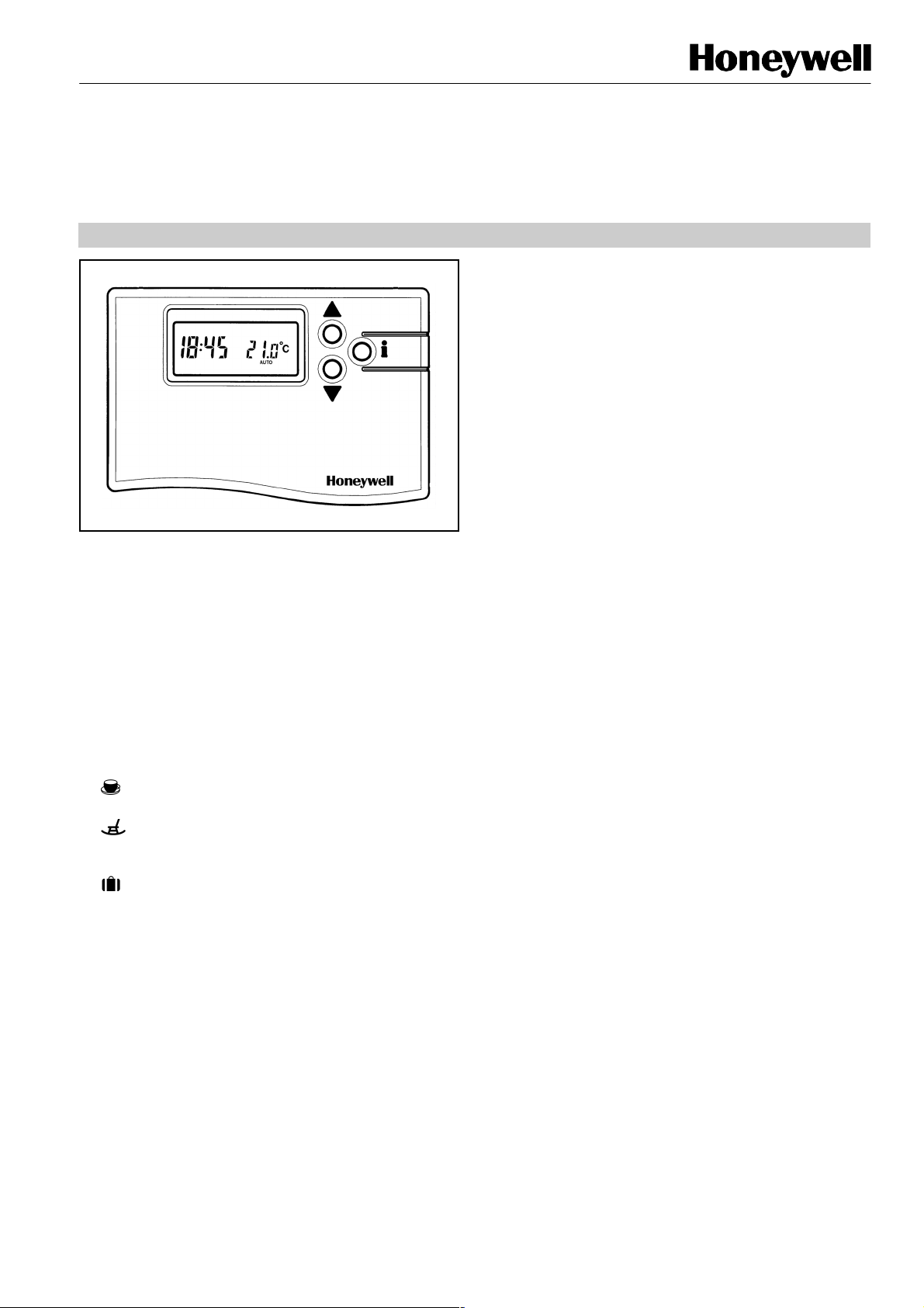
CM67
CHRONOTHERM
PRODUCTSPECIFICATION SHEET
he
M
7 Chronotherm is designed to provide automatic
time and temperature control of heating or cooling systems
in villas and apartments. It can be used as part of a system
in conjunction with combi boilers, oil- burners and gas fired
boilers, circulation pumps, thermal actuators, zone valves
and electric heat systems (<8A).
CM67 is designed with the installer in mind and includes
The
a moulded backplate with trunking guides and wiring
breakouts to make installation quick and easy.
CM67 display, buttons and slider layout are based on
The
the same simple programming philosophy used on the
acclaimed CM51 product. The unit is ideal for consumers
who want reliable precise temperature control from a simple
to program easy to use product.
• Attractive slim styling makes it ideal for location in
any home.
• 7-day program
• 6 daily independent time and temperature level
changes let you set 6 time and temperatures pairs to
suit your life style.
• Temporary programmed temperature override to
temporarily override the programmed temperature
till the next switch point.
• Party button to temporarily maintain (or adjust)
the current temperature for 1-23 hours.
• Day Off button copies Sunday’s program into
tomorrow or today to allow a rest day program
without having to re-program the CM
67.
• Holiday button provides energy savings by
reducing the temperature for 1 to 99 days when
people are on holiday, returning to normal operation
(AUTO or MANUAL) on the day of return.
• EEPROM memory holds the user program
indefinitely.
• Telephone Interface (optional) can be fitted to the
67 to allow switching between programmed mode
CM
(slider position) and fixed set-point of 21
o
C.
• 24...230V 8A resistive, 3A inductive SPDT relay
provides compatibility with most domestic central
heating systems without stocking many different
models.
•
urface or wallbox mounting options, trunking
guides and wiring breakouts simplify installation.
• OFF position on the slider has an integral fixed frost
protection setting at minimum of 5°°°°C (installer
adjustable) so that pipes in the house will never
freeze in winter.
• Installer Set-Up Mode allows extra functions to be
set at the discretion of the installer to match the
consumers applications :
• Optimisation
• Pump Exercise
• Upper / Lower Setpoint Limit Adjust
• Temperature offset
• Minimum ON time
• Cycle rate
• Heat / Cool Operation
• Proportional Band Width
• CM67 has provision for add-on modules to allow the
installer to sell additional features during or after the
first CM
additional sale.
67 installation, giving the installer an
• Outside Temperature Sensor accessory (optional)
can be fitted to the CM
temperature.
67 to display the external
• Remote Temperature Sensor (optional) can be fitted
to the CM
room.
67 to control the temperature from another
EN0R 8498 R2 11/98
Page 2

CM67 CHRONOTHERM
T
c
±
a
CM67 CONTROLS/DISPLAY LAYOUT
SPECIFICATIONS
Batteries : 2 x 1.5 V IEC LR6 (AA) Alkaline cells
Battery life : 4 years typical (Duracell MN1500) for
applications with loads <3A
: 3 years typical for electric heat
applications (>3A, <8A)
Battery
replacement
Switch type : SPDT (potential free)
Electrical rating : 230 V~, 50...60 Hz, 0.5 A to 8 A resistive
Time display : 24 hour or 12 hour AM/PM format
Time keeping
accuracy
Program : 7-day with 6 daily time and temperature
Time setting
resolution
Sensing element : 100K (@ 25
Temperature
setting range
: Program retained in EEPROM
0.5 A to 3 A inductive (0.6 pf)
24 V~, 50...60 Hz, 0.5 A to 8 A resistive
0.5 A to 3 A inductive (0.6 pf)
: Typically better than 10 minutes per year
level changes
: Time of day - 1 minute
Program - 10 minute steps
o
C)NTCthermistor
o
: Program : 5 to 30
Frost : 5
o
Cto16oC). Frost protection does not
(5
Cin0.5oCsteps
o
C or equal to lower limit
work in cooling mode
emperature
ontrol accuracy
Room
:
0.5 K (nominal) @ 20oC, 50% load
3K∆/hour
: From 0
o
Cto40oC
Temperature
display range
Control form
Minimum ON
time
: P + I (Proportional + Integral)
: 10% of cycle time (min one minute),
adjustable to 2 to 5 min (see installer set
up)
Cycle rate
: 3, 6( default), 9, 12. Selectable through
the installer set up mode.
Wiring
: Terminal block capable of accepting
wiresupto2.5mm
2
Wire access : Mains wiring - rear, left or below
Low voltage wiring - rear, left or below
Dimensions
: 130 x 87R(82L) x 29 mm (w x h x d)
130 x 172 x 29 mm (w x h x d) (flap
open)
Environmental
: Operating temperature range 0 to 40
Shipping and storage temperature range
-20to55
o
C
Humidity range 0 to 90% rh, noncondensing
Approvals
: Designed to meet European EN
pprovals EN60730-1(1995), EN55014-1
(1997), EN55014-2 (1996)
o
C
EN0R 8498 R2 11/98 2
Page 3
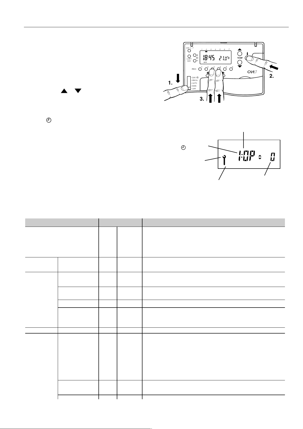
INSTALLER SET-UP
To enter the installer set-up mode :
a) Set the program slider to OFF.
b) Press and hold Info
together.
c) The unit will display the first parameter of the installer
parameter group category 1 (from n.1 to n.5).
d) Press TEMP
display will flash indicating that a change has been
made.
e) Press INFO
i button to confirm the change. The display
will stop flashing.
f) Press
+or-togotonextparameter.
g) Press PROG 2 button to go to Installer parameter group
category 2 (from parameter n.6 to parameter n.16).
h) To exit installer mode move the slider in MAN or AUTO
position.
i button and press PROG 3,4
or to change factory setting. The
Installer Set-upNumber
(Press + or - to change)
e.g. 1 = Optimisation
Installer Set-UpMode
Selected
CM67 CHRONOTHERM
Abbreviated Set-Up Description
e.g. OP = Optimisation
1
In Installer set up we can :
❑ Set-up specific applications
❑ Enable special features
❑ Establish support for Optional Accessories
Specific Applications Setting What do you need to change ?
Heating Gas Boilers
(<30KW)
Oil Boiler 3 4 1. Set Minimum ON Time to 4 m inutes.
Thermal
Actuator
Zone valve 6 1 No action required.
Electric heating
(for applications
<8A)
Cycle/
Hour
Minimum
ON time
(in minutes)
6 1 No action required
12 1 Set Cycle/Hour to 12.
12 1 1. Configure the Chronotherm for electric heating (set parameter
Note :
a. To change Cycle/Hour, please go to parameter n. 9 in the
installer set-up mode.
b. To change Minimum ON Time, please go to parameter n. 2 in
the installer set-up mode.
2. Set Cycle/Hour to 3.
n.7 in the installer set up mode to 1).
2. Set Cycle/Hour to 12.
Factory Setting or New Choice
Press TEMP ▲ or ▼ to change
e.g. O = Optimisation disabled
1 = Optimisation enabled
Air
conditioning
Heat Pump/
Air conditioner
1. For cooling application only, set the Chronotherm to cooling
(set parameter n.6 in the installer set-up mode to 0)
2. For heat/ cool application, set the Chronotherm accordingly to
required mode of operation
winter = heating
summer = cooling
by changing parameter n.6 in the installer set-up mode. Explain to
the end-user how to implement the change-over.
3 4 1. Set Minimum ON Time to 4 minutes .
2. Set Cycle/Hour to 3.
3 EN0R 8498 R2 11/98
Page 4

CM67 CHRONOTHERM
Special Features Description What to do if we wish this
feature
Optimisation (Variable
Start Time)
Adaptive Intelligence
recovery TM
The Chronotherm will adjust the start time in the
morning/ afternoon so the desired temperature is
reached by the start of the program period e.g. Time
7:00, Temp 21
o
C. The Chronotherm will monitor the
Set parameter. 1 in the installer setup mode to 1.
accuracy of the start up and use this information to
modify the calculation for the following day by
changing the ramp rate (initial 3 K/hr) .The system will
restrict the start time to a max of 3 hours.
Optimisation will not work in cooling mode.
AM-PM/ 24hr Display Change display format (default 24hr) Set parameter n.3 in the installer set -
up mode to 1.
Pump exercise When enabled the Pump Exercise will switch the relay
on for 1 minute at 12:00 if the relay has not been
Set parameter n.8 in the installer set up mode to 1.
switched on since 12:00 the previous day.
While in Holiday mode the Pump Exercise feature, if
enabled, will operate.
Upper Temperature
Limit
The normal upper temperature limit of 30oC can be
reduced down to 21
o
C to save energy. Useful for small
Set parameter n.11 in the installer set
-up m ode to the desired limit.
commercial premises.
Lower Temperature
Limit
The normal lower temperature limit of 5oC can be
increasedupto16
o
C to protect the inhabitants from
Set parameter n.12 in the installer set
-up m ode to the desired limit.
cold. Useful if the inhabitants include the elderly,
children or disabled.
Temperature Offset If the Chronotherm is located in a hot/cold location and
cannot be moved because of wiring then the measured/
displayed temperature can be adjusted by +/- 3
o
C.
Set parameter n.13 in the installer set
-up mode to the desired offset value.
Useful if the homeowner wants the reading to match
another appliance temperature display.
Proportional Band Width Can be adjusted up to 3oC (default is 1.5oC) to provide
better temperature control (less overshoot).
Useful for:
a. Well insulated homes with over-sized heating
systems
b. Air systems with fast response
Optional
Description What to do if we wish this
Accessories
OutsideTemperature
Sensor
Remote Temperature
Sensor
Automatic Time Setting
(ATS) Module
An Outside TemperatureSensor can be fitted to your
to allow the homeowner to display the outside
CM67
temperate on the Chronotherm display by using the
i button. CM67
INFO
every 10 minutes. Outside temperature display range is
from -30
o
Cto+45oC. The sensor can be connected up
will read the outside temperature
to 50 meters from the unit.
A Remote Temperature Sensor can be fitted to your
to allow the Chronotherm to control temperature
CM67
from another room or space where it is inconvenient to
locatethe CM67
It will read the remote sensor every 1
minute. The sensor can be connected up to 50 meters
from the unit. Useful for commercial premises where
the public may tamper with the product.
The ATS module picks up a time signal daily from a
European transmitter, so you never need to set or
adjust the time.
Set parameter n.15 in the installer set
-up mode to the desired value.
feature
1. Fit the sensor (instructions
included in the sensor package)
2. Set parameter n. 10 in the
installer set-up mode to 1
1. Fit the sensor (instructions
included in the sensor package)
2. Set parameter n. 10 in the
installer set-up mode to 2
1. Fit the ATS module
2. Set parameter n. 4 in the installer
set-up mode to 1
EN0R 8498 R2 11/98 4
Page 5

CM67 CHRONOTHERM
Parameter Installer Set-
Optimisation 1:0P 0 Optimisation disabled 1 Optimisation enabled 1
MinimumONTime 2:0t 1 1minuteminimumONtime 2to5 2-2minutes
AM-PM / 24hr Display 3:Cl 0 24hr clock display 1 12hrAM/PMclockdisplay 1
Accessory Module Type 4:At 0 No accessory module
RESET Time /
Temperature Program
You must now press the PROG 2 key to enter the next section
Heat / Cool Operation 6:HC 1 Heating Operation 0 Cooling Operation 2
Electric Heat 7:Eh 0 Applications < 3A 1 Applications 3 - 8A 2
Up Number /
Abbreviation
(Press + or key to
change)
5:rP 1 Time / Temperature profile set
Factory Setting Optional Setting InstallerSet-
Display Description Display/Setting Description
3 - 3 minutes
4 - 4 minutes
5 - 5 minutes
plugged in
to factory default
Changes to 0 when one of the
time/temp profiles are changed
1, 2 1 - Auto Time Setting Module
2 - Weatherstation Module
0
1
Time / Temperature are as
programmed
To restore the factory profile
set to 1
Up Category
(Press keys
PROG 1 or 2
to select)
12
1
1
1
Pump Exercise 8:PE 0 PumpExercise Disabled 1 Pump Exercise Enabled 2
Cycle Rate 9:Cr 6 6 cycles perhour(cph) for gas
Second Temperature
Sensor
Upper Temperature Limit 11:UL 30 30°C Upper Temp. Limit 21 to 29 21°C to 29°C adjustment in
Lower Temperature Limit 12:LL 5 5°C Lower Temp. Limit 6 to 16 6°C to 16°C adjustment in
Temperature Offset 13:tO 0 No offset -3 to +3 -3°C to +3°C adjustment in
Pressure Offset
(needed for
Weatherstation accessory
only)
Proportional Band Width 15:Pb 1.5 1.5°C Proportional Band 1.6 to 3.0 1.6°C to 3.0°C adjustment in
Return all Set-Up
Features to Factory
Settings
10:SS 0 Nosensor fitted 1, 2 1 - Outside Temperature
14:PO 0 No offset -99 to +3 -99 mbar to +99 mbar
16:FS 1 Allsettings held are the factory
boilers, zone valves and fancoil
defaults. Changes to 0 when
one of the parameter values
are changed
3, 9, 12 3 - 3 cph
9 - 9cph
12 - 12 cph
Sensorfitted
2 - Remote Temp. Sensor
fitted
1°C steps
1°C steps
0.1°C steps
adjustment in 1 mbar steps
0.1°C steps
0
1
Settings are as modified
above
To restore the factory profile
set to 1
2
2
2
2
2
2
2
2
EN0R 8498 R2 11/985
Page 6

CM67 CHRONOTHERM
w
DIMENSIONS
INSTALLATION
LOCATION
The CM67 Chronotherm is the temperature control element
in the heating/cooling system and MUST be located in a
position with good air circulation at average room
temperature on an inside wall 1.5 metres above the floor
level. Do not position the CM67 Chronotherm near sources
of heat (radiators, hot air vents, TV or lights), near doors or
indows, or in direct sunlight.
MOUNTING
The CM67 Chronotherm can be mounted directly on the wall
surface or on an electrical wallbox.
WIRING
The CM67 Chronotherm is designed for fixed wiring only and
must be installed in accordance with latest l.E.E. regulations.
Ensure the wiring connection to the supply is via a fuse rated
at no more than 8 amps and a Class "A" switch (having
contact separation of at least 3 mm in all poles).
IMPORTANT
1. The installer must be a trained service engineer
2. Disconnect the power supply before beginning
installation
EN0R 8498 R2 11/98 6
Page 7

WIRING
N
CM67 CHRONOTHERM
ORDERING SPECIFICATION
Description Model Logo Literature Spec Sheet
7-day
programmable
thermostat
Remote sensor T7043G1004 Honeywell Multi-
Outsidetemp
sensor
Automatic
Time Setting
Module Europe
Honeywell Control Systems Limited http://europe.hbc.honeywell.com
Newhouse Industrial Estate
Motherwell ML1 5SB
United Kingdom
T6667B1002 Honeywell English ENOR8498
ENOR8496
Language
F42009537-
001
Q6667B1007 Multi-
Multi-
Language
Language
ENOR8495
ENOR8501
OTE: The model shown opposite
can be ordered as samples to
establish the exact
customisation requirements
EN0R 8498 R2 11/98
 Loading...