

Page 1
GB
F
NL
I
SK
1000243906-002-04
D GB I
➔ www.docuthek.com
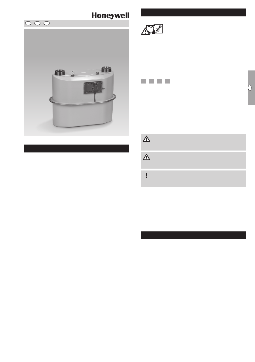
Operating instructions
White meters
BK V to BK V
(component of a diaphragm gas
meter)
© 2017 Elster GmbH · Edition 06.17
Translation from the German
Contents
Contents
White meters BK V to BK V
(component of a diaphragm gas meter) ....
Contents ..............................
Safety.................................
Checking the usage .....................
White meters BK V2 to BK V12 .............2
Type code .............................2
Part designations ........................2
Type label/Marking .......................2
Integrated pressure and temperature
sensor (optional) .......................
Integrated valve (optional)................
Installation ............................
Temperature test point ..................4
Pressure test point on housing (optional) ...4
Connecting the piping ....................4
Pressure test point on outlet connector
(optional) ..............................5
Opening the test nipple ...................5
Closing the test nipple ....................5
Tightness test ..........................5
Commissioning.........................5
Maintenance/Removal...................5
Technical data .........................6
Declaration of conformity ................7
White meters BK V2 – V12 with explosion
protection ............................. 7
White meters BK V2 with explosion
protection and integrated valve Ve...........8
ATEX legend ...........................9
Contact ..............................0
Logistics ..............................9
Safety
Safety
Please read and keep in a safe place
carefully before installing or operating. Following the
installation, pass the instructions on to the operator. This unit must be installed and commissioned
in accordance with the regulations and standards
in force. These instructions can also be found at
www.docuthek.com.
Explanation of symbols
• , , , ... = Action
▷ = Instruction
Liability
We will not be held liable for damage resulting from
non-observance of the instructions and non-compliant use.
Safety instructions
Information that is relevant for safety is indicated in
the instructions as follows:
Please read through these instructions
DANGER
Indicates potentially fatal situations.
WARNING
Indicates possible danger to life and limb.
CAUTION
Indicates possible material damage.
All interventions may only be carried out by qualified
gas technicians. Electrical interventions may only be
carried out by qualified electricians.
Conversion, spare parts
All technical changes are prohibited. Only use OEM
spare parts.
Changes to edition 0.6
The following chapters have been changed:
– Checking the usage
– Integrated valve
– Technical data
– Declaration of conformity
GB-1
Page 2
GB
F
NL
I
SK
Checking the usage
White meters BK V to BK V
White meters are components of diaphragm gas
meters and cannot be operated independently. They
are suitable for recording gas consumption values
for natural gas, town gas, propane and butane,
as gases of the first to third families pursuant to
DINEN437:2003 (DVGWCode of PracticeG260),
and can be extended to form complete diaphragm
gas meters by installing an index.
The following sizes of gas meter can be assembled
from the listed white meters:
Meter Size
BK V G4
BK VS G4, G6
BK V6 G6, G10, G16
BK V G25
Potentially explosive atmosphere
White meters that are marked with and (see
sticker on the base plate) are suitable for operation
in potentially explosive atmospheres, see page7
(Declaration of conformity).
▷
If a pressure/temperature sensor is integrated
in the white meter, this must be included in the
ATEX assessment of the control electronics.
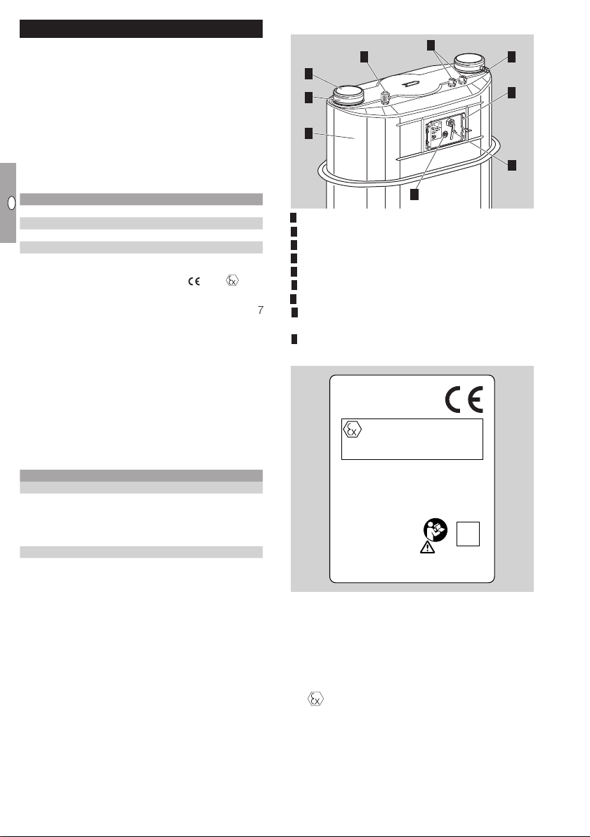
Part designations
7
5
3
1
White meter BK V
Base plate with type label
Connectors
4 Pressure test point to BS4161 (optional)
5 Protective caps
6 2 x thermowells (optional)
7 Pressure test point with sealing sleeve (optional)
8 Connection cable for internal pressure and tem-
perature sensor (optional)
9 Index drive (inner part of the magnetic coupling)
Type label/Marking
6
4
2
8
9
The meter function is only guaranteed when used
under the specified operating conditions– see
page 6 (Technical data). Any other use is considered as non-compliant.
Type code
Code Description
BK V Meter
6
S Increased flow cross-sections
Cyclic volume:
2 dm3
6 dm
12 dm
BK V..
DE–13–EC–PTB001
S/N:0025....
3
3
– Device designation BK V..
– Evaluation certificate No. DE-13...
– Serial number S/N...
– Manufacturer’s address
– Year of construction
White meters with no integrated valve
– CE marking and ATEX identification
ATEX-compliant use is as follows:
Category: internal: none, external: Category 2
(Zone1).
Type of atmosphere: gases, hazes and vapours.
Elster GmbH
Strotheweg 1
D-49504 Lotte
Germany
II -/2 G c IIB TX
TÜV 11 ATEX 090370 X
2017
Valve Ve
GB-2
Page 3
GB
F
NL
I
SK
White meters with integrated valveVe
– CE marking and ATEX identification
II 3 G IIB T4
from the operating instructions for the control
electronics.
▷ Technical data, see page 6 (Technical data).
17 ATEX 1431X
– Valve marking
Installation
Ve = bi-stable valve for electronic flow rate
testing
ATEX-compliant use is as follows:
Category: 3 (Zone2).
Type of atmosphere: gases, hazes and vapours.
WARNING
Please observe the following to ensure that neither
persons nor the meter are damaged during installation and operation:
– Note the max. allowable operating pres-
Integrated pressure and temperature sensor (optional)
As an option, a combined pressure/temperature
sensor of type KP089 made by elgass.r.o. (Czech
Republic) can be integrated in the meter.
In this case, the conductors of the connection cable
are assigned as follows:
surep
page6 (Technical data).
– Note the permitted ambient temperaturetm and
gas temperaturetg, see page6 (Technical
data).
– The white meters are certified for mechanical ambi-
ent conditions pursuant to Class M1 of Directive
2014/32/EU. When installed, the meters must
and measuring rangeQ
max
max
, see
not be subject to permanent vibration such as
1
2
3
4
VCC (voltage supply 2.8 to 3.6V)
SDA (data signal of the I²Cbus)
GND (system ground)
4 SCL (clock signal of the I²Cbus)
Integrated valve (optional)
A valve of type Ve may be integrated in the meter as
an option. This is marked on the type label below the
year of construction with the note “Valve Ve”.
WARNING
Risk of explosion in explosion-hazard areas!
– The intrinsic safety of the control electronics
must be proven.
– When working on electrical equipment in an
explosion-hazard area, only design-approved
electrical operating equipment may be used.
– Check that the electrical system complies with
the special electrical explosion protection requirements.
– Note the permitted connection ratings of the
interfaces. See page 6 (Technical data),
White meters BK V with explosion protection
and integrated valveVe.
▷ A connection cable leads out of the meter.
▷
There is a detailed specification for actuating the
valve and using the interface. Please contact the
manufacturer.
▷
The manufacturer of the control electronics is
responsible for creating the conditions required
commissioning and operation are to be taken
for safe operation of the valve. Instructions on
that caused by machines in the vicinity. In case
of doubt, vibration isolation must be provided.
– When installing meters with integrated valves,
make sure that no dirt particles get into the
meter and thus into the valve.
– The yellow sealing sleeve protects the pressure
test point on the meter. It may only be opened
for connecting a pressure measuring line.
– Use seals made from tested materials. Elasto-
mer seals or asbestos-free flat seals from Elster
are recommended.
– Only use the seals once.
– For meters resistant to high temperatures, only use
seals tested to be resistant to high temperatures.
– For installation and operation, note the applica-
ble national regulations and the directives of the
gas supply company. For Germany, the valid
DVGW Code of Practice G600 (DVGW-TRGI)
applies.
–
Work on meters and the installation of meters which
are marked with and are installed in potentially
explosive atmospheres may only be carried out by
persons with appropriate qualifications.
– The meter marked with must be included in
the equipotential bond when being installed in a
potentially explosive atmosphere, e.g. by connect-
ing it to a grounded pipeline. Installation must be
carried out in accordance with EN60079-14.
– The meter marked with must be protected
from falling parts.
– Avoid subjecting the unit to mechanical stress
and prevent damage. Gas meters must be in-
stalled without any mechanical stress, preferably
only by suspending them on the connectors.
When using additional clamps, it must be en-
sured that no lateral forces act on the gas meter.
These can be avoided by using flexible or supple
connection lines, for instance.
GB-3
Page 4

GB
F
NL
I
SK
▷ If the meter is stored outdoors, protect the site
1 2
1
2
3
4
5
against rain.
▷
If the drive area (magnetic coupling) is protected
against the ingress of moisture by an index, then
the meter is also suitable for outdoor installation.
Remove protective caps.
▷
Installation in the vertical position: connectors
must be pointing upwards.
▷ Note direction of flow (arrow).
▷
After installation, the completed gas meter must
not be in contact with masonry or other parts.
▷ Ensure that there is sufficient installation space.
▷
The seal faces on the screw unions must be
clean and damage-free.
▷ Ensure that the seal is correctly seated.
▷ For the compression of seals and the resulting
tightening torques for the screw unions, the seal
manufacturers’ specifications must be observed.
Tightening torques for the recommended flat
seals in conjunction with screw connectors
pursuant to DIN 3376-1 and 3376-2, see
www.docuthek.com → Elster-Instromet → Prod-
ucts → Gas measuring devices → Diaphragm
meters → Ergänzung für Betriebsanleitung BK,
Verschraubungen und Anzugsmomente für BKG1,6 bis BK-G25 (Supplement to BK operating
instructions, Screw unions and tightening torques forBK-G1.6 toBK-G25)(D).
Install the meter free of mechanical stress.
Pressure test point on housing (optional)
Connecting the piping
WARNING
In order to ensure that the meter is tight:
– The pressure test nipple must not be twisted,
bent, or otherwise manipulated.
– When installing, always secure the pressure test
nipple using a suitable spanner.
▷
Functional safety and reliability are ensured only if
the material combination of the screw connector
and the pressure line are inter-matched.
▷
Only use the olive and the attached union nut
supplied. The olive is secured to the sealing
sleeve.
▷
When re-ordering, use original Parker EO progressive ring fittings PSR/DPR.
1
2
3
Temperature test point
▷
Temperature sensors can be inserted into the
thermowells for measuring the gas temperature
in the meter housing.
Secure each of the temperature sensors using
the capstan screw provided.
4
▷
Use corrosion-resistant, seamless precision steel
5
tube pursuant to DINEN10305-4 (external diameter 6mm, material E235= 1.0308). For other
materials, use a suitable adapter and note the
Parker/EO recommendations.
▷ Install pipes free of mechanical stress.
6
7
8 Screw on the union nut by hand as far as it will
go.
▷
At the same time, press the end of the pipe firmly
against the stop.
9 Mark the position of the union nut and tighten
with about 1½ turns.
GB-4
Page 5

GB
F
NL
I
SK
1
6
7
2
3
4
5
▷
2
2
2
When reinstalling, the union nut will be turned to
the original position and then further tightened
through approx. 30°.
0 Once the installation and tightness test are com-
plete, see page5 (Tightness test), protect the
pressure test point against external access with
the sealing sleeve and the seal.
▷ If a pressure measuring line has been retrofitted
to the meter, check this connection for tightness.
Pressure test point on outlet connector (optional)
BS4161-compliant pressure test nipple
▷
Use a 10 mm spanner to release/tighten the
test point screw.
▷
The test nipple is secured to prevent it turning
with the screw.
▷
If the BS4161-compliant test nipple on the meter
has been opened and then closed again, test
this connection for tightness.
After the tightness test, slowly vent the meter.
4 If a pressure measuring line has been retrofitted to
the meter, protect the pressure test point against
external access with a sealing sleeve and a seal.
Opening the test nipple
Remove the screw from the test nipple com-
pletely.
▷ The gas connection is open.
Closing the test nipple
Insert the screw by hand as far as possible.
Tighten the screw with a torque of 3 Nm +
Commissioning
Once the tightness test has been successfully completed, the meter is ready for operation. Where applicable, further instructions are required for a fitted
index.
▷ Slowly open the manual valve.
0.5Nm.
Check for tightness, see page 5 (Tightness
test).
WARNING
If the test nipple has unexpectedly come loose,
the gas meter must be regarded as damaged and
must be replaced.
Maintenance/Removal
Meters BKV2 to BKV12 from Elster are maintenance-free. Where applicable, further maintenance
instructions are to be observed for a fitted index.
▷
If the screw unions are loosened for maintenance
work or retesting, replace the seals.
▷ After the meter has been removed, immediately
Tightness test
▷
Check the pipework for leaks prior to installation
of the meter, in case the pipework is tested with
a greater test pressure than the max. allowable
operating pressure p
the installed meter may be damaged.
for the meter. Otherwise,
max
▷ Ensure the customer’s consumers are closed.
Apply the test pressure slowly to the meter.
close the connectors with protective caps in
order to prevent ingress of dirt particles.
WARNING
A certain amount of gas may remain in the meter.
Taking into consideration the risk of explosion, it is
important to adopt safety measures, e.g.:
– Following removal of the meter, purge it thor-
oughly with inert gas.
– For transporting the meter with gas residue, use
a vehicle with an open or a ventilated loading
area.
GB-5
Page 6

GB
F
NL
I
SK
Technical data
Gas type: natural gas, town gas, propane and
butane, as gases of the first to third families
pursuant to DINEN437:2003 (DVGW Code of
PracticeG260).
– Note the max. allowable operating pres-
sure p
(non-HTR)
▷ HTR: high temperature resistance pursuant to
EN1359:1998+A1:2006, section 6.5.5
– Measuring range (in accordance with Evalua-
tion certificate DE-13-EC-PTB001):
Type Q
BK V2 0.04 / 6
BK V2S 0.04 / 6
BK V2S 0.06 / 10
BK V6 0.06 / 10
BK V6 0.06 / 16
BK V6 0.10 / 16
BK V6 0.10 / 25
BK V6 0.16 / 25
BK V12 0.25 / 40
– Max. allowable ambient temperature range
tm=-25°C to +55°C
– Max. allowable gas temperature range
tg* = -25°C to +55°C
– Cyclic volume V
BK V2, BK V2S: V = 2 dm³
BK V6: V = 6 dm³
BK V12: V = 12 dm³
– Transitional flow rate Qt = 0.1 x Q
– Max. allowable storage temperature range:
-25°C to +60°C
– Mechanical environment class: M1
= 0.1 bar (HTR version)/0.5 bar
max
min/Qmax
in m³/h
max
White meters BK V with pressure test point
Pressure test point: 24° olive fitting to
ENISO8434-1, L6x M12x1.5-St.
White meters BK V with integrated valve Ve
Max. operating pressure for valve operation:
100mbar.
▷ The operating pressure of the gas meter can be
higher if necessary.
Leakage flow (closed): max. 1 l/h up to 100 mbar.
White meters BK V with explosion protection
and integrated valveVe
For meters of Category3 which are marked with ,
the ambient temperature t
ture t
are limited to a maximum range between
gas
-20°C and +55°C.
and the gas tempera-
amb
In addition, the following interface parameters apply
for BKV:
Ui = 4.1 V
Ci = negligible
Li = 3.82 mH
Supplementary notes:
* If operated within the gas temperature range,
the measuring error still lies within the required
error limits.
GB-6
Page 7

GB
F
NL
I
SK
Declaration of conformity
Scan of the Declarations of conformity – see www.docuthek.com → Elster-Instromet
White meters BK V – V with explosion protection
GB-7
Page 8

GB
F
NL
I
SK
White meters BK V with explosion protection and integrated valve Ve
GB-8
Page 9

GB
F
NL
I
SK
ATEX legend
= Marking of explosion protection
II = Equipment group ll for general industries
(with the exception of mines)
-/2 = Category:
internal: none
external: Category 2 (Zone 1)
3 = Category 3 (Zone 2)
G = Type of atmosphere: gases, hazes and
vapours
c = “Constructional safety” explosion protection
type
IIB = Explosion group for gases
TX = No intrinsic heating
T4 = Temperature class: maximum allowable
surface temperature 135°C
Logistics
Transport
Diaphragm gas meters are always to be transported
in the upright position. On receipt of the product,
check that the delivery is complete, see page 2
(Part designations). Report any transport damage
immediately.
Storage
Diaphragm gas meters are always to be stored in the
upright position and in a dry place. Ambient tempera-
ture: see page 6 (Technical data).
Disposal
Components are to be disposed of separately.
On request, old units may be returned carriage paid
to the manufacturer, see page 10 (Contact), in
accordance with the relevant waste legislation re-
quirements.
GB-9
Page 10

GB
F
NL
I
SK
Contact
Contact
United Kingdom
Elster Metering Limited
Paton Drive
Tollgate Business Park
Beaconside
Stafford, ST16 3EF
T +44 1785 275200
F +44 1785 275305
jeavons.info@gb.elster.com
www.elstermetering.co.uk
Germany
Elster GmbH
Strotheweg 1
49504 Lotte
T +49 541 1214-0
F +49 541 1214-370
info@elster-instromet.com
www.elster-instromet.com
Ireland
Active Energy Control Ltd.
Unit 4, Clare Marts
Quin Road
Ennis, Co. Clare
T +353 65 6840600
F +353 65 6840610
info@aec.ie
www.aec.ie
GB-10
in the interests of progress.
We reserve the right to make technical modifications
 Loading...