

Page 1

AGA
Burner control unit BCU 370
Technical Information · GB
6 Edition 01.19
• For modulating, forced draught burners for gas of unlimited
capacity in intermittent or continuous operation
• Control of fan and butterfly valve
• Simple system set-up thanks to optional tightness control and
integrated ignition unit
• Easy start-up and maintenance thanks to Manual operating mode
• Optionally available with integrated fieldbus interface for simple
wiring
Page 2

Contents
Burner control unit BCU 370 ........................1
Contents ............................................2
1 Application ........................................4
1.1 Applications example ..............................6
1.1.1 Modulating-controlled forced draught burner........6
1.1.2 Modulating-controlled forced draught burner with
tightness control ............................................6
1.1.3 Modulating-controlled forced draught burner with
pilot burner and tightness control ..........................7
1.1.4 Controlling the BCU via
PROFIBUS DP ...............................................8
1.1.5 Controlling the BCU and the butterfly valve via
PROFIBUS DP ...............................................8
2 Certification .......................................9
3 Function ......................................... 10
3.1 Connection diagrams .............................10
3.1.1 BCU 370 . . . . . . . . . . . . . . . . . . . . . . . . . . . . . . . . . . . . . . . . . . . . . 10
3.1.2 BCU 370 with actuator IC 20........................ 14
3.1.3 Capacit y control by adjusting the valve between
the Open position and a separate Min position........... 15
3.1.4 BCU 370..B1 with PROFIBUS DP ...................16
3.1.5 Assignment of connection terminals ................17
3.2 BCU 370 program sequence .....................19
3.2.1 Normal start-up ..................................... 19
3.2.2 Quick start, butterfly valve waits in the Ignition
position.....................................................21
3.2.3 Quick start, butterfly valve waits in the Closed
position....................................................23
3.2.4 Start-up without pre-purge, butterfly valve waits
in the Closed position ..................................... 25
3.2.5 Controlled air flow ....................................27
3.3 Tightness control .................................28
3.3.1 Program sequence ..................................30
3.4 PROFIBUS DP ....................................32
3.4.1 Safety-related control signals.......................32
3.4.2 BCSoft ...............................................33
3.4.3 Configuration, master-slave procedure .............33
3.4.4 Addressing...........................................33
3.4.5 Network technology .................................34
3.4.6 Configuration........................................34
3.4.7 Bus communication .................................34
3.5 Program status ...................................36
3.6 Fault message (blinking)..........................37
3.6.1 Reaction to process faults ..........................38
4 Parameters ...................................... 40
4.1 Scanning the parameters .........................42
4.2 Flame control . . . . . . . . . . . . . . . . . . . . . . . . . . . . . . . . . . . . . 42
4.2.1 Burner flame signal.................................. 42
4.2.2 Burner switch-off threshold......................... 42
4.2.3 UVS check (1× in 24 hours) ..........................43
4.3 Behaviour during star t-up ....................... 44
4.3.1 Minimum burner pause time tBP ....................44
4.3.2 Burner start-up attempts ...........................44
4.3.3 Switch-on delay time t
4.3.4 Pre-ignition time t
st
4.3.5 1
t
SA1
4.3.6 1
4.3.7 2
4.3.8 2
safety time on start-up, burner/pilot burner
........................................................46
st
flame proving period, burner/pilot burner t
nd
safety time on start-up, main burner t
nd
flame proving period, main burner t
.............................45
E
................................45
VZ
FS1
.......47
SA2
.........47
FS2
..46
4.4 Behaviour during operation...................... 48
4.4.1 Minimum operating time tB .........................48
4.4.2 Controller enable signal delay time t
4.4.3 Safety time during operation t
SB
.............48
RF
...................48
4.4.4 Restart after flame failure during operation ........49
4.4.5 Last fault signal .....................................49
4.4.6 V2 during burner operation .........................50
4.5 Monitoring/tightness control ....................51
4.5.1 Min. gas pressure monitoring ........................51
4.5.2 Digital input function.................................51
4.5.3 Air monitoring during pre-purge .................... 52
4.5.4 Air monitoring during operation.....................53
4.5.5 Tightness controll, test period t
...................54
P
BCU 370 · Edition 01.19 2
= To be continued
▼
Page 3

4.6 Air control .........................................56
4.6.1 Valve control .........................................56
4.6.2 Pre-purge............................................56
4.6.3 Quick start starts in... .................................57
4.6.4 Pre-purge time t
4.6.5 Post-purge time t
4.6.6 Fan run-up time t
. . . . . . . . . . . . . . . . . . . . . . . . . . . . . . . . . . 58
PV
.................................59
PN
.................................60
GV
4.7 Control using PROFIBUS DP .....................61
4.7.1 Bus control activation ................................61
4.7.2 Bus control limitation.................................61
4.8 Manual mode .....................................63
4.8.1 Operating time in Manual mode ....................63
4.9 Fault messages ...................................64
4.9.1 The last 10 fault messages..........................64
4.10 Password ........................................64
4.10.1 User-defined password . . . . . . . . . . . . . . . . . . . . . . . . . . . . 64
5 Selection ........................................ 65
5.1 Type code .........................................65
6 Project planning information .................... 66
6.1 Cable selection .................................. 66
6.1.1 Ionization cable......................................66
6.1.2 UV cable .............................................66
6.1.3 Ignition cable ........................................66
6.2 Fan control........................................67
6.3 Controlling the butterfly valve ....................67
6.4 Safety interlock (limits) ...........................67
6.5 Too many remote resets ..........................67
6.6 Protecting the ignition unit from overload ...... 68
6.7 Wiring ............................................ 68
6.7.1 Single-electrode operation with external ignition
unit.........................................................68
6.8 BCU switched off ................................ 68
6.9 Note on EC type-examination or CSA and FM
approval ...............................................69
6.10 Contact fuses ...................................69
6.11 Installation ......................................69
6.12 Protective circuits . . . . . . . . . . . . . . . . . . . . . . . . . . . . . . .69
6.13 BCSoft...........................................69
7 Flame control ..................................... 70
7.1 ...with flame rod....................................70
7.2 ...with UV sensor ...................................70
8 Accessories.......................................71
8.1 High-voltage cable ...............................71
8.2 BCSoft ............................................71
8.2.1 Opto-adapter PCO 200 ..............................71
8.3 Radio interference suppressed terminal boots...71
8.4 Connection kit BCU 370..........................71
8.5 Set of stickers BCU 370...........................71
8.6 GSD master data file for BCU 370..B1 ............72
9 Technical data ....................................73
9.1 PROFIBUS DP ....................................74
9.2 Operating controls and dimensions ..............75
9.3 Converting units ..................................76
10 Legend ..........................................77
11 Glossary .........................................78
11.1 Safety shut-down ................................78
11.2 Fault lock-out....................................78
11.3 Warning signal ...................................78
11.4 Timeout 25 s/250 s .............................78
12 Annex .......................................... 79
12.1 Status and fault messages for PROFIBUS DP ..79
Feedback ...........................................82
Contact.............................................82
BCU 370 · Edition 01.19 3
= To be continued
▼
Page 4

Application
BCU 370
1 Application
The BCU 370 burner control unit controls, ignites and
monitors industrial forced draught burners of unlimited
capacity in intermittent or continuous operation.
It can be used for directly ignited forced draught burn-
ers or forced draught burners ignited with pilot burner.
The BCU 370 activates the fan and sets the connected
butterfly valve to Pre-purge and Ignition position. After
pre-purge and burner start, the enable signal is issued
to an external controller which positions the butterfly
valve in accordance with the capacit y demand. Post-
purge occurs after the end of burner operation. The
burner control unit BCU 370 monitors the gas and air
pressure. An optionally integrated tightness control
BCU 370 · Edition 01.19 4
Lower section Upper section
function checks the valves with an external gas pres-
sure switch.
Programmability by means of the optical interface and
BCSoft PC software guarantees optimum adaptation to
the relevant application. Adjustable start-up attempts
and automatic restart which can be activated ensure
the high flexibility of the burner equipment.
The quick-start option allows standard-compliant star t-
up of the forced draught burner without pre-purge
after controlled shut-down. This avoids unnecessary
admission of air into the combustion chamber. The heat
output is available as quickly as possible after a temperature demand.
▼
Page 5

Application
The program status, the unit parameters and the level
of the flame signal can be read directly from the BCU.
An integrated Manual mode allows manual start of the
burner and setting of the butterfly valve position inde-
pendently of the central control system. The BCSoft
operator-control and setting software provides a pow-
erful tool for commissioning and servicing.
To reduce the installation and wiring costs, Honeywell
Kromschröder offers an optional Profibus DP interface
to transfer the activation signals and feedbacks.
BCU 370 · Edition 01.19 5
Page 6

Application
L1
L1
21
24
23
22
DG
DG
21
24
23
22
DG
DG
BCU 370..I1
9 3
7
min
DL
VG
BCU 370..I1..D3
9 3
7
min
DL
VG
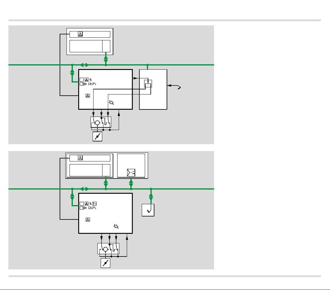
1.1 Applications example
25
28
26
20
19
90° ➔ 0
4
V1
VG..L
DG
DG
VG..L
VG..L
IC 20
11
11
IC 20
DL
4
4
V1
V1
DG
DG
pu/2
pu/2
DL
0 ➔ 90°
5293130 32
V2
M
BVA
0 ➔ 90°
29 3130
5 32
5
V2
V2
M
B VA
GIK
90° ➔ 0
GIK
18
17
13
UVS
25
28
26
20
19
18
17
13
UVS
1.1.1
Modulating-controlled forced
draught burner
The BCU 370 controls the fan and
moves the butterfly valve to prepurge and ignition position. It issues
the enable signal to the control system after start-up of the burner.
Modulating-controlled forced
1.1.2
draught burner with tightness
control
In addition to controlling the forced
draught burner, the burner control
unit also monitors the fail-safe
function of the two solenoid valves
for gas via the gas pressure switch
DG which is set to pu/2.
Parameter 27 = 1: V2 is “ON” during
burner operation.
BCU 370 · Edition 01.19 6
Page 7

Application
L1
21
24
23
22
DG
DG
BCU 370..D3
9 3
7
min
DL
VG
V1 V2
DL
45
DG
pu/2
11
DG
VG..L
VG
IC 20
BVA
90° ➔ 0
0 ➔ 90°
29 3130
632
V3
M
GIK
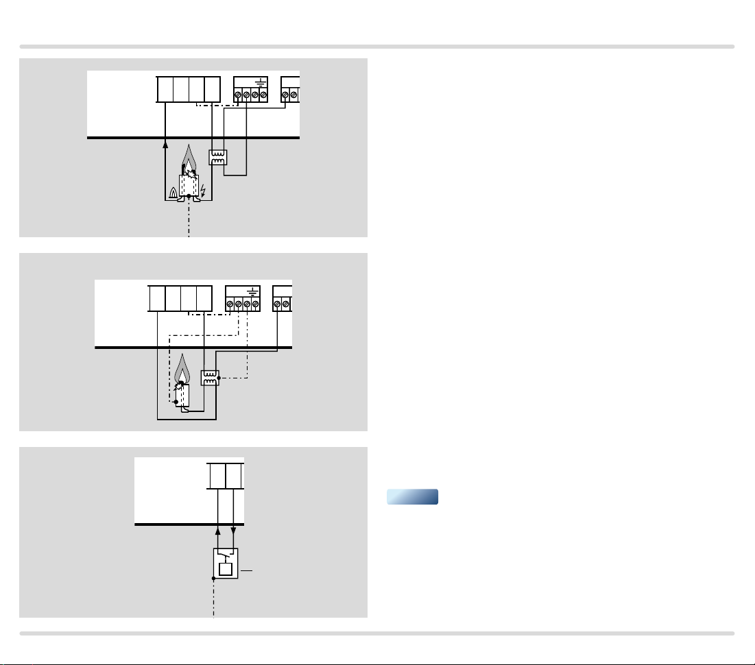
1.1.3
25
28
26
20
19
18
17
13
Modulating-controlled forced draught burner with pilot burner and tightness control
A pilot burner ignites the main burner and is switched off during the
main burner’s safety time.
Parameter 27 = 0: V2 is “OFF”, i.e. interrupted pilot burner, during burner
operation.
UVS
BCU 370 · Edition 01.19 7
Page 8
Application
L1,
PLC
BCU 370..B1
ϑ
L1,
L1,
PLC
Profibus DP
BCU 370..B1-3
ϑ
L1,
0 ➔ 90°
29 31 3230
M
3PS
29 30 31
BUS
90° ➔ 0
BUS
0 ➔ 90°
Profibus DP
Temperature
controller
90° ➔ 0
25
28
26
32
3PS
Temperature
controller
ϑ
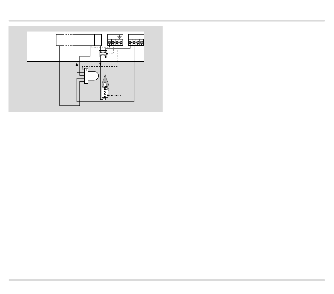
1.1.4 Controlling the BCU via PROFIBUS DP
The BCU 370..B1 issues the enable
signal to the temperature controller
for capacity control. The temperature controller then controls the
butterfly valve directly.
ϑ
1.1.5 Controlling the BCU and the
butterfly valve via PROFIBUS DP
The BCU 370..B13 receives posi-
tioning information for the butterfly
valve from the temperature controller via the PROFIBUS DP and activates the butterfly valve following
controller enable.
M
BCU 370 · Edition 01.19 8
Page 9

Certification
2 Certification
Certificates – see ww w.docuthek.com
EU certified pursuant to
Directive:
– Low Voltage Directive (2014/35/EU),
– EMC Directive (2014/30/EU).
Regulation:
– Gas Appliances Regulation (EU) 2016/426
FM approved
Factory Mutual Research Class: 7611 “Combustion
Safeguards and Flame Sensing Systems”. Suitable for
applications pursuant to NFPA 86.
www.approvalguide.com
ANSI/CSA approved
UL listed
USA and Canada
Underwriters Laboratories – UL 372 “Primary Safety
Controls for Gas and Oil-fired Appliances”.
ww w.ul.com ➔ Tools (at the bottom of the page) ➔ Online Certifications Directory
AGA approved
AGA
Australian Gas Association, Approval No.: 6880
http://ww w.aga.asn.au/product _directory
Eurasian Customs Union
The product BCU 370 meets the technical specifica-
tions of the Eurasian Customs Union.
American National Standards Institute/Canadian
Standards Association – Class number: 333501 and
333581.
BCU 370 · Edition 01.19 9
Page 10

Function
BCU 370..I1
F1
F3
l v1 v2s1v3 cc
31 2 4 5 6 7 8 9 10 11 12 13 14 15 16 1917 18 20 21 22 23 24 25 26 27 28 29 30 31 32
V1 C S1 S L A Z M V2 V3 R
C
V1
V2
DL DG
V3
ppp
minDGmax
230V~
PE N
Z
I
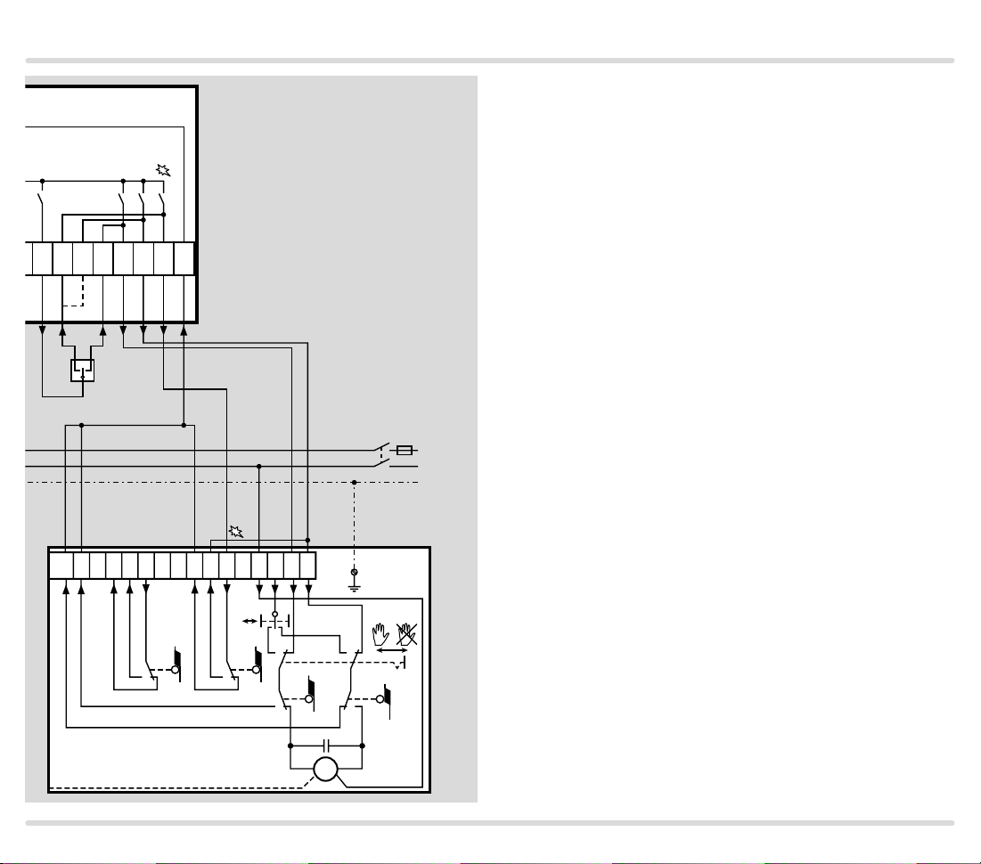
3 Function
3.1 Connection diagrams
3.1.1 BCU 370
The drawing shows the BCU 370..I1 with integrated
ignition unit, ionization control and double-electrode
operation.
For cable selection and wiring, see page 66 (Project
planning information).
90° ➔ 0
0 ➔ 90°
r
r1 s
max. 1 A,
max. 1 A,
253 V
253 V
M
3PS
ϑ
For the explanation of symbols, see page 77 (Legend).
▼
L1 (L1)
N (L2)
PE
BCU 370 · Edition 01.19 10
Page 11

Function
13 14 15 16 PE
3
2
UVS
1
BCU 370..I1 for 120 V and 230 V, UV control
BCU 370..I2
N13 14 15 16 PE
3
2
UVS
1
Z Z
BCU 370..I2 for 230 V, ignition by electrode to electrode
BCU 370..I3 for 120 V, ignition by electrode to electrode
BCU 370..I3
N13 14 15 16 PE
with centre tap for secondary grounding
▼
3
2
UVS
1
BCU 370 · Edition 01.19 11
Z Z
Page 12
Function
BCU 370
BCU 370
BCU 370 with external ignition transformer, e.g. TZI or
N13 14 15 16 PE
Z
I
TGI
BCU 370 with single-electrode operation, which requires an external ignition transformer TZI or TGI
N13 14 15 16 PE
BCU 370..D3, gas pressure switch DG for tightness
BCU 370..D3
11 12
control
▼
p
e
p
2
DG
BCU 370 · Edition 01.19 12
Page 13
Function
BCU 370..U1
131141516 PE N
4
3
UVC 1
2
1
BCU 370..U1 with UV flame detector UVC 1 for continuous operation
Use 5-core connection cable including a PE wire and
complying with local regulations.
The UVC 1 is grounded using a PE wire connection
which is galvanically connected to the housing.
BCU 370 · Edition 01.19 13
Page 14
Function
BCU 370
90° ➔ 0
0 ➔ 90°
r
25 26 27 28 29 30 31 32
3PS
0
90°
16
3.1.2 BCU 370 with actuator IC 20
The “closed contact” (90° ➔ 0) of the external three-
point step controller (3PS) can be connected to terminal 26 or 27.
Terminal 26: the controller operates between the open
and ignition positions.
Terminal 27: the controller operates between the open
and closed positions.
L1 (L1)
N (L2)
PE
90° ➔ 0
0 ➔ 90°
321
674812 1115 13
S11
PE
IC 20
S10
S1S2
S3 S4
M
BCU 370 · Edition 01.19 14
Page 15

Function
90° ➔ 0
0 ➔ 90°
r
25 26 27 28 29 30 31 32
3.1.3 Capacity control by adjusting the valve between the Open position and a separate Min position
This connection is used if the valve position to be ap-
proached is below the Ignition position.
Standard wiring of BCU 370 and BCU 370..B1 without
three-point step control function
Valve position Activation of terminal
Upper end position Open 28
Lower end position Closed 27
Lower end position Min Via separate limit switch
Lower end position Ignition 26
–+
3PS
BCU 370 · Edition 01.19 15
M
Min
Page 16

Function
BCU 370..I1..B1
F1
F3
l v1 v2s1v3 cc
31 2 4 5 6 7 8 9 10 11 12 13 14 15 16 24 25 26 27 28 29 30 31 32
V1 C S1 S L A Z M V2 V3 R
C
V1
V2
DL DG
V3
ppp
minDGmax
r
230V~
PE N
Z
I
3PS
BCU 370..B1
ON
OFF
2B 2A 1B 1A
0 ➔ 90°
M
90° ➔ 0
L1 (L1)
N (L2)
PE
PROFIBUS-DP
3.1.4 BCU 370..B1 with PROFIBUS DP
Function, see page 32 (PROFIBUS DP)
For cable selection and wiring, see page 66 (Project
planning information).
For the explanation of symbols, see page 77 (Legend).
BCU 370 · Edition 01.19 16
Page 17

Function
3.1.5 Assignment of connection terminals
Terminal Type Designation Function
1, 2 V AC input Supply voltage
3 V AC output Fan Connection for fan control
4
5 Gas valve V2 Connection of phase for gas valve V2
6 Gas valve V3 Connection of phase for gas valve V3
7
9 Minimum gas pressure Connection for pressure switch to monitor the minimum gas pressure
11 Maximum gas pressure Connection for pressure switch to monitor the maximum gas pressure
8, 10 and
12
Safety circuit
output
Inputs for
pressure switches
V AC outputs Mains supply Phase for pressure switch mains supply
13
14 Supply voltage to UV sensor Output for supply voltage to UV sensor
15 Burner ground Burner ground input for UV sensor
Flame control
Gas valve V1 Connection of phase for gas valve V1
Minimum air pressure Connection for pressure switch to monitor the minimum air pressure
Flame amplifier input Input for flame amplifier
16 Ignition transformer output Output for (external) ignition transformer
17, 18
19, 20
1) 2)
21
1) 2)
22
1) 2)
23
1) 2)
Floating contact
1) 2)
V AC input
Signalling contact for operating
signals
Signalling contact for faults Contact between terminals 19 and 20 closes in the event of a BCU fault signal
Start-up signal Signal applied: BCU start; no signal: BCU stop
Controlled air flow
Remote reset Input for external signal (button) to reset the unit af ter a fault lock-out
24 Controller enable/emergency stop Connection for higher-level safety devices and interlocks (e.g. emergency stop)
25
26
27
28
2)
2)
2)
2)
Connection for
external threepoint step
controller
Controller enable
Y (to ignition position) Connection for the signal to activate the ignition position
Y (to min. position) Connection for the signal to activate the position for minimum capacity
Y+ (to max. position) Connection for the signal to activate the position for maximum capacity
Voltage to operate the BCU,
1 = phase (L1), 2 = neutral conductor (N)
Contact between terminals 17 and 18 closes once the operating signal has been
received from the burner
Signal applied: fan is started to supply air to the combustion chamber for cooling, for
example. Only functional in standby. The function is deactivated as soon as a signal is
received at terminal 1 (BCU star t).
Output signal for controller enable for the three-point step controller. The actuator can
be set to various positions.
▼
BCU 370 · Edition 01.19 17
Page 18

Function
Terminal Type Designation Function
29, 30
and 31
32 Safety circuit input
1)
BCU..B1: not fitted/non-functional
2)
BCU..B13: not fitted/non-functional
V AC output Capacity control Connection for capacity control using an actuator
Feedback from actuator/
frequency converter
Connection for the position feedback signal from the actuator
BCU 370 · Edition 01.19 18
Page 19

Function
3.2 BCU 370 program sequence
Switch on BCU 370
In the event of fault signal: reset
00
H0
H0
01
A1
P1
A2
03
04
05
Start-up position/standby
Start-up with ϑ signal
Switch-on delay time t
Fan run up time t
Butterfly valve moves to Open position
Pre-purge time t
Butterfly valve moves to Ignition position
Pre-ignition time t
Ignition activated
Safety time t
burner/pilot burner (P12),
Flame proving period t
running for burner/pilot burner (P13)
PV
SA1
V1 and V2 open
running (P22)
E
(P20)
GV
running (P18)
running (P21)
VZ
running for
FS1
3.2.1 Normal start-up
If a fault from the preceding operating cycle is still being signalled after
switching on, it will be necessary
to reset this first. Once the startup signal (ϑ) has been applied, the
switch-on delay tE starts to elapse.
During the fan run-up time t
GV
which follows, the fan starts with
the butterfly valve being closed. The
butterfly valve then moves from the
Closed to the Open position. After
pre-purge, it moves back to the Ignition position.
The running times depend on the
respective actuator. The BCU waits
for actuator feedback before continuing the program sequence.
Now the BCU activates pre-ignition
t
and then opens valves V1 and
VZ
V2 for the pilot burner. The ignition
time tZ is constant.
After the flame proving period for
the pilot burner t
to ignite the main burner.
, valve V3 opens
FS1
▼
BCU 370 · Edition 01.19 19
Page 20

04
05
03
Flame proving period t
FS1
running for burner/pilot burner (P13)
Safety time t
SA1
running for
burner/pilot burner (P12),
V1 and V2 open
Pre-ignition time t
VZ
running (P21)
Ignition activated
Function
06
07
H8
08
08
P9
A0
Safety time t
Controller enabler signal delay time t
Butterfly valve moves to Closed position
SA2
If parameter P27 = 0:
V2 is switched off
Flame proving period t
running for main burner (P15)
Controller enable signal
Controlled shut-down
Post-purge time t
running for main burner (P14),
V3 opens
FS2
(P29)
RF
via ϑ signal
running (P19)
PN
If parameter 27 = 0, V2 closes at the
end of the main burner safety time
t
. The pilot burner is switched off.
SA2
Then the flame proving period for
the main burner t
and the con-
FS2
troller enable signal delay time tRF
start to elapse. Af terwards, the BCU
issues the enable signal to the controller.
If there is no pilot burner, program
steps
06
and
07
will be omitted.
As soon as the start-up signal (ϑ) is
switched off, post-purge starts. The
butterfly valve moves to the Ignition position during this time, then
to the Closed position. Next, the
BCU rests in the start-up position/
standby.
00
BCU 370 · Edition 01.19 20
Start-up position/standby
Page 21

Function
00
H0
H0
01
02
03
04
05
06
Start-up position/standby
Start-up with ϑ signal
Switch-on delay time t
Fan run up time tGV (P20)
Waiting time t
Pre-ignition time t
Ignition activated
Safety time t
burner/pilot burner (P12),
V1 and V2 open
Flame proving period t
running for burner/pilot burner (P13)
Safety time t
running for main burner (P14),
SA2
V3 opens
running (P22)
E
running (P21)
VZ
running for
SA1
3.2.2 Quick start, butterfly valve
waits in the Ignition position
Parameter 06 = 0, parameter 28 = 0
Quick start is the same as normal
start, except that pre-purge is
dispensed with. The burner starts
quicker. This results in improved
control quality, since there is no
dead time, the energy is used better
and no cold air is fed to the combustion chamber.
The BCU 370 only carries out a
W
quick start if the last shut-down
was a controlled shut-down. No
more than 24 hours may have
elapsed and the BCU must have
been switched on.
In contrast to the “normal start-up”,
in the case of a quick start, program
A1
FS1
steps
ted.
P1
,
and
A2
will be omit-
If there is no pilot burner, program
steps
06
und
07
will also be omit-
ted.
If parameter P27 = 0:
V2 is switched off
BCU 370 · Edition 01.19 21
▼
Page 22

05
06
04
03
Flame proving period t
FS1
running for burner/pilot burner (P13)
Safety time t
SA2
running for main burner (P14),
V3 opens
If parameter P27 = 0:
V2 is switched off
Safety time t
SA1
running for
burner/pilot burner (P12),
V1 and V2 open
Pre-ignition time t
VZ
running (P21)
Ignition activated
Function
07
H8
08
Controller enabler signal delay time t
Flame proving period t
running for main burner (P15)
Controller enable signal
After controlled shut-down, the
post-purge time tPN starts to elapse
FS2
and then the butterfly valve moves
to the Ignition position in preparation for the next start.
(P29)
RF
NOTE: Quick start is not allowed for
units with FM or CSA approval.
08
P9
A1
A2
00
BCU 370 · Edition 01.19 22
Butterfly valve moves to Open position
Butterfly valve moves to Ignition position
Controlled shut-down
via ϑ signal
Post-purge time t
Start-up position/standby
PN
running (P19)
Page 23

Function
00
H0
H0
A1
A2
01
02
03
04
05
Start-up position/standby
Start-up with ϑ signal
Switch-on delay time tE running (P22)
Butterfly valve moves to Open position
Butterfly valve moves to Ignition position
Fan run up time t
Waiting time t
Pre-ignition time t
Ignition activated
Safety time t
for burner/pilot burner (P12),
V1 and V2 open
Flame proving period t
running for burner/pilot burner (P13)
(P20)
GV
W
running (P21)
VZ
running
SA1
FS1
3.2.3 Quick start, butterfly valve
waits in the Closed position
Parameter 06 = 0, parameter 28 = 1
Pre-purge will also be omitted for
this type of quick start. To prevent
cold air from entering the combustion chamber while the BCU is in
start-up position/standby, the butterfly valve waits in the Closed position.
The BCU 370 only carries out a
quick start if the last shut-down
was a controlled shut-down. No
more than 24 hours may have
elapsed and the BCU must have
been switched on.
After the switch-on delay time t
,
E
the butterfly valve moves to the Ignition position. The Ignition position
is always approached from the top.
Therefore, the butterfly valve moves
to the Open position first.
▼
BCU 370 · Edition 01.19 23
Page 24

05
04
03
Flame proving period t
FS1
running for burner/pilot burner (P13)
Safety time t
SA1
running
for burner/pilot burner (P12),
V1 and V2 open
Pre-ignition time t
VZ
running (P21)
Ignition activated
Function
06
07
H8
08
08
P9
Safety time t
Controller enabler signal delay time t
Post-purge time t
SA2
If parameter P27 = 0:
V2 is switched off
Flame proving period t
running for main burner (P15)
Controller enable signal
Controlled shut-down
running for main burner (P14),
V3 opens
FS2
(P29)
RF
via ϑ signal
running (P19)
PN
If there is no pilot burner, program
steps
06
and
07
will be omitted.
As soon as the start-up signal (ϑ) is
switched off, post-purge starts. The
butterfly valve moves to the Ignition position during this time, then
to the Closed position. Next, the
BCU rests in the start-up position/
standby.
NOTE: Quick start is not allowed for
units with FM or CSA approval.
A0
00
BCU 370 · Edition 01.19 24
Butterfly valve moves to Closed position
Start-up position/standby
Page 25

Function
00
H0
H0
A1
A2
01
02
03
04
05
Switch on BCU 370
In the event of fault signal: reset
Start-up position/standby
Start-up with ϑ signal
Switch-on delay time t
Butterfly valve moves to Open position
Butterfly valve moves to Ignition position
Fan run up time t
Waiting time t
Pre-ignition time t
Ignition activated
Safety time t
burner/pilot burner (P12),
V1 and V2 open
Flame proving period t
running for burner/pilot burner (P13)
running (P22)
E
GV
W
running (P21d
VZ
running for
SA1
(P20)
FS1
3.2.4 Start-up without pre-purge,
butterfly valve waits in the Closed
position
Parameter 18 = 0, parameter 28 = 1
If a fault from the preceding operating cycle is still being signalled after
switching on, it will be necessary
to reset this first. Once the startup signal (ϑ) has been applied, the
switch-on delay t
starts to elapse.
E
Afterwards, the butterfly valve
moves from the Closed to the Open
position and then to the Ignition position. During the fan run-up time
t
which follows, the fan starts
GV
with the butterfly valve being set to
Ignition position.
After the waiting time t
, the BCU
W
activates pre-ignition tVZ and then
opens valves V1 and V2 for the
pilot burner. The ignition time tZ is
constant. After the flame proving
period for the pilot burner t
FS1
, valve
V3 opens to ignite the main burner.
▼
BCU 370 · Edition 01.19 25
Page 26

04
05
03
Flame proving period t
FS1
running for burner/pilot burner (P13)
Safety time t
SA1
running for
burner/pilot burner (P12),
V1 and V2 open
Pre-ignition time t
VZ
running (P21d
Ignition activated
Function
06
07
H8
08
08
P9
A0
00
Safety time t
Controller enabler signal delay time t
Butterfly valve moves to Closed position
SA2
If parameter P27 = 0:
V2 is switched off
Flame proving period t
running for main burner (P15)
Controller enable signal
Controlled shut-down
Post-purge time t
Start-up position/standby
running for main burner (P14),
V3 opens
FS2
(P29)
RF
via ϑ signal
running (P19)
PN
If parameter 27 = 0, V2 closes at the
end of the main burner safety time
t
. The pilot burner is switched off.
SA2
Then the flame proving period
for the main burner t
and the
FS2
controller enable signal delay time
tRF start to elapse. Af terwards, the
BCU issues the enable signal to the
controller. If there is no pilot burner,
program steps
06
and
07
will be
omitted.
As soon as the start-up signal (ϑ) is
switched off, post-purge starts. The
butterfly valve moves to the Ignition position during this time, then
to the Closed position. Next, the
BCU rests in the start-up position/
standby.
NOTE:
Quick start is not allowed for units
with FM or CSA approval.
BCU 370 · Edition 01.19 26
Page 27

Function
N
r
r1 s
1917 18 20 21 22 23 24 25 26 27 28 29 30 31 32
max. 1 A,
max. 1 A,
253 V
253 V
3PS
ϑ
0 ➔ 90°
M
3.2.5 Controlled air flow
The controlled air flow function is enabled when the
90° ➔ 0
controlled air flow input, terminal 22 or via Status and
fault messages for PROFIBUS DP, is activated. Cold air
is fed to the combustion chamber, e.g. for cooling.
Following the air pressure switch DL “no flow” state
check, the BCU 370 starts the fan and opens the butterfly valve to the Open position. The pressure switch
for air DL monitors the air pressure.
If the start-up signal (ϑ) is applied during controlled air
flow, the burner is started. If the elapsed controlled air
flow time is at least as long as the set pre-purge time,
the burner starts immediately after the Ignition position
L1 (L1)
N (L2)
PE
has been reached. If it is shorter, the total air volume is
supplied until the end of the pre-purge time.
Activation of the controlled air flow input is not required
for normal burner start.
Activation of the controlled air flow function during
burner operation will be ignored.
BCU 370 · Edition 01.19 27
Page 28

Function
L1
DG
BCU 370..I1..D3
21
24
23
22
9 3
DG
min
3.3 Tightness control
On BCU 370..D3, the tightness control monitors the fail-safe function
of the gas solenoid valves if parameter 24 is set to 3.
The aim of the tightness control is
to identify an inadmissible leak on
one of the gas solenoid valves and
25
28
26
20
19
90° ➔ 0
0 ➔ 90°
DL
VG
4
DG
pu/2
11
DG
VG..L
V1
DL
7
29 3130
5 32
V2
IC 20
B VA
GIK
M
18
17
13
UVS
to prevent burner start. The other
gas solenoid valve continues working properly and takes over the safe
shut-off of the gas supply.
The test takes place during pre-
purge. The fan runs and the air
pressure opens the air/gas ratio
control GIK.
In the case of quick start (parameter
06 = 0), the test takes place after
burner operation during post-purge.
The pre- and post-purge times (pa-
rameters 18 and 19) must be set so
that their duration is at least as long
as the test period t
.
P
▼
BCU 370 · Edition 01.19 28
Page 29

Function
L1
BCU 370..D3
21
24
23
22
9 3
DG
min
Downstream of the gas solenoid
valve V2 on the burner side, the pipe
to the burner must be open so that
the space between valves V1 and V2
can be vented.
The pressure switch DG moni-
tors the pressure between the two
25
28
26
20
19
90° ➔ 0
7
DL
45
V1 V2
11
DG
0 ➔ 90°
632
29 3130
V3
18
17
13
valves. It must be set to half of the
inlet pressure p
/2 in order to check
u
both valves with equal sensitivity.
In pilot/main burner systems with
three gas solenoid valves, V2 and
V3 are checked simultaneously.
DG
VG
DG
pu/2
VG..L
GIK
UVS
VG
M
DL
IC 20
BVA
BCU 370 · Edition 01.19 29
Page 30

Function
TEST
V2
V2
tL = 3 s
V2
t
M
pZ >
V1
OK
0 ➔ I
I ➔ 0
p
u
2
–
OK
3.3.1 Program sequence
The program flow chart explains the
process during the TEST phase.
V1 V2
After start-up the waiting time t
starts to elapse. Then either the left
W
or right path is executed.
+
START
t
W
p
pZ >
p
u
–
u
2
p
z
V1
OK
– If the interspace pressure p
greater than half of the inlet pressure pu/2 after the waiting time
tW, V2 is tight. V2 is opened for a
duration of 3 seconds to vent the
interspace. Then the measure-
is
Z
ment time tM starts to elapse. If
V1
0 ➔ I
no interspace pressure can be
measured after this time, V1 is
tL = 3 s
also tight. Both valves have thus
been checked.
V1
I ➔ 0
t
M
+
–
pZ >
p
u
2
+
V1 V2
V2
OK
– If no interspace pressure p
be measured after the waiting
time tW, V1 is tight. Then V1 is
opened for 3 seconds to fill the
space between the valves. Then
the measurement time tM starts
to elapse. If a pressure can be
can
Z
measured in the interspace after
this time, V2 is also tight. Both
valves have thus been checked.
▼
BCU 370 · Edition 01.19 30
Page 31

Function
TEST
V2
V2
0 ➔ I
tL = 3 s
V2
I ➔ 0
t
M
OK
+
START
t
W
p
pZ >
Leakage is indicated by
first valve and
37
36
for the
for the second.
V1 V2
p
u
–
u
2
p
z
V1
V1
0 ➔ I
tL = 3 s
V1
I ➔ 0
t
M
OK
pZ >
p
u
2
–
+
–
V1
OK
BCU 370 · Edition 01.19 31
V1 V2
V2
pZ >
p
u
2
+
OK
Page 32

Function
L1, N, PE
DI
SPS
PLC
API
PROFIBUS DP
BCU..B
BUS1– 6
BCU..B
BUS1– 6
3.4 PROFIBUS DP
The BCU..B1 features the same functions and perfor-
mance of a BCU® without a PROFIBUS connection.
PROFIBUS is a manufacturer-independent, open field-
P
BUS
1
bus standard for diverse applications.
PROFIBUS DP is a bus variant for communication between automation systems and distributed peripherals
at the field level, optimized for speed and low connection costs.
On PROFIBUS DP, the individual bus subscribers are
connected via a 2-core shielded cable as standard.
The bus system transfers the control signals for start-
ing, resetting and for controlling the air valve to purge
the furnace or kiln or for cooling in start-up position
and heating during operation from the control system
(PLC) to the BCU..B1. In the opposite direction, it sends
operating status, the level of the flame signal and the
current program status.
2
BCU..B
3.4.1 Safety-related control signals
Signals from the safety interlocks and digital input are
transferred independently of the bus communication
by separate cables. The air valve used to purge the fur-
BUS1– 6
nace or kiln can either be activated via the PROFIBUS
or via a separate cable to terminal 22. The purging pro-
3
cess must be monitored by further measures, e.g. flow
monitoring.
BCU 370 · Edition 01.19 32
Page 33

Function
3.4.2 BCSoft
The Windows software BCSoft allows extended access
to individual statistics, protocol functions, line recorders and the parameterization of the burner control unit
via an optical interface. Unit parameters which are not
relevant to safety can be set and adjusted to the specific application.
3.4.3 Configuration, master-slave procedure
PROFIBUS DP is structured as a master-slave system.
This allows mono-master or multi-master systems to be
implemented.
A distinction is made between three device types:
– DP Master Class 1 (DPM1)
DPM1 devices are central controllers which exchange
data with the distributed stations (slaves) on the basis of a defined cycle. This includes, for instance, the
PLC, PC, CNC or VME systems with which the PROFI
BUS DP is operated.
– DP Master Class 2 (DPM2)
DPM2 devices are programming, project planning or
operator-control devices. They are used for configuration and commissioning of the system or for system
operation and visualization in ongoing operation.
– DP slaves
The devices which transmit input information from
the periphery to the master and which issue output
information from the master to the peripher y are referred to as “slaves”.
This also includes the BCU..B1.
3.4.4 Addressing
A maximum of 126 units (masters and slaves) can be
connected to a PROFIBUS DP system. Each subscriber
is assigned an individual PROFIBUS address which can
be set between 0 and 126 using two code switches on
the BCU..B1 board.
BCU 370 · Edition 01.19 33
Page 34

Function
3.4.5 Network technology
All devices are connected in a bus structure (line). Up to
32 subscribers (masters or slaves) can be connected in
a single segment. The beginning and end of each segment is fitted with an active bus terminator. Both bus
terminators must have a permanent power supply to
ensure error-free operation. The power supply for the
bus terminator is provided by the BCU. The bus terminator can be connected in the bus connection plug.
If more than 32 subscribers are implemented or if there
is a need to expand the network area, repeaters (ampli-
fiers) must be used to link the individual bus segments.
3.4.6 Configuration
When planning a PROFIBUS DP system, unit-specific parameters of each subscriber are to be taken into account.
To allow for simple and standardized planning, the param
eters of the BCU..B1 have been summarized in a so-called
device master data file (GSD). The file structure is standardized so that it can be read by the planning devices of different manufacturers.
The GSD file can be downloaded from www.docuthek.
com, once you have registered. The steps required to copy
the file are described in the instructions for the automation system.
3.4.7 Bus communication
Input bytes (BCU ➔ master)
Bit Byte 0 Byte 1 Byte 2 Byte 3
0 Burner operation
1
2 Fault lock-out
3 Controlled air flow
4
5
6 ON
7 Manual mode
* Only on BCU 370..B13, three-point step control via PROFIBUS DP
Bit Byte 0
0 Reset
1 Start-up
2 Controlled air flow
3
4
5
6 Open*
7 Close*
* Only on BCU 370..B13, three-point step control via PROFIBUS DP
Open position
reached*
Closed position
reached*
Output by tes (master ➔ BCU)
Reserved
See table on page
for PROFIBUS DP)
79 (Status and fault messages
0–25.5 µA of the burner
▼
255 steps
BCU 370 · Edition 01.19 34
Page 35

Function
I/O bytes: the programmer can choose the data to be
transferred.
Inputs Outputs
BCU 370 Basic I/O 1 byte 1 byte
BCU 370 Standard I/O 4 bytes 1 byte
Baud rate: up to 1500 kbit/s.
The max. range per segment depends on the baud rate:
Baud rate [kbit/s] Range [m]
93.75 1200
18 7.5 1000
500 400
1500 200
The specified ranges can be increased by using repeat-
ers. No more than three repeaters should be connected
in series.
The specified ranges relate to bus cable type A (two-
core, shielded and twisted), e.g. Siemens, Order No.
6XV18300EH10, or
Lapp cable unitronic, Order No. 2170220T.
BCU 370 · Edition 01.19 35
Page 36

Function
3.5 Program status
Display Program status
00
A0
0
01
A1
1
P1
A2
02
03
04
05
06
07
H8
08
H0
C1
P9
In Manual mode, two dots blink on the display.
Start-up position/standby
Butterfly valve moves to Closed position
Air monitor "no flow" state check
Fan run-up time t
Butterfly valve moves to Open position
Air monitor operating position check
Pre-purge time t
Butterfly valve moves to Ignition position
Waiting time t
Pre-ignition time t
1st safety time on start-up t
1st flame proving period t
2nd safety time on start-up t
2nd flame proving period t
Controller enable signal delay time
Operation/Controller enable
Waits for switch-on delay or min. pause time
Controlled air flow
Post-purge time t
GV
PV
W
VZ
SA1
FS1
SA2
FS2
PN
BCU 370 · Edition 01.19 36
Page 37

Function
3.6 Fault message (blinking)
Fault message (blinking) Display Fault lock-out Safety shut-down Warning signal
Flame simulation
Start-up without flame signal
Flame failure during 1
Flame failure during 2
Flame failure during 2
Flame failure during operation
Too many remote resets
Safety interlock failure
Permanent remote reset
Timing cycle too short
DG
oscillating
min.
Bus module error
Bus fault
Open + Close set simultaneously
Fault Valve feedback
Tightne ss control: V1 leaking
Tightne ss control: V2/V3 leaking
Fault Air monitor break contact check
Fault Air monitor make contact check
Fault Air supply during pre-purge
Fault Air supply in program step X
Fault DG
Fault DG
Butterfly valve closed position not reached
Butterfly valve open position not reached
Butterfly valve ignition position not reached
in program step X
max.
in program step X
min.
st
flame proving period
nd
safety time
nd
flame proving period
01
04
05
06
07
08
10
50
52
53
55
E
P
56
35
36
37
0
1
P
X
X
X
A0
A1
A2
BCU 370 · Edition 01.19 37
Page 38

Function
3.6.1 Reaction to process faults
The BCU 370 reacts differently to process faults in different program steps. If, for example, the signal from air
1
pressure switch DL drops during pre-purge,
elapse. If the signal is not applied again, the BCU carries out three further start-up attempts.
Process fault BCU 370’s reaction
flashes on the display and a timeout time of 25 seconds starts to
Signal
(terminal)
DG
(11) drops
max.
DG
(9) drops
min.
DL (7) pending
Signal status During program step
not pending after t
not pending after t
not pending
drops
drops
drops
drops
drops
drops
drops
drops
drops
▼
SA1
SA2
All
XX
All except t
XX
t
04
SA1
t
06
SA2
"no flow" state check
0
Operating position check
1
Pre-purge time
P1
Valve moves to Ignition position
A2
Waiting time
02
Pre-ignition time
03
t
04
SA1
t
05
FS1
t
06
SA2
t
07
FS2
Controller enable waiting time
H8
SA1
+ t
SA2
Controlled shut-down
Timeout 25 s
Immediate fault lock-out
Safety shut-down
Start-up attempts1)Restart2)Fault message
4)
4)
4)
X
X
4
6
0
1
P
2
2
3
4
5
6
7
8
BCU 370 · Edition 01.19 38
Page 39

Function
Process fault BCU 370’s reaction
Signal
(terminal)
DL (7) drops
ϑ (21)
Safety interlock (24) drops
Flame (13) pending
1}
According to parameter 07. If the last start-up at tempt fails, a fault lock-out occurs.
2}
According to parameter 08. If the restar t fails, a fault lock-out occurs.
3}
Safety time elapses completely.
4}
BCU restarts as soon as the signal is applied again.
5)
The program sequence is blocked.
6)
4) and 5)
Signal status During program step
Operation
08
drops
drops
drops
drops
pending
pending
pending
pending
not pending after t
drops
drops
drops
drops
drops
SA1
Controlled air flow
C1
All except t
XX
t
04
SA1
t
06
SA2
All
XX
"no flow" state check
0
Operating position check
1
Pre-purge time
P1
Valve moves to Ignition position
A2
Waiting time
02
t
04
SA1
t
05
FS1
t
06
SA2
t
07
FS2
Controller enable waiting time
H8
Operation
08
SA1
+ t
SA2
Controlled shut-down
Timeout 25 s
3)
3)
Immediate fault lock-out
Safety shut-down
6)
Start-up attempts1)Restart2)Fault message
8
P
50
01
01
01
01
01
04
05
06
07
08
08
BCU 370 · Edition 01.19 39
Page 40

Parameters
4 Parameters
Description Parameter Value range Default Adjustable1)
Burner flame signal 01
Burner switch-off threshold 02
Last fault signal 03 XX
Air monitoring during pre-purge 04 0 = Off; 1 = On 1
Air monitoring during operation 05 0 = Off; 1 = On 1
Pre-purge 06
Burner start-up attempts 07 1–4 1
Restart after flame failure during operation 08
Safety time during operation t
Minimum operating time t
Minimum burner pause time t
st
safety time on start-up, burner/pilot burner t
1
st
flame proving period, burner/pilot burner t
1
nd
safety time on start-up, main burner t
2
nd
flame proving period, main burner t
2
SB
B
BP
FS2
SA1
FS1
SA2
09 1; 2 s 1 s
10 0–250 s 0 s
11 0–250 s 0 s
12 2; 3; 5; 10 s 5 s
13 0; 2; 5; 10; 20 s 2 s
14 0; 2; 3; 5; 10 s 3 s
15 0; 2; 5; 10; 20 s 2 s
Operating time in Manual mode 16
UVS check (1× in 24 hours) 17 0 = Off; 1 = On 0
Pre-purge time t
Post-purge time t
Fan run-up time t
PV
PN
GV
18 0–250 s 30 s
19 0–250 s 0 s
20 0–25 s 2 s
0–25 µA
1–20 µA 1 µA
0 = Quick start;
1 = On each start-up
0 = Fault lock-out;
1 = Restart
0 = Unlimited;
1 = Limited to 5 minutes
v
1
0
1
▼
BCU 370 · Edition 01.19 40
Page 41

Parameters
Description Parameter Value range Default Adjustable1)
Pre-ignition time t
Switch-on delay time t
VZ
E
Min. gas pressure monitoring 23 0 = Of f; 1 = On 1
Digital input function 24
Valve control 25 0 = Of f; 1 = On 1
Tightne ss controll, test period t
P
V2 during burner operation 27 0 = Off; 1 = On 0
Quick start star ts in... 28
Controller enable signal delay time t
RF
User-defined password 30 0000–9999 XXXX
Bus control activation 31 0 = Of f; 1 = On 1
Bus control limitation 32
The last 10 fault messages 81–90 XX
1)
Adjustable using BCSoft soft ware and a PC opto-adapter. Changes using BCSoft must be verified by scanning the parameters using the
Reset/Information button.
2)
Will not be displayed.
= Adjustable
v = Depends on hardware configuration
21 0–5 s 1 s
22 0–250 s 0 s
0 = –
max.
10; 20;
10 s
26
1 = DG
3 = Tightne ss control
30–250 s
0 = Ignition position;
1 = Closed position
29
0; 10; 20;
30–250 s
0 s
0 = Closed position
1 = Low position
2 = Ignition position
1
v
v
0
2)
v
2
v
BCU 370 · Edition 01.19 41
Page 42

Parameters
4.1 Scanning the parameters
During operation, the 7-segment display shows the pro-
gram step/status.
In addition to the flame signal and the fault history, all
the parameters of the BCU can be scanned in numerical order by repeatedly pressing the Reset/Information
button (for 1 s).
The parameter display is ended 60 seconds after the
last time the button is pressed or by switching off the
BCU.
The BCU displays
The parameters cannot be scanned when the BCU is
switched off or when a fault or warning is displayed.
when the mains switch is off.
4.2 Flame control
The BCU is fitted with a flame amplifier which evaluates
whether an adequate flame signal is supplied by the
burner using a flame rod or UV sensor.
4.2.1 Burner flame signal
Parameter 01
Displays the flame signal in μA.
The BCU measures the flame signal and assesses
whether there is a flame on the basis of the switch-off
threshold.
4.2.2 Burner switch-off threshold
Parameter 02
The sensitivity at which the burner control unit detects
a flame can be set using parameter 02.
As soon as the measured flame signal falls below the
set value (2 to 20 µA), the BCU performs a fault lockout during start-up after the elapse of the safety time or
during operation after the elapse of the safety time during operation (parameter 19).
In the case of UV control, this value can be increased,
should the burner to be monitored be influenced by
other burners for example.
The measured flame signal of the system’s “own” burner
should be at least 3 µA (empirical value) higher than the
set switch-off threshold.
No switch-off threshold will be displayed on the BCU
370..U1 for use with UVC 1.
BCU 370 · Edition 01.19 42
Page 43

Parameters
4.2.3 UVS check (1× in 24 hours)
Parameter 17
Activates an automatic restart of the burner control unit
after 24 hours operating time.
For flame control using a UV sensor for intermittent op-
eration, parameter P17 = 1 must be set to force a restart
after 24 hours of operation to test the UV sensor.
Parameter 17 = 0: unlimited burner operation
Parameter 17 = 1: an automatic restart is activated
once every 24 hours. The restart begins with pre-purge
(parameter 06, “Pre-purge on each start-up” = 1) or
starting the burner in the Ignition position (parameter
06, “Pre-purge on each start-up” = 0).
The time starts each time the start-up signal (ϑ) is applied.
Since the BCU 370 interrupts burner operation autonomously after 24 hours, it is to be verified whether the
process allows for the resulting break in heat supply.
BCU 370 · Edition 01.19 43
Page 44

Parameters
4.3 Behaviour during start-up
4.3.1 Minimum burner pause time tBP
Parameter 11
Determines the minimum burner pause time.
To stabilize the burner operation, a minimum burner
pause time t
control system.
If the start-up signal (ϑ) drops after fan start or if a
safety shut-down occurs, a restart is suppressed for the
duration of the minimum burner pause time t
starts to elapse after expiry of the post-purge time tPN
(parameter 19).
4.3.2 Burner start-up attempts
Parameter 07
This defines the maximum number of possible start-up
attempts of the burner.
For burners which require several start-up attempts
due to longer pipes for example, the BCU can automatically carry out several start-up attempts.
Parameter 07 = 1: one start-up attempt
If a safety shut-down takes place during start-up, e.g.
on account of a flame signal failure, a fault lock-out occurs once the time t
and shows the cause of the fault.
Parameter 07 = 2 – 4: 2 – 4 start-up attempts
can be set independently of the central
BP
, which
BP
has elapsed. The display blinks
SA
If several start-up attempts are set at the works and if
the BCU performs a safety shut-down during start-up,
it closes the valves after the safety time t
has expired
SA
and attempts to start up again. Each start-up attempt
begins with pre-purge. Once the last programmed
start-up attempt has failed, the burner control unit performs a fault lock-out, in case no flame has formed. The
display blinks and shows the cause of the fault.
In accordance with EN 7462 and EN 676 a maximum
of four start-ups are permitted in specific cases if the
safety of the installation is not impaired. Please note
application standards.
NOTE: only 1 start-up attempt is possible for units with
FM or CSA approval.
BCU 370 · Edition 01.19 44
Page 45

Parameters
4.3.3 Switch-on delay time tE
Parameter 22
01
P1 A2
A1 08
t
t
E
GV
03 04
t
PV
t
t
Z1
VZ
t
SA1
06 H0 05 00
t
t
FS1
SA2
H8 07
t
t
FS2
RF
88
1
24
11 DG
9
DG
30
90° ➔ 0
29
0 ➔ 90°
31
32
7 DL
ϑ
21
3
16
13
4
5 V2
6 V3
17-18
19-20
V1
max.
min.
Determines the time between applying the start-up sig-
nal (ϑ) and initiating the burner start.
When several burners are activated simultaneously,
setting different switch-on delay times t
prevents the
E
fans from starting at the same time and reduces the
load on the power supply.
4.3.4 Pre-ignition time t
VZ
Parameter 21
01
P1 A2
A1 08
t
t
t
E
GV
03 04
t
PV
t
t
Z1
VZ
t
SA1
06 H0 05 00
t
t
FS1
SA2
H8 07
t
t
FS2
RF
The ignition unit is activated.
The ignition spark can stabilize in the air flow during the
pre-ignition time t
VZ
.
The valves are still closed during the pre-ignition time
t
. Following pre-ignition tVZ, the safety time t
VZ
starts to elapse. The valves are opened while the ignition unit continues to operate.
1
24
11 DG
9
30
29
31
32
7 DL
21
3
16
13
4
5 V2
6 V3
17-18
19-20
SA1
88
max.
DG
min.
90° ➔ 0
0 ➔ 90°
ϑ
V1
t
BCU 370 · Edition 01.19 45
Page 46

Parameters
4.3.5
1st safety time on start-up, burner/pilot burner t
Parameter 12
01
P1 A2
A1 08
t
t
E
GV
03 04
t
PV
t
t
Z1
VZ
t
SA1
The safety time on start-up t
06 H0 05 00
t
t
FS1
SA2
determines when the
SA1
H8 07
t
t
FS2
RF
pilot burner or burner valves will be closed in the event
of flame signal failure.
V1 and V2 are opened and the ignition unit is activated
as the safety time t
starts to elapse. If no flame
SA1
signal is pending after elapse of the safety time t
the BCU performs a safety shut-down. The valves are
closed. The BCU carries out up to 3 further start-up attempts, depending on how parameter 07 “Burner startup attempts” has been set.
88
1
24
11 DG
9
DG
30
90° ➔ 0
29
0 ➔ 90°
31
32
7 DL
ϑ
21
3
16
13
4
5 V2
6 V3
17-18
19-20
SA1
V1
max.
min.
,
SA1
The setting of safety time t
is to be determined on
SA1
the basis of the burner capacity, the type of control and
the relevant application standard, e.g. EN 7462, EN
676, NFPA 85 or NFPA 86.
1st flame proving period, burner/pilot burner t
4.3.6
Parameter 13
01
P1 A2
A1 08
t
t
t
E
GV
03 04
t
PV
t
t
Z1
VZ
t
SA1
06 H0 05 00
t
t
FS1
SA2
H8 07
t
t
FS2
RF
Determines the flame proving period of the burner or
pilot burner.
This time elapses before the BCU starts the next pro-
gram step so as to give the flame time to stabilize.
The flame proving period t
safety time t
has expired.
SA1
starts to elapse once
FS1
88
1
24
11 DG
9
DG
30
90° ➔ 0
29
0 ➔ 90°
31
32
7 DL
ϑ
21
3
16
13
4
5 V2
6 V3
17-18
19-20
max.
min.
V1
FS1
t
BCU 370 · Edition 01.19 46
Page 47

Parameters
4.3.7 2nd safety time on start-up, main burner t
SA2
Parameter 14
01
P1 A2
A1 08
t
t
E
GV
03 04
t
PV
t
t
Z1
VZ
t
SA1
The safety time on start-up t
06 H0 05 00
t
t
FS1
SA2
determines when the
SA2
H8 07
t
t
FS2
RF
88
1
24
11 DG
9
DG
30
90° ➔ 0
29
0 ➔ 90°
31
32
7 DL
ϑ
21
3
16
13
4
5 V2
6 V3
17-18
19-20
V1
max.
min.
t
main burner valves will be closed in the event of flame
signal failure.
V3 is opened as the safety time t
One second before the end of the safety time t
starts to elapse.
SA2
SA2
, V2
is closed (parameter 27 = 0, “Interrupted pilot burner”)
or remains open (parameter 27 = 1, “Permanent pilot
burner”). If no flame signal is pending after elapse of
the safety time t
, the BCU performs a safety shut-
SA2
down. Valves V1, V2 and V3 are closed. The BCU carries
out up to 3 further start-up attempts, depending on
how parameter 07 “Burner start-up attempts” has been
set.
The setting of safety time t
is to be determined on
SA2
the basis of the burner capacity, the type of control and
the relevant application standard, e.g. EN 7462, EN
676, NFPA 85 or NFPA 86.
4.3.8 2
flame proving period, main burner t
FS2
nd
Parameter 15
01
P1 A2
A1 08
t
t
E
GV
03 04
t
PV
t
t
Z1
VZ
t
SA1
06 H0 05 00
t
t
FS1
SA2
H8 07
t
t
FS2
RF
88
1
24
11 DG
9
DG
30
90° ➔ 0
29
0 ➔ 90°
31
32
7 DL
ϑ
21
3
16
13
4
5 V2
6 V3
17-18
19-20
max.
min.
V1
t
Determines the flame proving period of the main burner
in pilot/main burner combinations.
This time elapses before the BCU starts the next pro-
gram step so as to give the flame time to stabilize.
The flame proving period t
safety time t
has expired.
SA2
starts to elapse once
FS2
BCU 370 · Edition 01.19 47
Page 48

Parameters
t
SA1
4.4 Behaviour during operation
4.4.1 Minimum operating time tB
Parameter 10
Defines the minimum burner operating time.
To stabilize the burner operation, a minimum operating
time can be set independently of the central control
system.
If the start-up signal (ϑ) drops once the first safety time
t
has started to elapse, the burner remains in opera-
SA1
tion for at least time tB. The minimum operating time
tB starts to elapse following controller enable. If the
start-up signal drops before the first safety time t
e.g. during pre-purge, the control unit reverts directly to
standby and the burner is not ignited.
4.4.2 Controller enable signal delay time t
RF
Parameter 29
01
P1 A2
A1 08
t
t
E
GV
03 04
t
PV
t
t
Z1
VZ
06 H0 05 00
t
t
FS1
SA2
H8 07
t
t
FS2
RF
SA1
88
1
24
11 DG
9
DG
30
90° ➔ 0
29
0 ➔ 90°
31
32
7 DL
ϑ
21
3
16
13
4
5 V2
6 V3
17-18
19-20
V1
max.
min.
,
t
Defines the time between start-up of the burner and
controller enable.
The controller enable signal delay time ensures a stable
combustion process, e.g. through uniform heating of
the entire combustion chamber.
The time t
after expiry of if
t
SA1
t
FS1
t
SA2
t
FS2
The BCU shows program status
starts to elapse
RF
t
= 0, t
t
t
SA2
FS2
SA2
SA2
= 0
= 0
> 0, t
= 0
FS1
> 0
FS1
t
> 0, t
FS1
H8
. After time tRF has elapsed,
the BCU closes the operation signalling contact (terminals
17/18) and activates controller enable (terminal 25).
4.4.3 Safety time during operation t
SB
Parameter 09
Defines the safety time during operation t
for valves
SB
V1, V2 and V3.
If there is a flame failure while the burner is operating, the
BCU closes the valves within the safety time during operation t
. The default in accordance with EN 298 is 1 s.
SB
The safety time during operation tSB can also be set to 2 s.
Prolonging the time increases the installation availability
in the case of brief-duration fades of the flame signal.
The safety time of the installation during operation (in-
cluding closing time of the valves) may not exceed 3 s in
accordance with EN 7462 or 4 s in accordance with NF
PA 85 and NFPA 86. Please note application standards.
BCU 370 · Edition 01.19 48
Page 49

Parameters
4.4.4 Restart after flame failure during operation
Parameter 08
Determines whether a restart will be attempted follow-
ing a safety shut-down during operation.
For burners with occasionally unstable flame signals
during operation, a one-off restart can be attempted.
Parameter 08 = 0: Off. A fault lock-out will occur in the
event of a flame failure during operation
In the event of an installation fault (e.g. flame failure or
air pressure failure), the burner control unit performs a
fault lock-out within the safety time during operation
t
. This involves disconnecting the power from the gas
SB
valves. The fault signalling contact closes, the display
blinks and shows the current program status, see page
79 (Status and fault messages for PROFIBUS DP).
Parameter 08 = 1: On. A restart will take place after a
flame failure during operation.
If the BCU detects an installation fault (e.g. flame failure) after the second flame proving period has elapsed,
the valves are closed and the operation signalling contact is opened within time t
. The burner control unit
SB
now attempts to restart the burner once. The restart
begins with pre-purge. For further restart attempts, the
burner must have been operational for at least 2 seconds.
If the burner does not function, a fault lock-out occurs.
The display blinks and shows the cause of the fault.
In accordance with EN 7462 and EN 676, a restart
may be attempted under certain conditions. The safety
of the system must not be impaired. Please note application standards.
4.4.5 Last fault signal
Parameter 03
The BCU shows the last fault message.
In order to analyze a burner system, the last fault message can be called up. In addition, parameters 81 to 90
show the last 10 messages. Extended diagnostics is
possible using the BCSoft software.
BCU 370 · Edition 01.19 49
Page 50

Parameters
4.4.6 V2 during burner operation
Parameter 27
Determines whether valve V2 is switched off 1 s before
the end of the second safety time t
On systems with pilot burners, the pilot burner can be
switched off once the main burner is operational.
Parameter 27 = 0: valve V2 is switched off 1 s before the
end of the second safety time t
SA2
this occurs at the end of the first flame proving period
t
or at the end of the first safety time t
FS1
This setting is required for pilot/main burner systems
where the pilot burner does not ignite the main burner
safely in each operating status.
Parameter 27 = 1: valve V2 remains open during the en-
tire burner operation. This setting is valid for directly ignited burners (t
= 0) and pilot/main burner systems
SA2
with permanent pilot burner.
SA2
. (If t
.
is set to 0,
SA2
SA1
if t
FS1
= 0).
BCU 370 · Edition 01.19 50
Page 51

Parameters
4.5 Monitoring/tightness control
4.5.1 Min. gas pressure monitoring
Parameter 23
Determines whether the minimum gas pressure DG
is monitored.
To ensure that there is adequate gas pressure on the
burner, the pressure can be monitored using the gas
pressure monitor DG
min.
.
Monitoring takes place in the start-up position/standby,
during burner start-up or during burner operation. If
the signal is not applied, a locking warning signal is
triggered and the display shows
X
, “Fault DG
program step X”. When the signal is applied again, the
BCU 370 attempts to restart the burner, provided the
start-up signal (ϑ) is applied.
The requirement for monitoring of the minimum gas
pressure is stipulated in the relevant application standard.
min
min.
. in
4.5.2 Digital input function
Parameter 24
Defines the function of the input on terminal 11.
Parameter 24 = 0: input has no function.
Parameter 24 = 1: monitoring of the maximum gas
pressure DG
max.
.
To ensure that the permissible gas pressure on the
burner is not exceeded, the pressure can be monitored
using the gas pressure monitor DG
max.
.
Monitoring takes place in the start-up position/standby,
during burner start-up or during burner operation. If
the signal is not applied, a fault lock-out occurs and the
display shows
X
, “Fault DG
in program step X”.
max.
Parameter 24 = 3: monitoring of the pressure switch
between V1 and V2/V3 for tightness control (only on
BCU..D3). See Function – Tightness control.
BCU 370 · Edition 01.19 51
Page 52

Parameters
4.5.3 Air monitoring during pre-purge
Parameter 04
This parameter is activated automatically if parameter
05 “Air monitoring during operation” has also been activated. The parameter determines whether the air supply
is monitored during pre-purge.
To ensure that there is actually air pressure during pre-
purge, the pressure can be monitored using the air
monitoring during pre-purge function.
Parameter 04 = 0: no air monitoring during pre-purge. A
decrease in the air pressure or a failure in air supply will
not be detected.
Parameter 04 = 1: air monitoring during pre-purge. Air
pressure switch signal to terminal DL (7). The BCU
checks whether the air monitor signal changes:
– Check of the LOW signal (no air monitoring signal)
Before pre-purge, no signal may be present. A LOW
signal must be applied to input DL. If the LOW signal
is not applied, the BCU performs a fault lock-out once
the delay time of 25 seconds has elapsed. Fault message:
0
, “no flow” state check.
– Check of the HIGH signal (air monitoring signal acti-
vated)
Once the fan has been activated, the BCU checks
whether the air monitor switches while the actuator
moves to the Open position (start-up with pre-purge)
or during the waiting time (quick start). The signal to
input DL must be switched to HIGH. If the HIGH sig-
nal is not applied, the BCU performs the set number
of further start-up attempts (parameter 07) after a
delay time of 25 seconds has elapsed. If no further
start-up attempts have been parameterized, a fault
1
lock-out occurs and fault message
, “No air supply
during start-up”, is displayed.
Air pressure must be present and a HIGH signal must
be applied to input DL during the subsequent prepurge. If the HIGH signal is not applied, the BCU performs a safety shut-down once the delay time of 25
seconds has elapsed. If no further start-up attempts
have been parameterized (parameter 07), a fault lock-
P
out occurs and fault message
, “No air supply during
pre-purge”, is displayed.
Depending on the application standard, different air
monitoring methods are possible. Along with pressure
monitoring, other functions such as fail-safe feedback
signals from the actuator or air flow monitoring devices
may be required. Please note application standards.
BCU 370 · Edition 01.19 52
Page 53

Parameters
4.5.4 Air monitoring during operation
Parameter 05
If this parameter is activated, parameter 04 “Air monitoring during pre-purge” is also activated. This parameter determines whether the air supply is monitored
during burner operation.
To ensure that there is actually air pressure during burn-
er operation, the pressure can be monitored using the
air monitoring during operation function.
Parameter 05 = 0: no air monitoring during operation. A
decrease in the air pressure or a failure in air supply will
not be detected.
Parameter 05 = 1: the air pressure is monitored during
operation. During burner start (after pre-purge until
the end of the main burner safety time t
) and during
SA2
burner operation (after the end of main burner flame
proving period t
until the end of normal operation),
FS2
the air must flow and a HIGH signal must be applied to
input DL. If the HIGH signal drops, the BCU performs a
safety shut-down.
– DL signal drops during burner start.
If further start-up attempts have been parameterized
(parameter 07), a further burner start-up attempt
is made. If no further start-up attempts have been
parameterized, a fault lock-out occurs and fault mes-
X
sage
, “No air pressure on DL in program step X”, is
displayed.
– DL signal drops during burner operation.
If a restart is parameterized (parameter 08), a one-off
burner restart is attempted. If the restart option is not
activated, a fault lock-out occurs and fault message
X
, “No air pressure on DL in program step X”, is dis-
played.
BCU 370 · Edition 01.19 53
Page 54

Parameters
4.5.5 Tightness controll, test period tP
Parameter 26
BCU..D3 only
Defines the tightness control test period t
solenoid valves. It can be set to 10, 20 or 30 to 250 seconds.
Depending on the burner capacity, the tightness of the
gas solenoid valves must be checked in accordance
with the relevant application standard, e.g. EN 676,
EN 746, NFPA 85 and NFPA 86.
The sensitivity of the tightness control can be adjusted
individually by adapting the test period t
age rate QL is to be detected, a long test period tP must
be set. The test period tP is the sum of the waiting
time tW, 3 s opening time tL and measurement time tM.
The test period tP is calculated from the inlet pressure
pu [mbar (psig)], the leakage rate QL [l/h (ft3/h)] and
the test volume VP [l (f t3)].
tP = 4 x
[mbar] x V
u
Q
L
[l/h]
[l]
P
+ 1 s
p
Leakage rate
The tightness test allows a check to be made for a spe-
cific leakage rate QL. In countries where the standards
and Directives of the European Union are applicable,
the maximum leakage rate QL is 0.1% of the maximum
flow rate Q
(N) max .
[m3(ft3)/h (n)].
for the gas
P
. If a low leak-
P
Q
[m3/h] x 1000 [l/h]
Leakage rate QL [l /h]
Test volume V
P
(N) max.
=
1000 x 1 [m
3
/h]
The test volume VP is calculated from the basic vol-
ume VG (for 2 valves VG), added to the volume of the
pipe VM for each additional metre in length L:
L
VP = VG + L x V
DN
10 0.01 0.011 0.1 0.11
15 0.07 0.0 74 0.2 0.21
20 0.12 0.127 0.3 0.32
25 0.2 0.21 0.5 0.53
40 0.7 0.74 1.3 1.37
50 1.2 1.27 2 2.11
65 2 2.11 3.3 3.49
80 4 4.23 5 5.28
100 8.3 8 .77 7.9 8.35
125 13.6 14.37 12.3 13
150 20 21.13 17.7 18 .7
200 42 44.38 31.4 33.18
Basic volume V
Litres Quarts Litres Quarts
G
Volume per metre V
M
M
BCU 370 · Edition 01.19 54
Page 55

Parameters
VG
4
L
5
23
21
24
17
18
1
9
20
2
5
BCU 370..I1..D3
22
26
28
Calculation example for test period t
2 valves VG 20,
distance L = 0.5 m (19.68 inch),
inlet pressure pu = 50 mbar (0.725 psig),
max. flow rate Q
=
Q
(N) max.
3
/h
15 m
p
u
= 50 mbar
Leakage rate Q
2 x VG 20, distance L = 0.5 m (19.68 inch)
Test volume V
15 m
=
L
= 0.12 l + 0.5 m x 0.3 l /m = 0.27 l (0.28 qt)
P
= 15 m3/h (425,6 ft3/h)
(N) max .
VG VG..L
DN 20
3
/h (425.6 ft3/h) x 0.1% = 15 l/h (0.4256 ft3/h)
V
0,5 m
VG..
p
Calculated test period:
tP [s] = 4 ×
Set the next highest value (10 s) using parameter 26.
50 x 0.27
(
15
s = 7.6 s
)
P
BCU 370 · Edition 01.19 55
Page 56

Parameters
4.6 Air control
4.6.1 Valve control
Parameter 25
Determines whether an actuator connected to termi-
nals 29 to 32 is activated for valve control.
If valve control is deactivated, the BCU 370 can be used
to control single-stage-controlled burners.
Parameter 25 = 1: valve control is active. The BCU
activates the outputs on terminals 29, 30 and 31 to
move the actuator to the Open (pre-purge), Closed and
Ignition positions. When the appropriate position is
reached, this information is signalled back by the actuator via the input on terminal 32. The BCU 370 waits for
the feedback signal from the actuator once the outputs
have been activated. The time required depends on the
actuator running time. If the position is not reached
within the timeout time of 250 seconds, the BCU displays the fault message “Position not reached”.
Parameter 25 = 0: the BCU 370 runs through all pro-
gram steps without waiting for a feedback signal from
the butterfly valve. The outputs for valve control are not
activated.
4.6.2 Pre-purge
Parameter 06
This parameter determines whether the BCU pre-purg-
es on the next start-up after a controlled shut-down.
Within the scope of the application standard EN 676
pre-purge can be dispensed with under certain conditions. This prevents cold air from entering the combustion chamber and accelerates burner start-up.
Parameter 06 = 1: pre-purge occurs on each start-up.
Parameter 06 = 0: pre-purge is omitted if the last shutdown was a controlled shut-down and occurred within
the last 24 hours. After switching on the BCU, after a
safety shut-down or a fault lock-out or after a pause of
more than 24 hours, the BCU completes an entire prepurge cycle.
For burner capacities as from 70 kW, application standard EN 676 requires that a valve check be carried out if
pre-purge has been omitted.
For burner capacities as from 117 kW, application
standards NFPA 85 and NFPA 86 require a valve check
before pre-purge and a pre-purge before each system
start.
The valves can be checked using a tightness control.
See “Function – Tightness control”. Please note application standards.
BCU 370 · Edition 01.19 56
Page 57

Parameters
4.6.3 Quick start starts in...
Parameter 28
Only active if parameter 06 = 0 (Pre-purge) and param-
eter 25 = 1 (Valve control) are set.
Determines whether on quick start, the butterfly valve
rests in the Ignition position or in the Closed position
during standby.
In the Closed position, the amount of combustion air
which enters the combustion chamber is minimized.
Parameter 28 = 0: the BCU sets the butterfly valve to
the Ignition position for quick start after controlled
shut-down. Once the start-up signal (ϑ) has been applied, the BCU initiates burner ignition immediately after the fan run-up time (parameter 20) and the waiting
time.
Parameter 28 = 1: the BCU sets the butterfly valve to
the Closed position for quick start after controlled shutdown. Once the start-up signal (ϑ) has been applied,
the BCU moves the actuator to the Ignition position via
the Open position and ignites the burner after the fan
run-up time (parameter 20) and the waiting time. The
time between activating the start-up signal (ϑ) and
burner start is determined by the running time of the
actuator of the butterfly valve.
BCU 370 · Edition 01.19 57
Page 58

Parameters
4.6.4 Pre-purge time tPV
Parameter 18
01
P1 A2
A1 08
t
t
E
GV
03 04
t
PV
t
t
Z1
VZ
t
SA1
06 H0 05 00
t
t
FS1
SA2
H8 07
t
t
FS2
RF
88
1
24
11 DG
9
DG
30
90° ➔ 0
29
0 ➔ 90°
31
32
7 DL
ϑ
21
3
16
13
4
5 V2
6 V3
17-18
19-20
V1
max.
min.
t
Determines how long the full air flow will be supplied to
the combustion chamber before burner start.
Pre-purge removes non-combusted gases from the
combustion chamber.
The pre-purge time t
starts once the actuator has sig-
PV
nalled the Open position and the air pressure switch DL
contact has closed.
If “Pre-purge on each start-up” is deactivated (parameter 06 = 0), pre-purge is omitted on burner start after a
controlled shut-down within the last 24 hours.
If the pre-purge time t
is set to 0 s, pre-purge is al-
PV
ways omitted, e.g. even on restart after a safety shutdown. The BCU carries out a quick start on each burner
start. The butterfly valve is moved to the Ignition position via the Open position after controlled shut-down.
If tightness control is activated (BCU..D3, parameter
24 = 3), the pre-purge time t
must be set to at least
PV
the value of the test period (parameter 26).
The pre-purge time t
is to be set on the basis of the
PV
relevant application standard (e.g. EN 676, EN 7462,
NFPA 85 or NFPA 86).
BCU 370 · Edition 01.19 58
Page 59

Parameters
4.6.5 Post-purge time tPN
Parameter 19
08 P9 A0
t
PN
00
88
1
24
11 DG
9
DG
30
90
0
29
31
32
7 DL
ϑ
21
3
16
13
4
5 V2
6 V3
17-18
19-20
max.
min.
➔ 0
➔ 90
V1
Determines how long air will be supplied to the com-
bustion chamber after burner operation has been terminated.
To remove combustion gas residues from the burner,
this can be purged with air after operation.
The post-purge time t
starts to elapse once the start-
PN
up signal (ϑ) has been deactivated or once the first
safety time has elapsed in case of a safety shut-down.
If the actuator is located above the Ignition position at
this time, it moves to the Ignition position. If it is below
the Ignition position, the actuator stays in its current
position.
Pre-purge on each start-up (parameter 06 = 1):
The actuator moves to the Closed position after the end
of the post-purge time t
PN
.
Quick start (parameter 06 = 0) or pre-purge time = 0
(parameter 18 = 0):
After the post-purge time t
has elapsed, the actuator
PN
moves to the Open position and then to the Ignition position (parameter 28 = 0) or the Min position (parameter
28 = 1).
If tightness control is activated (BCU..D3, parameter
24 = 3) and quick start is activated (parameter 06 = 0),
the post-purge time must be set to at least the value of
the test period (parameter 26).
t
BCU 370 · Edition 01.19 59
Page 60

Parameters
4.6.6 Fan run-up time tGV
Parameter 20
01
P1 A2
A1 08
t
t
E
GV
03 04
t
PV
t
t
Z1
VZ
t
SA1
06 H0 05 00
t
t
FS1
SA2
H8 07
t
t
FS2
RF
88
1
24
11 DG
9
DG
30
90° ➔ 0
29
0 ➔ 90°
31
32
7 DL
ϑ
21
3
16
13
4
5 V2
6 V3
17-18
19-20
V1
max.
min.
t
This parameter defines the time between the activation
of the fan output (terminal 3) and the opening of the
butterfly valve or burner start.
Fan start with the butterfly valve being closed reduces
the start-up current of the fan motor.
BCU 370 · Edition 01.19 60
Page 61

Parameters
4.7 Control using PROFIBUS DP
4.7.1 Bus control activation
Parameter 31
Only on BCU 370..B13
Activates three-point step control via Profibus DP.
The activation signals for capacity control using the
butterfly valve can be transferred via the Profibus DP.
Once bit 7 of the output byte has been set, the valve
moves in the direction of the Closed position. When
bit 6 is set, the valve moves to the Open position. If both
bits are set, the valve stops. The BCU 370 displays fault
message
The lower limit of the modulation range is defined using
parameter 32.
56
, “Open + Close set simultaneously”.
4.7.2 Bus control limitation
Parameter 32
Only on BCU 370..B13
Defines the lower limit of the modulation range of the
butterfly valve.
Parameter 32 = 0: when bit 7 is activated, the butterfly
valve moves to the Closed position. This is defined by
the limit switch in the actuator.
Parameter 32 = 2: when bit 7 is activated, the butterfly
valve moves to the Ignition position. This is defined by
the limit switch in the actuator.
90° ➔ 0
0 ➔ 90°
r
25 26 27 28 29 30 31 32
M
▼
BCU 370 · Edition 01.19 61
Page 62

Parameters
Parameter 32 = 1: when bit 7 is activated, the butterfly
valve moves to the Low position. For this purpose, terminal 25 is wired to a fourth limit switch in the actuator.
90° ➔ 0
0 ➔ 90°
r
25 26 27 28 29 30 31 32
M
Min
Definition of the modulation range following
controller enable
BCU..B13 with three-point step control function
Valve position Output byte
Upper end position Open Bit 6
Lower end position Closed Bit 7, parameter 32 = 0
Lower end position Low
Lower end position Ignition Bit 7, parameter 32 = 2
Bit 7, parameter 32 = 1,
terminal 25 wired to separate limit
switch
BCU 370 · Edition 01.19 62
Page 63

Parameters
4.8 Manual mode
For convenient setting of the burner or analyzing faults.
If the Reset /Information button is pressed for 2 s during switch-on, the BCU reverts to Manual mode. Two
dots blink on the display.
In this operating mode, the burner control unit operates independently of the status of the inputs Start-up
signal (ϑ) (terminal 21), Controlled air flow (terminal
22) and Remote reset (terminal 23) as well as the bus
inputs on BCU..B1. The functions of the safety interlock
(terminal 24) are retained.
Each time after the button is pressed again, the BCU
moves to the next section of the program sequence and
stops there. After approx. 3 seconds, the flame signal is
indicated instead of the operating status. In the event
of flame simulation, the flame signal will be displayed
immediately.
Following controller enable (status display
nected butterfly valve can be opened and closed as required. By holding the button, the motor is first opened
further. The BCU indicates
the button has been released, the butterfly valve stops
in the relevant position. If the button is pressed again,
the butterfly valve is closed (Closed position). The BCU
indicates
tion takes place each time the button is released and
pressed again.
A.0.
, with blinking dots. A change of direc-
A .1.
, with blinking dots. Once
08
), a con-
When the butterfly valve has reached its final position,
the dots disappear.
4.8.1 Operating time in Manual mode
Parameter 16
Determines whether the BCU in Manual mode is reset
to the standby position for Manual mode.
Parameter 16 = 0: Manual mode is not limited in time.
If this function has been selected, operation of the
burner may be continued manually in the event of failure of the control system or the bus.
Parameter 16 = 1: five minutes after the last time the
button is pressed, the BCU ends burner operation and
moves abruptly back to the standby position for Manual
mode. The burner can be restarted manually.
Manual mode is terminated by switching off the BCU or
in the event of a power failure.
BCU 370 · Edition 01.19 63
Page 64

Parameters
4.9 Fault messages
4.9.1 The last 10 fault messages
Parameters 81 – 90
The BCU shows the last 10 fault messages.
In order to analyze a burner system, the last fault messages can be called up in the order in which they occurred. Extended diagnostics is possible using the
BCSoft software.
The BCU records the last 10 fault messages internally.
Parameter 81 shows the most recent fault message,
parameter 82 the one before and so on.
4.10 Password
4.10.1 User-defined password
Parameter 30
Password saved to protect parameter settings.
To prevent unauthorized changes to parameter settings,
a password is stored in parameter 30. The parameter
settings can be modified after the password (4 numbers) has been entered. The password can be changed
using BCSoft. Note the effect of parameter settings on
the safe functioning of your system.
The password set at the factory can be found in the de-
livery note supplied.
BCU 370 · Edition 01.19 64
Page 65

Selection
* If “none”, this specifi cation is omit ted.
Order example
* I2 only for 230 V, I3 only for 120 V
Please quote the required settings of all parameters when ordering, see “Parameters”.
5 Selection
BCU 370: for modulating-controlled forced draught burners
W Q I1 I2 I3 F E U0 U1 D1 D3 B1* 3*
BC U 370
= standard, v = available
BC U 370WI1FEU0D1
5.1 Type code
Code Description
BCU Burner control unit
W
Q
I1
I2*
I3*
no specifi cation
F Fan control
E Valve control
U0
U1
D1
D3
B1 For PROFIBUS DP
3 Three-point step control via PROFIBU S DP
v v v v v v
Mains voltage
230 V AC, 50/60 Hz
120 V AC, 50/60 Hz
Electronic ignition, single-pole
Electronic ignition, double-pole
Electronic ignition, double-pole with neutral conductor
Ionization control (continuous or intermittent op.) or UV control (intermittent op. with UVS)
UV (continuous operation with UVD 1)
DG
Integrated tightness control
Ignition
Without ignition
Flame control
monitoring
max.
BCU 370 · Edition 01.19 65
Page 66

Project planning information
6 Project planning information
6.1 Cable selection
Use mains cable suitable for the type of operation and
complying with local regulations.
Signal and control line: max. 1.5 mm
Control line for UVC 1 wiring: 1 mm
Cable for burner ground: 4 mm
Do not route BCU cables in the same cable duct as
frequency converter cables or cables emitting strong
fields.
6.1.1 Ionization cable
Use an unscreened high voltage cable for the ignition
cable, see page 71 (Accessories).
Recommended cable length: max. 50 m (164 ft).
Lay cables individually, not in a metal conduit.
Install well away from mains cables and interference
from electro-magnetic sources.
Do not lay together with ignition cable.
6.1.2 UV cable
Cable length: max. 50 m (164 ft).
Install well away from mains cables and interference
from electro-magnetic sources.
Do not lay together with ignition cable.
2
.
2
.
2
.
6.1.3 Ignition cable
(BCU 370..I1, BCU 370..I2 with integrated electronic
ignition unit)
Use an unscreened high voltage cable, see page 71
(Accessories).
Cable length: max. 1 m (3.2 ft).
Avoid external electrical interference.
Permanently connect the ignition cable(s) to the integrated ignition unit using plug connectors, see page
71 (Accessories).
Lay cables individually, not in a metal conduit.
Do not lay UV/ionization cable and ignition cable(s) together and lay them as far apart as possible.
Feed out of the BCU on the shortest possible route (no
loops). Push through corresponding knock-out hole(s)
in the housing and use enclosed M16 cable gland(s).
Only use radio interference suppressed terminal boots
(with 1 kΩ resistor), see page 71 (Accessories).
For units with external ignition, e.g. ignition transformer
TGI, please note the corresponding unit instructions.
BCU 370 · Edition 01.19 66
Page 67

Project planning information
6.2 Fan control
The BCU features an output for fan control. The max.
start-up current for the fan motor must not exceed the
permitted contact rating of this output, see page 73
(Technical data). If necessary, an external contactor
must be used.
6.3 Controlling the butterfly valve
The required burner commissioning time depends on
the running time of the butterfly valve actuator.
The BCU 370 waits for the feedback signal to indicate
that the actuator has reached the Open position, for instance, before the pre-purge time is started.
The Ignition position is always approached via the Open
position.
Once the butterfly valve has been set to the relevant
position, a plausibility check takes place. The related
control output is switched off briefly. The feedback signal must drop accordingly.
6.4 Safety interlock (limits)
The limiters in the safety interlock (linking of all the rel-
evant safety control and switching equipment for the
use of the application, for example STL [safety temperature limiter]) must isolate terminal 24 from the voltage
supply. If the safety interlock is interrupted, the display
shows a blinking
sequence is interrupted. All of the BCU 370’s outputs
are disconnected from the electrical power supply. The
burner control unit restarts when the safety interlock is
switched on again and the start-up signal (ϑ) activated.
50
as a warning signal. The program
6.5 Too many remote resets
If a remote reset is made 5 times in 15 minutes (terminal 23 or by bus signal), the BCU is locked, shows fault
message
be reset by pressing the Reset /Information button.
10
, “Too many remote resets”, and can only
BCU 370 · Edition 01.19 67
Page 68

Project planning information
6.6 Protecting the ignition unit from overload
The BCU protects the integrated ignition unit and the
electronic switch from overload. Excessive switching
triggers a warning signal (blinking
53
). After the mini-
mum cycle time has elapsed, the BCU starts.
The minimum cycle time saved in the BCU can be cal-
culated using the formula:
Minimum cycle time = (t
VZ
+ t
SA1
- 1) x 6
Example:
Pre-ignition time t
1st safety time on start-up t
= 2 s,
VZ
SA1
= 3 s
(2 s + 3 s - 1) x 6 = 24 s
In this example, the BCU 370 may not be started more
often than every 24 s.
If an external ignition unit/transformer is being used,
the formula is as follows:
Minimum cycle time = (t
Adjust the minimum burner pause time t
VZ
+ t
SA1
- 1) x 2
(parameter
PB
11) correspondingly, if required.
6.7 Wiring
The BCU is suitable for hard wiring only. Do not reverse
phase and neutral conductor. Different phases of a
three-phase current system must not be installed at
the inputs. Do not connect voltage to the outputs.
On BCU 370..B1 for PROFIBUS DP, no voltage may be
connected to terminals 17 to 23. Otherwise, the BCU
may be damaged.
6.7.1 Single-electrode operation with external ignition unit
BCU 370
N13 14 15 16 PE
If a burner only has one electrode, which is used for ignition and ionization control, an external ignition transformer must be used, e.g. TZI or TGI.
6.8 BCU switched off
The BCU indicates
when no mains voltage is applied or the burner control unit is switched off. The fault signalling contact is
only closed when the BCU is supplied with voltage and
switched on.
BCU 370..B1
The bus interface is still operational to maintain the
function of the communications system. The control
outputs of the BCU (valves, ignition unit) are electrically
isolated from the mains voltage.
––
. In general, it cannot be activated
BCU 370 · Edition 01.19 68
Page 69

Project planning information
6.9 Note on EC type-examination or CSA and FM approval
Since EN 298 (1993) or NFPA 85 and NFPA 86 does
not describe all functions of the BCU 370, the operator is responsible for ensuring that all parameters and
functions are matched to the respective application.
6.10 Contact fuses
The safety-related switching contacts on the BCU 370
(V1, V2, V3, Ignition, Controller enable, Open butterfly
valve, Close butterfly valve and Butterfly valve ignition)
are protected by an internal fuse (3.15 A, slow-acting).
This fuse cannot be replaced, since safe opening of
the contacts is not guaranteed following overload or a
short-circuit, e.g. due to a wiring fault. The BCU must be
returned to the manufacturer for repair.
6.11 Installation
Recommended installation position: vertical (cable
glands pointing downwards).
Detach the upper section of the BCU, remove and screw
on lower section with four screws Ø 4 mm. Replace upper section and screw into place.
6.12 Protective circuits
Connected control elements must be equipped with
protective circuits in accordance with the manufacturer’s instructions. This prevents high voltage peaks
which can cause malfunction of the BCU.
6.13 BCSoft
Changes using BCSoft must be verified by scanning
the parameters using the Reset/Information button.
BCU 370 · Edition 01.19 69
Page 70

Flame control
7 Flame control ...
7.1 ...with flame rod
The BCU generates an alternating voltage (230 V AC)
between the sensing electrode and burner ground. The
flame rectifies this voltage. Only the DC signal (> 1 μA) is
detected by the burner control unit.
A flame cannot be simulated.
Ignition and monitoring with a single electrode are possible if an external ignition transformer is used.
The requirements for continuous operation are satisfied
in the event of flame control using a flame rod.
7. 2 ...with UV sensor
A UV tube inside the UV sensor detects the ultraviolet
light of a flame. It does not respond to sunlight, incandescent bulb light or infrared radiation emitted by hot
workpieces or red-hot furnace walls.
In the event of incident UV radiation, the UV sensor rectifies the supplied alternating voltage. As with ionization control, the burner control unit only detects this DC
signal.
When using UV sensors of Type UVS, the burner control
unit may be used for intermittent operation only. This
means that operation must be interrupted at least once
every 24 hours. This can be programmed using parameter 17 = 1.
Further information can be found in Technical Information bulletins UVS 5 and UVS 10 at ww w.docuthek.com.
The burner control unit BCU..U1 is prepared for UV
flame detector UVC 1. This enables continuous opera-
tion.
Further information can be found in TI UVC at
ww w.docuthek.com.
BCU 370 · Edition 01.19 70
Page 71

Accessories
8 Accessories
8.1 High-voltage cable
FZLSi 1/7 up to 180°C (356°F),
Order No.: 04250410,
FZLK 1/7 up to 80°C (176°F),
Order No.: 04250409.
8.2 BCSoft
The current software can be downloaded from our In-
ternet site at www.docuthek.com. To do so, you need to
register in the DOCUTHEK.
8.2.1 Opto-adapter PCO 200
BCSoft CDROM included,
Order No.: 74960625.
8.3 Radio interference suppressed terminal boots
Right-angle terminal boot, 4 mm, interference-suppressed,
Order No.: 04115308.
Straight terminal boot, 4 mm, interference-suppressed,
Order No.: 04115307.
Straight terminal boot, 6 mm, interference-suppressed,
Order No.: 04115306.
8.4 Connection kit BCU 370
2 M16 cables glands,
2 plug connectors for ignition cable,
2 seal inserts for M20 cable glands.
The connection kit is included in the scope of delivery
for the lower section.
Order No.: 74960479
8.5 Set of stickers BCU 370
Various stickers with information in the following lan-
guages: D, F, I, NL and E,
sticker: “Important, changed parameters”.
The set of stickers is included in the scope of delivery for
the upper section.
Order No.: 74960480
BCU 370 · Edition 01.19 71
Page 72

Accessories
8.6 GSD master data file for BCU 370..B1
The GSD file can be downloaded from our Internet site at
ww w.docuthek.com.
Log on to the Docuthek and then choose document
type “Software”.
GSD file on CD,
Order No.: 74960460.
BCU 370 · Edition 01.19 72
Page 73

Technical data
9 Technical data
Mains voltage:
BCU..W: 230 V AC, 15/+10%, 50/60 Hz, or
BCU..Q: 120 V AC, 15/+10%, 50/60 Hz,
for grounded or ungrounded mains.
Flame control with UV sensor or flame rod.
Flame signal for:
Ionization control: 1 – 28 μA,
UV control: 1 – 35 μA.
For intermittent or continuous operation.
Air pressure check during pre-purge and operation by
external air pressure switch DL.
Maximum length of ignition cable with integrated elec-
tronic ignition: 1 m (3.2 ft).
Electronic ignitions:
BCU 370W..I1:
Ignition voltage: 22 kVpp,
ignition current: 40 mA ,
spark gap: 3 mm,
secondary connection diameter: 1 × 4 mm
to grounding connection.
BCU 370W..I2:
Ignition voltage: 22 kVpp,
ignition current: 40 mA ,
spark gap: 3 mm,
secondary connection diameter: 2 × 4 mm.
BCU 370Q..I1:
Ignition voltage: 12 kV amplitude,
ignition current: 40 mA ,
spark gap: 3 mm,
secondary connection diameter: 1 × 4 mm
to grounding connection.
BCU 370Q..I3:
Ignition voltage: 2 × 6.5 kV amplitude,
ignition current: 40 mA ,
spark gap: 3 mm,
secondary connection diameter: 2 × 4 mm
plug to grounding connection.
Maximum length of ionization/UV cable: 50 m (164 ft).
Max. number of operating cycles: 250,000.
Ambient temperature:
BCU 370: 20 to +60°C (4 to +140°F),
BCU 370..I: 10 to +60°C (14 to 140°F),
no condensation permitted.
Enclosure: IP 54 pursuant to IEC 529.
Permitted operating altitude: < 2000 m AMSL.
▼
BCU 370 · Edition 01.19 73
Page 74

Technical data
Housing made of impact-resistant and heat-resistant
plastic. Plug-in upper section with operating controls
and indicators.
Lower section with connection terminals, grounding
strip and pre-wired neutral bus with spacious wiring
chamber.
1x M25 multiple cable gland, 4x 7 mm cable grommets,
2x M20 multiple cable gland, 2x 7 mm cable grommets,
and loosely enclosed
1x or 2x M16 plastic cable glandr(s) for the ignition
cable (s).
Voltage to inputs, valves, fan, controller enable, actuator
and ignition unit = mains voltage.
Power consumption: approx. 9 VA plus approx. 50 VA for
integrated ignition.
Input voltage of signal inputs:
Rated value 120 V AC 230 V AC
Signal “1” 80–126.5 V 160–253 V
Signal “0” 0–20 V 0–40 V
Input current signal “1”: typ. 2 mA
Output to ignition transformer:
no-switch contacts via semi-conductor.
Contact rating:
Valves: max. 1 A, cos j = 1,
Butterfly valves: max. 1 A, cos j = 1,
Ignition: max. 1 A, cos j = 0.3,
Controller enable signal: max. 1 A, cos j = 1,
the contacts may be loaded with a max. total of 2.5 A,
Fan: max. 3 A, start-up current: max. 6.5 A < 1 s.
The outputs may be loaded with a max. total of 4 A.
Operation and fault signalling contacts:
Dry contact, max. 1 A, 253 V, not internally fused (does
not satisfy the requirements for safe isolation, therefore
not floating).
Reset/Information button: max. number of operating
cycles: 1000.
Fuse in BCU, replaceable, F1: T 5A H, pursuant to
IEC 601272/5.
Fuse for protecting the safety-relevant outputs V1, V2, V3,
Ignition, Controller enable, Open valve, Close valve and
Valve ignition position: 3.15 A, slow-acting, not replaceable.
Permissible UV sensors:
Honeywell Kromschröder models UVS 1, 5, 10 and UVC 1.
Weight: approx. 1.8 kg.
9.1 PROFIBUS DP
Manufacturer ID: 0x08EC.
ASIC type: SPC3.
SYNC and FREEZE-capable.
Baud rate detection: automatic.
Min. cycle time: 0.1 ms.
Diagnostic bytes: 6 (DP Standard).
Parameter bytes: 7 (DP Standard).
BCU 370 · Edition 01.19 74
Page 75

185
154
138
ø 5
Technical data
200
90
50
170
154
9.2 Operating controls and dimensions
A: 2-digit 7-segment display
B: Off switch, deactivates the BCU, outputs are discon-
A
B
C
D
E
nected from the electrical power supply
C: Reset /Information button to reset the system after
a fault, to scan parameters on the display or to control manual operation
D: Optical interface
E: BCU label with the most important status messages
in English
Additional stickers in D, F, I, NL and E enclosed
185
ø 5
BCU 370 · Edition 01.19 75
138
Page 76

Technical data
9.3 Converting units
See www.adlatus.org
BCU 370 · Edition 01.19 76
Page 77

Legend
88
10 Legend
Display
88
M
Blinking display
Ready
Safety interlocks (limits)
Start-up signal
Controlled air flow
Ignition transformer
Gas valve
Flame signal
Operating signal
Fault signal
Reset
Input signal
Output signal
Flame simulation check
Pressure switch
p
(DL for air, DG for gas)
Ignition/Ignition position
Three-point step controller
Actuator (in connection diagram)
BCU 370 · Edition 01.19 77
Page 78

Glossary
11 Glossary
11.1 Safety shut-down
The burner control unit performs a safety shut-down
immediately after receiving a signal from a safety device or after a fault is detected (e.g. flame or air pressure
failure). The safety shut-down prevents operation of the
burner by closing the fuel shut-off valves and deactivating the ignition device.
For this, the BCU disconnects the gas valves and the ig-
nition transformer from the electrical power supply. The
operation signalling contact and the controller enable
signal are deactivated. The fault signalling contact remains open. The display blinks and displays the current
program step, see page 37 (Fault message (blinking)).
After a safety shut-down, the BCU can restart auto-
matically.
11.2 Fault lock-out
A fault lock-out is a safety shut-down with subsequent
lock-out. The system can only be restarted following
manual reset. The protective system cannot be reset by
mains failure.
In the event of a fault lock-out of the BCU, the fault
signalling contact closes, the display blinks and shows
the current program step, see page 37 (Fault message (blinking)). The gas valves are disconnected from
the electrical power supply. The fault signalling contact
opens if the mains voltage fails.
In order to restart, the BCU can only be reset manually
using the button on the front panel, the OCU or the remote reset input (terminal 3).
11.3 Warning signal
The BCU reacts to operating faults, e.g. in the case of
permanent remote resets, with a warning signal. The
display blinks and shows the corresponding warning
message. The warning signal ends once the cause has
been eliminated.
The program sequence continues. No fault signal is ac-
tivated.
11.4 Timeout 25 s/250 s
For some process faults, a timeout phase elapses before the BCU reacts to the fault. The phase starts as
soon as the BCU detects the process fault and ends
after 25 to 250 s. A safety shut-down or fault lock-out
is then performed. If the process fault ends during the
timeout phase, the process continues as before.
BCU 370 · Edition 01.19 78
Page 79

Annex
12 Annex
12.1 Status and fault messages for PROFIBUS DP
This table can be used to program the master.
Input bytes (BCU ➔ master)
Byte 2 Byte 0, Bit 2 = 0 (Status message) Byte 0, Bit 2 = 1 (Fault message)
0 0 Star t-up position/standby
1 A0 Valve moves to Closed position 01 Flame simulation
2 01 Fan run up time
3 A1 Butter fly valve moves to Open position
4 P1 Pre-purge time 04 Start-up without flame signal
5 A2 Butter fly valve moves to Ignition position 05 Flame failure during 1
6 03 Pre-ignition time 06 Flame failure during 2
st
7 04 1
8 05 1
9 06 2
10 07 2
safety time on start-up 07 Flame failure during 2nd flame proving period
st
flame proving period 08 Flame failure during operation
nd
safety time on start-up
nd
flame proving period d0 Fault Air monitor break contact check
11 08 Controller enable signal d1 Fault Air monitor make contact check
12 P9 Post-purge time d2 Fault Air supply while butterfly valve moves to Ignition position
13 d3 Fault Air supply during pre -ignition time
14 d4 Fault Air supply during 1
15 d5 Fault Air supply during 1
16 d6 Fault Air supply during 2
17 d7 Fault Air supply during 2
18 d8 Fault Air supply during operation
19 dP Fault Air supply during pre-purge time
st
flame proving period
nd
safety time
st
safety time on start-up
st
flame proving period
nd
safety time on start-up
nd
flame proving period
▼
BCU 370 · Edition 01.19 79
Page 80

Annex
Input bytes (BCU ➔ master)
Byte 2 Byte 0, Bit 2 = 0 (Status message) Byte 0, Bit 2 = 1 (Fault message)
20 u0 Fault DG
21 u1 Fault Dg
22 u2 Fault DG
23 u3 Fault DG
24 u4 Fault DG
25 u5 Fault DG
26 u6 Fault DG
27 u7 Fault DG
28 u8 Fault DG
29 u9 Fault DG
30 o0 Fault DG
31 o1 Fault DG
32 o2 Fault DG
33 o3 Fault DG
34 o4 Fault DG
35 o5 Fault DG
36 o6 Fault DG
37 o7 Fault DG
38 o8 Fault DG
during standby
min
while butterfly valve move s to Open position
min
while butterfly valve move s to Closed position
min
during pre-ignition time
min
during 1st safety time on start-up
min
during 1st flame proving period
min
during 2nd safety time
min
during 2nd flame proving period
min
during operation
min
during post-purge time
min
in start-up position/standby
max
while butterfly valve move s to Open position
max
while butterfly valve move s to Closed position
max
during pre-ignition time
max
during 1st safety time during operation
max
during 1st flame proving period
max
during 2nd safety time during operation
max
during 2nd flame proving period
max
during operation
max
▼
BCU 370 · Edition 01.19 80
Page 81

Annex
Input bytes (BCU ➔ master)
Byte 2 Byte 0, Bit 2 = 0 (Status message) Byte 0, Bit 2 = 1 (Fault message)
max
39 o9 Fault DG
40 A0 Butterfly valve closed position not reached
41 A1 Butterfly valve open position not reached
42 A2 Butterfly valve ignition position not reached
50 10 Too many remote resets
58 bE Bus module error
61 31 CRC error: Parameter
62 32 Undervoltage
63 33 EEProm parameter exceeds limit valvue
65 35 Fault Valve feedback
66 36 Tightness control: V1 leaking
67 37 Tightness control: V2/ V3 leaking
80 50 Safety interlock failure
82 52 Permanent remote reset
83 53 Timing cycle too short
min
85 55 DG
oscillating
86 56 Open + Close set simultaneously
99 99 Internal error
100 H0 Switch-on delay time/pause time
104 C1 Controlled air flow
108 H8 Controller enable signal delay time
during post-purge time
BCU 370 · Edition 01.19 81
Page 82

Feedback
ascas
ascasc
Kromschröder AG
Michael Rehkamp
m.rehkamp@kromschroeder.com
Osnabrüc
k
Finally, we are offering you the opportunity to assess this “Technical Information (TI)” and to give us your opinion,
so that we can improve our documents further and suit them to your needs.
Clarity
Found information quickly
Searched for a long time
Didn’t find information
What is missing?
No answer
Comprehension
Coherent
Too complicated
No answer
Scope
Too lit tle
Sufficient
Too wide
No answer
Use
To get to know the product
To choose a product
Planning
To look for information
Remarks
Contact
Elster GmbH
Postfach 2809 · 49018 Osnabrück
Strotheweg 1 · 49504 Lotte (Büren)
Germany
Tel. +49 541 12140
Fax +49 541 1214370
hts.lotte@honeywell.com
ww w.kromschroeder.com
BCU 370 · Edition 01.19
Navigation
I can find my way around
I got “lost”
No answer
The current addresses of our international agents
are available on the Internet:
https://thermalsolutions.honeywell.com ➔
contact us
We reserve the right to make technical
modifications in the interests of progress.
Copyright © 2019 Elster GmbH
All rights reser ved.
My scope of functions
Technical department
Sales
No answer
03250520
 Loading...