

Page 1
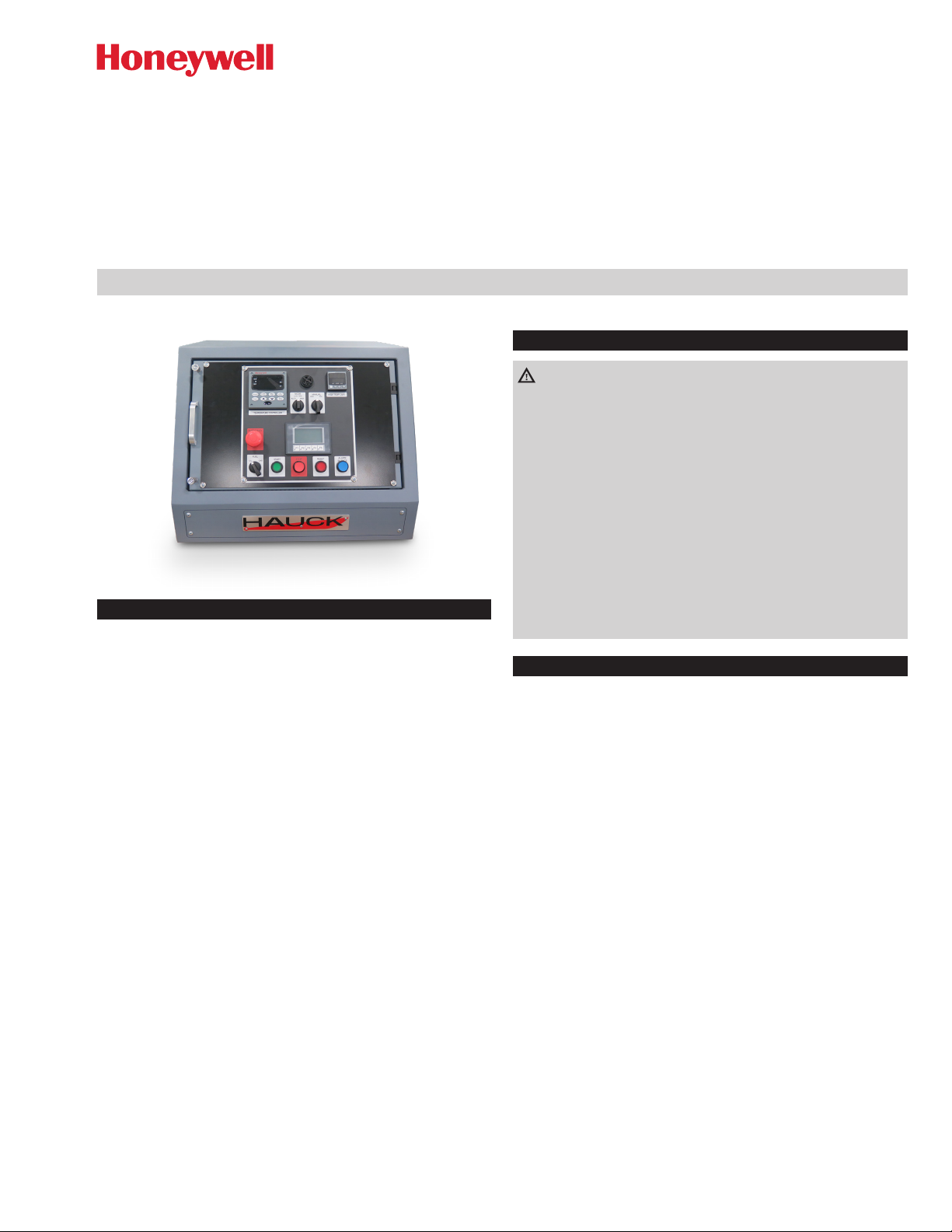
Burner Control System
BCS 3600
CONTENTS
Safety ........................................1
General Information
Receiving and Inspection
Installation
Adjustment
.....................................2
....................................2
Final Checkout
Panel Operation
Assistance in the event of malfunction
Human Machine Interface (HMI) Screens
Control motor slidewire calibration
UDC3200 Series Controller
Temperature controller configuration record sheet
High Temperature Limit
Exhaust Fan Flow Limit Switch Installation
Stack Thermocouple Installation
Material thermocouple installation
Recommended spare parts
Converting units
..............................1
.........................2
.................................3
................................3
................4
..............4
...................5
........................6
.......7
...........................8
.............9
...................10
..................11
.......................12
...............................12
OPERATING INSTRUCTIONS
Edition 11.19· ·
SAFETY
32-00248
WARNING
– This equipment is potentially dangerous with the possibility of
serious personal injury and property damage. Hauck Manufacturing Company recommends the use of flame supervisory
equipment and fuel safety shutoff valves. Furthermore, Hauck
urges rigid adherence to National Fire Protection Association
(NFPA) standards and insurance underwriter’s requirements.
Operation and regular preventative maintenance of this
equipment should be performed only by properly trained and
qualified personnel. Annual review and upgrading of safety
equipment is recommended.
– These instructions are intended for use only by experienced,
qualified combustion start-up personnel.
– Adjustment of this equipment and its components, by
unqualified personnel, can result in fire, explosion, severe
personal injury, or even death.
GENERAL INFORMATION
The Hauck Burner Control System (BCS) provides burner management and temperature control of a single pilot ignited burner firing
on gas, oil or liquid propane (LP). The spark ignited, gas fired pilot is
interrupted after the main burner flame has been established. Flame
supervision is provided by a Honeywell RM7890A1056 flame relay
combined with a R7849A1023 amplifier module and one or two
C7027A1049 UV scanners.
A Programmable Logic Controller (PLC) supervises burner operation
and is coupled to a Human Machine Interface (HMI) to provide the
operator with system status and fault annunciation.
A Honeywell UDC3200 series microprocessor based instrument is
provided for temperature control. The controller is electronically linked
to the burner control motor to automatically adjust the burner firing
rate and maintain process temperature near the controller’s setpoint.
The Temperature Controller’s thermocouple senses the temperature
of the material or exhaust gases as it exits the dryer, depending on
where it’s positioned. The controller generates a position proportional
output based on the difference between the setpoint and the process
temperature input.
The control MODE selector switch enables the operator to assign
control of the burner. The center, LOW FIRE, position of this switch is
used to hold the burner at low fire. The right, MAN (manual) position
enables the operator to increase (INC) or decrease (DEC) the burner
position via the MANUAL switch. The left, AUTO position uses the
Temperature Controller to operate the burner.
GB – www.docuthek.com
Page 2

The limit contact of the High Temp Limit instrument is used to shut
1
2
3
down the burner if the preset high temperature limit is exceeded.
An alarm contact is also used to alert the Operator when the stack
temperature nears the limit setting. Refer to HIGH TEMPERATURE
LIMIT for entering the desired alarm setpoints.
High temperature limits will not prevent baghouse fires. They will,
when properly installed and adjusted shut off the burner when the
limit’s temperature setpoint is exceeded. Outside factors such as
chemicals, bag contamination or other ignition sources are beyond
the control of the burner management system.
CAUTION
– The HIGH TEMP LIMIT setpoint is factory set at 400°F
(204°C). If the system is equipped with a fabric dust collector
(baghouse), consult the manufacturer for recommended
baghouse temperature limitations.
Part designations
1 UDC3200 Temperature Controller
2 High Temperature Limit
3 Human Machine Interface (HMI) Screens
RECEIVING AND INSPECTION
Upon receipt, check each item on the bill of lading and/or invoice to
determine that all equipment has been received. Examine all parts to
determine if there has been any damage in shipment. If equipment is
to be stored prior to installation, provide a dry storage area.
INSTALLATION
➔
For optimum use of the BCS panel, it is suggested that the drawings provided by Hauck be referred to for limit switch and valve
installation and wiring. In the event that a recommended switch or
valve is not used, it may be necessary to connect jumper wire(s)
between appropriate terminals in the control panel or burner
junction box. Such determination remains the responsibility of the
Customer, based upon his application, accepted safe installation
and operating procedures, and any applicable insurance guidelines
or governmental regulations.
➔
Locate the tabletop panel on a firm support in an area that is
protected from the weather and free from vibration. The drop-in
version is designed to install in an existing enclosure. Reference
the panel assembly drawings for mounting dimensions and required cutouts.
WARNING
– A ground wire is also required between the burner junction
box and the control panel terminal strip.
3
Determine the burner control motor type and install one of the
following jumpers:
a. From fuse 5 to Ground for a sinking type motor, Barber-Cole-
man EA57 medium torque.
b. From fuse 5 to 7A for a sourcing type motor, Barber-Coleman
EA71 or EA73 high torque.
➔ If the burner control motor needs to be driven open until purge
time is completed the control needs to be configured. See page
2 (Adjustment) for instructions.
4
Wire the fuel valves, valve position limit switches and fuel pressure
limit switches as shown on the external component wiring diagram.
5
Install the exhaust fan flow limit switch in the dryer exhaust duct
as shown in page 9 (Exhaust Fan Flow Limit Switch Installation) . Wire the normally open contact of the exhaust flow limit to
the appropriate terminals in either the burner junction box or the
BCS control panel.
6
Install a limit switch on the exhaust damper set to close when the
damper is greater than 50% open.
7
Install the stack temperature thermocouple in the dryer exhaust
duct to sense exhaust gas temperature. See page 10 (Stack
Thermocouple Installation) for installation instructions.
8
Install a Hauck Rapid Response material temperature thermocouple in the material discharge chute to sense the temperature
of the material leaving the dryer. See page 11 (Material thermocouple installation) for recommended installation.
9
Connect the thermocouples to the appropriate terminals in the
BCS control panel using thermocouple cable of the same type
as the Material and Stack thermocouples.
10
Install the pilot (if applicable) and main flame scanner(s) on the
burner and wire them to the appropriate terminals in the burner
junction box. Reference burner instructions for scanner installation
details.
11
Refer to the external component wiring diagram for interconnection between the burner junction box and the BCS panel terminal
strips.
ADJUSTMENT
1
Set the purge timer for the required purge time and whether the
control motor needs to be open during the purge cycle.
a
With the control power ON push the F4 (SETUP) button on the
HMI.
WARNING
– Operating specifications of 32 to 130°F (0 to 54°C), 30 to
95% relative humidity (non-condensing) should be considered
in selecting a suitable location for the control panel.
1
Provide 120Vac single phase grounded neutral power to the
burner control panel. It is recommended that the customer provide
a master disconnect switch to interrupt power service to the
panel. Maintain polarity as indicated on the drawings provided
when connecting the main power source to the panel.
2
Install a heavy gauge (No. 12 AWG minimum) ground wire between
the panel ground connector and "Earth" ground.
b
Push the SERVICE button on the HMI screen.
2
BCS 3600 · Edition 11.19 · EN
Page 3

c
Enter the service password using the keypad on the HMI.
WARNING
– Before igniting the burner, the dryer must be purged to remove
possible accumulation of combustible gases. A minimum of
four complete air changes must be supplied. Multiply the total
system volume (dryer, baghouse and exhaust ducts) in cubic
feet by four. Divide this value by the low fire air flow in cubic
feet per minute. The result will be the required purge time in
minutes
2
Perform the fuel motor calibration procedure described in page
5 (Control motor slidewire calibration).
➔ Recalibrate annually or whenever a control motor is serviced or
replaced.
3
Verify that all low fire limit switch contacts are closed when the
burner is at 0% and open when the burner leaves low fire. Reference the burner operating instructions for switch adjustment.
4
Verify that all purge permissive contacts are closed after the burner control motor drives open for purge (Sealed-in burners only).
FINAL CHECKOUT
1
Ensure sure that all equipment and components have been installed in accordance with the manufacturer's instructions.
2
Verify all wiring and tighten connections.
3
Confirm all linkage adjustments and insure that control arms and
linkage rods are tight.
4
Clean all traps and filters.
5
Check all fuel and air supply lines for leaks.
6
Verify all pressure settings.
d
Enter the amount of time needed to complete the purge cycle,
in seconds, into the purge timer window by selecting the PURGE
TIMER field and entering the time using the keypad on the HMI.
e
If the control motor needs to be open during the purge cycle turn
on the HIGH FIRE PURGE by touch the switch symbol.
f
Push the MAIN soft key to exit the SERVICE screen.
BCS 3600 · Edition 11.19 · EN
PANEL OPERATION
1
Open applicable manual shutoff valves to supply air and fuel to
the system.
2
Twist to release the EMERGENCY STOP button and verify that
the FUEL selector switch is in the desired position.
a
The Temperature Controller, High Temperature Limit and flame
relay will perform their self-test procedures.
b
The burner control motor will drive to its low fire position.
c
The RESET indicator will come on.
d
A “BURNER STOPPED” message will appear
3
Start the combustion air and exhaust fans and all other equipment
required for plant operation. After all safety limits have closed, a
“PRESS RESET TO START PURGE” message will appear.
4
Place the control MODE selector in the desired position and
verify setpoints of both the Temperature Controller and High Temperature Limit(s).
5
Momentarily press the RESET button to initiate the system purge
sequence.
a
Run Relay, CR102, will be energized.
b
The RESET indicator will go out.
c
If HIGH FIRE PURGE was setup in the SERVICE screen the burner control motor will drive open to prepare for system purge and
a “WAITING FOR PURGE LIMITS” message may appear (Sealedin burners only).
6
Provided that all purge permissive contacts are closed:
a
The Purge Timer will begin its timed delay, and a “PURGING …
SECONDS” message will appear.
7
After the purge delay, has been completed:
a
The PURGE COMPLETE relay, CR228, will be energized.
b
The burner control motor will drive closed to prepare for pilot
ignition (Sealed-in burners only).
c
A “WAITING FOR LOW FIRE LIMITS” message may appear.
8
When the motor has reached its low fire start position and the
burner low fire limit switches have closed:
a
“READY to START” will be displayed.
b
The START pushbutton will flash indicating that the burner is ready
to start.
9
Momentarily press the START pushbutton to begin the burner
ignition sequence
3
Page 4
a
Start Relay, CR320, will be energized.
b
The RM7890A flame relay will be energized and perform its safe
start check.
c
“IGNITING PILOT” will be displayed and the ignition transformer
and pilot solenoid valves will be energized.
10
If a satisfactory pilot flame is detected by the UV scanner:
a
Flame signal strength will be displayed on the HMI
b
A “PILOT ON” message will appear.
c
The ignition transformer will be de-energized.
d
Power will be supplied to the main fuel valves.
e
“MAIN VALVES ON” followed by “MAIN FLAME TRIAL” will be
displayed as the flame relay performs a 10 second main flame
trial for ignition.
11
After the ignition trial, has completed, the pilot solenoids will be
de-energized and the pilot will go out.
12
When a 10 second internal timer has been completed:
a
The pilot scanner will be de-energized, (If applicable).
b
The burner control motor will be released from low fire, and respond to the motor positioning outputs of the temperature controller.
13
Start material flow to the dryer. Use the ▲ and ▼ keys of the
Temperature Controller to manually control the burner firing rate,
or press the MANUAL/AUTO key on the controller to begin automatic temperature control.
➔ The center, LOW FIRE, position of the MODE switch will return
the burner to its low fire position.
➔
In the event of a Temperature Controller failure, the MAN. (MANUAL) position of the control MODE selector will enable the Operator
to increase (INC) or decrease (DEC) the burner via the MANUAL
INC/DEC switch.
14
To terminate burner operation, press the STOP pushbutton.
a
Run Relay, CR102, will be de-energized and the RESET indicator
will come on.
b
Purge Complete relay, CR228, and Start Relay, CR320, will be
de-energized and a “BURNER STOPPED” message will appear.
c
The Honeywell RM7890 flame relay will be de-energized.
d
All fuel valves will be de-energized.
e
The burner control motor will drive closed.
ASSISTANCE IN THE EVENT OF MALFUNCTION
?
No power to instruments or indicators.
• Check for 120Vac between L1 and L2. Reset circuit breaker.
?
“WAITING FOR PURGE LIMITS”
• Check purge limits series: 120Vac on terminals 19, 24C,
24B, 24A and 24.
?
“WAITING FOR LOW FIRE LIMITS”
• Check low fire series: 120Vac on terminals 19, 21B, 21A and
21.
?
"IGNITION FAILURE RESET REQUIRED”
• Verify operation of pilot solenoids and ignition transformer.
Check pilot adjustment and fuel supply.
• Check for 120Vac on terminals 8 and 9.
• Replace flame relay.
?
FLAME RELAY FAULT RESET REQUIRED
• Verify pilot and main burner setup.
• Clean UV scanner lens and verify operation.
?
“EXHAUST FAN FAULT”
• Monitor module 1 input 2. Check exhaust flow switch (terminal 12) and exhaust fan interlock (terminal 13)
?
“COMBUSTION AIR FAULT”
• Monitor module 1 input 3. Check combustion air interlock
(terminal 14) and air pressure switch (terminal 16)
?
“LOW GAS PRESSURE”
• Monitor module 1 input 4. Verify that the manual gas valve is
open and that the low gas pressure switch is made (120Vac
on terminal16A)
?
“HIGH GAS PRESSURE”
• Monitor module 1 input 7 and the high gas pressure switch is
made (120Vac on terminal18)
?
“OIL PRESSURE FAULT”
• Monitor module 1 input 5. Verify that the manual valve is
open and that the low and high pressure switches are made
(120Vac on terminal17A)
?
“ATOMIZING AIR FAULT”
• Monitor module 1 input 6. Verify that compressed air is available and that the supply pressure switch is made (120Vac on
terminal17C)
?
“OIL TEMPERATURE FAULT”
• Monitor module 1 input 7. For heavy oil systems, verify that
oil heater is operating and that both the low and high oil
temperature switches are made (120Vac on terminal18)
?
“COMPRESSED AIR FAULT”
• Monitor module 2 input 3. For oil firing with compressed air
atomization, the compressed air pressure switch must close
within 5 seconds after the compressed air solenoid is energized (120Vac on terminal 30A)
?
“HIGH LIMIT FAULT”
• Monitor module 2 input 2. (120Vac on terminal 26) Observe
the display and OUT indicator of the High Temp Limit instrument. “OPEN” indicates an open TC or broken wire. The
instrument must be manually reset by pressing the RESET
key.
?
“STACK TEMP NEAR LIMIT”
• Warns the Operator that the High Limit instrument is nearing
the High Limit setpoint (factory set at 380 F). Manually decrease the burner firing rate or increase material feed rate to
avoid burner shutdown.
?
PURGE TIMER NOT SET
• Warns the operator that the internal purge timer has not
been set in the PLC.
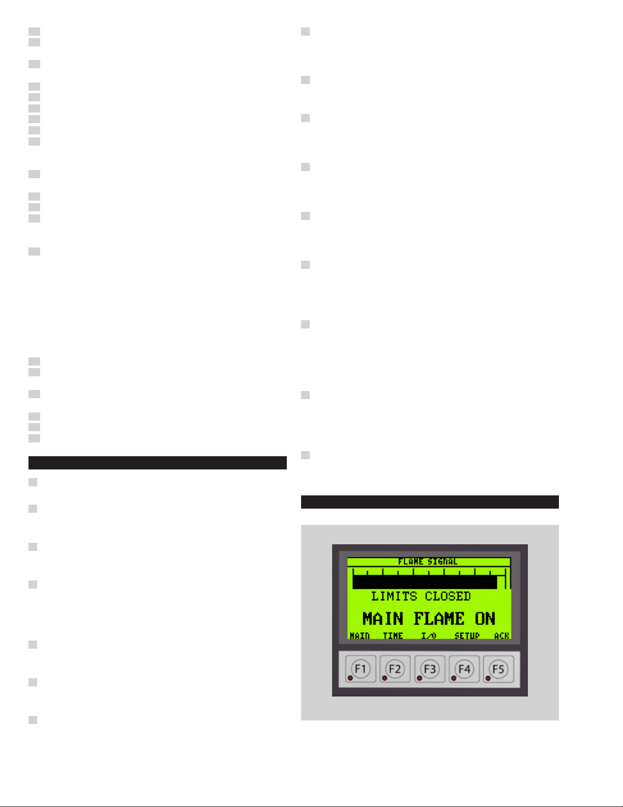
HUMAN MACHINE INTERFACE (HMI) SCREENS
Main
F1 Displays limits and system status along with flame signal strength.
BCS 3600 · Edition 11.19 · EN
4
Page 5

Time
ACK
F2 Displays resettable and accumulated firing time.
Input/Output
F3 Displays input and output status of the CPU module. Touch the
MODULE 1 and MODULE 2 buttons to display their input status
Setup
F5 key mimics the function of the alarm silence button. It also displays the alarm status message along with related troubleshooting
information.
CONTROL MOTOR SLIDEWIRE CALIBRATION
➔
The burner control motor incorporates a position feedback slidewire. A signal from the Temperature Controller is connected to
the slidewire in order to generate position feedback signal for
the control panel.
➔
The following calibration procedure must be performed before
operating the burner for the first time
➔
RECALIBRATE ANNUALLY OR WHENEVER A CONTROL
MOTOR, SLIDEWIRE OR TEMPERATURE CONTROLLER
IS SERVICED OR REPLACED.
1
Place the MODE selector in the AUTO position.
2
Press the F4 key to enter the SETUP screen.
F4 Enables contrast adjustment, Backlight color selection and Screen
Saver delay time.
Note: 0 = Screen Saver Disabled
BCS 3600 · Edition 11.19 · EN
Setup
3
The press the SERVICE soft key on the HMI and enter the password using the keypad screen to get to the SERVICE screen.
5
Page 6

Keypad
3200
SP 3200
DI
8
Wait for the zero value to stop changing and confirm that the
motor is in its low fire position then press [FUNCTION] again to
advance to SPAN VAL. The control motor will drive open and the
upper display value should increase. If it is necessary to reverse
control motor operation, interchange 2 and 3 and 7 and 8 on the
control motor terminal strip.
9
After the feedback value, has stopped increasing, confirm that
the motor has reached its high fire position then press [FUNCTION]
followed by [LOWER DISPLAY] to complete the calibration sequence.
10
Once the motor calibration is completed turn off the calibration
mode by selecting the MTR_CA soft key again.
UDC3200 SERIES CONTROLLER
➔ The Honeywell UDC3200 series controller has been configured
at the factory with parameters which generally produce accurate
temperature control.
➔ Before making any field adjustments, other then as noted in this
instruction sheet, please contact the Hauck service department.
Operator Interface
➔
This section describes the function of the various displays and keys
➔ Examples are given for changing the controller setpoint and op-
erating the burner in MANUAL.
➔
Detailed information is given in the vendor literature supplied with
the control panel.
Service
Motor calibration
4
5
6
7
Select the MTR_CA soft key on the HMI, this will enable the
burner control motor to be driven by the Honeywell Temperature
Controller without having to fire the burner.
Enter the calibration mode on the Temperature Controller by
pressing the [SETUP] key until the display reads CALIB POSITION.
Press the [FUNCTION] key to display DISABLE POS PROP then
press the ▲ key to change the upper display DO AUTO.
Press [FUNCTION] to begin motor calibration. The lower display
will read ZERO VAL while the upper display will show the slidewire
feedback value.
Head 1 Head 2
Upper display with 4 larger
digits shows Process Variabble
value (normal operation) and
special annunciator features.
During Configuration, the
upper display provides
guidance for the operator
through prompts (7 -
characters)
During normal operation, the
lower display shows key-
selected operation parameters
such as Output, Setpoints,
Inputs, Deviation, active
Tuniung Parameter Set, Timer
Status, or minutes remaining in
a setpoint ramp (4 digits).
During configuration, the lower
display provides guidance for
the operator through prompts.
ALM
6
Indicated alarm 1 and/or alarm
2 conditions exists.
Indicates digital input 1 and/or
2 on.
BCS 3600 · Edition 11.19 · EN
Page 7

Head 1 Head 2
OUT
MAN
A
SP
Indicates control relay 1 and/or
ForC
or
Keys and functions
Changing the setpoints
1
Press the [LOWER DISPLAY] key until SP and the current setpoint
appears in the lower display.
2
Press and hold the ▲ key to increase the set point value. To make
changes more quickly, press the ▼ key while holding ▲ key. This
will shift the changing digit one place to the left.
3
To decrease the set point value, reverse the above procedure.
Adjusting the burner firing rate in the manual mode
1
Press the [AUTO/MANUAL] key to place the Controller in the
Manual Mode. The MAN indicator will come on and the lower
display will automatically change to show % OUT.
2
Press and hold the ▲ key to increase % Output value. To make
changes more quickly press the ▼ key while holding ▲ key. This
will shift the changing digit one place to the left.
3
To decrease the % Output value, reverse the above procedure.
Indicated either degrees
Fahrenheit or Centigrade.
Indicates either Manuel or Auto
Indicates local setpoints #1.
Also, a bar is lighted when the
setpoint being used is shown
Selects functions within each
configuration groups.
Returns controller to normal
display from Set Up mode.
Toggles various operating
parameters for display.
Increases setpoints or output
configuration values or
configuration mode groups.
Selects Manual or Auto mode.
Hold key down to cycle
through configured setpoints.
Enables Run/Hold of the SP
ramp or program plus timer
Decreases setpoint or output
configuration values or
configuration mode groups.
NEMA 4x and IP66 screw
attachment (each corner).
2 on.
mode.
on the lower display.
configuration group
Scrolls through the
value. Increases the
changes functions in
Infrared tranceiver
start.
value. Decreases the
changes functions in
TEMPERATURE CONTROLLER CONFIGURATION
RECORD SHEET
SET UP
GROUP
TUNING
SP RAMP
ACCUTUNE
ALGORITHM
OUT ALG
INPUT 1
INPUT 2 IN 2 TYPE SLIDEW
CONTROL
CONTROL
cont.
COM
ALARMS
DISPLAY
LOWER
DISPLAY
(FUNNCTION)
PROP BD
RATE MIN
RESET RPM
SECURITY
LOCKOUT
AUTO MAN
RUN HOLD
SP SEL
SP RAMP
SP RATE
FUZZY
ACCUTUNE
CONT ALG
TIMER
IN ALG1
OUT ALG
MOTOR TI
IN 1 TYPE
IN 1 HIGH
IN 1 LOW
RATIO 1
BIAS IN 1
FILTER 1
BURNOUT 1
PV SOURCE
PID SETS
LSP'S
RSP SRC
SP TRACK
PWR MODE
SP HI LIMIT
SP LO LIMIT
ACTION
OUT RATE
OUT HI LIM
OUT LO LIM
I HI LIM
I LO LIM
DROPOFF
DEADBAND
FAILSAFE
FAILMODE
MAN OUT
AUTO OUT
PB OR GAIN
MIN OR RPM
COM ADDR
COMSTATE
IRENABLE
BAUD
TX DELAY
A1S1 TYPE
A1S2 TYPE
A2S1 TYPE
A2S2 TYPE
ALARM HYST
BLOCK
DIAGNOST
A1S1 VALUE
A2S1 VALUE
A2S2 VALUE
DECIMAL
TEMPUNIT
PWR FREQ
LANGUAGE
FACTORY
CONFIGURATION
15.00
0.00
1.00
0
NONE
ENABLE
DISABLE
ENABLE
DISABLE
DISABLE
DISABLE
DISABLE
PID A
DISABLE
NONE
POSITN
40
J TC L
550.0 F
20.00 F
1.000
0.0
1
UP
INPUT 1
1 ONLY
1 ONLY
NONE
NONE
MANUAL
550.0 F
20.00 F
REVERSE
DISABLE
100.0
0.0
100.0
0.0
0.0
2.0
0.0
NO LATCH
0.0
0.0
PB PCT
RPM
3
DISBALE
ENABLE
19200
1
NONE
NONE
NONE
NONE
0.1
DISABLE
DISABLE
Not Applicable
Not Applicable
Not Applicable
NONE
DEG F
60 HZ
ENGLISH
FINAL
SETTING
BCS 3600 · Edition 11.19 · EN
7
Page 8

HIGH TEMPERATURE LIMIT
The high temperature limit has been configured at the factory and
should not require any adjustments. The procedure for changing the
limit or alarm setpoint and a configuration record are given below.
Detailed information is given in the vendor literature supplied with
the control panel.
Changing the limit or alarm setpoint
1
Hold the SETUP key and press the ▲ key. The lower display will
show SLCT and the upper display will read OPTR.
2
Release the SETUP key and press the ▲ key until the upper
display reads SETP then press SETUP again to display the current
limit setpoint.
3
Use the ▲ or ▼ keys to change the setpoint.
4
Press SETUP to advance to PhA1 and again use the ▲ or ▼ keys
to change the alarm setpoint if desired.
5
Hold SETUP and press the ▲ key then release the SETUP key
and press the ▲ key until the upper display again reads OPTR;
then press SETUP to return to the operating (normal) display.
CONFIGURATION RECORD SHEET
➔ SLCT = CONF
➔ ULOC = 20
Lower Display
(Function)
INPT J.F
RUL 999.9
RLL -199.9
OFFS 0.0
CTRL HI
SPUL 999.9
SPLL -199.9
ALA1 P_HI
PHA1 380.0
AHY1 0.1
ALA2 PL_O
PLA2 -199.9
AHY2 0.1
USE2 A1_d
USE3 A2_d
DISP ENAB
CLOC 20
AHY2 0.1
AHY2 0.1
1
After completing Configuration, simultaneously press the ▲ and
SETUP keys. ConF will appear in the Upper Display.
2
Press the ▲ arrow key until the Upper Display reads SEtP then
press SETUP. ULoc will appear in the Lower Display.
3
Press the ▲ arrow until Upper Display reads 10.
4
Press SETUP to enter the set point mode.
Factory
Configuration
Final
Setting
5
Set the limit set point at 400 F and PhA1 at 380 F. All other settings
remain at their factory defaults.
Lower Display
(Function)
SP 400.0
HYSt 0.1
FiLt 2
PhA1 380.0
AHY1 0.1
PLA2 -199.9
AHY2 0.1
SLoc 10
8
Factory
Configuration
Final
Setting
BCS 3600 · Edition 11.19 · EN
Page 9

EXHAUST FAN FLOW LIMIT SWITCH INSTALLATION
Mount the exhaust fan flow switch in the dryer exhaust duct as
shown below.
1
Cut a 2" hole in the duct where the pitot tube will be located.
2
For "blind" applications, mark two of the holes using one half of
the mounting flange.
3
Reach through the 2" hole to hold the nuts in place to mount the
plate half. Use silicone sealant as a gasket. Tighten the nuts and
bolts securely. Insert the pitot approximately 12" into the duct
and hold in place.
4
Using the second half of the flange, tighten the 1/4-20 bolts to
hold the pitot in place.
BAG HOUSE
AIR FLOW DIRECTION
WARNING
– Do not fasten both halves of the flange. One side is left
unbolted for removal and cleaning of Pitot tube.
5
For other applications, weld the four duct mounting nuts to the
inside of the ductwork using the flange as a pattern.
6
Use silicone caulk as a gasket
7
Remote mount the pressure switch to a vibration and heat free
location. Connect the plastic tubing from the pitot to the switch
connecting the upstream side of the pitot to the bottom of the
switch and the downstream side of the pitot to the top side of
the switch. Wire switch per schematic
UPSTREAM
DOWNSTREAM
DOWNSTREAM
12“
UPSTREAM
PRESSURE
CONNECTION
PRESSURE
CONNECTION
STACK
1 1/2 DIA.
HOLE
DUCT CUTDOWN DETAIL
FOR SWITCH
ASSEMBLY MOUNTING
(4) 7/16 DIA.
HOLES EQ. SPACED
ON A 3“ DIA BC.
45°
BCS 3600 · Edition 11.19 · EN
9
Page 10

STACK THERMOCOUPLE INSTALLATION
➔ Install a Hauck stack temperature thermocouple in the dryer ex-
haust duct to sense exhaust gas temperatures.
Exhaust duct (Located before dry
dust collector & exhaust fan).
When two thermocouples are used with bacghouse
installation locate before and after baghouse.
1 – 3/8“ Dia.
1“ Pipe coupling
center over 1 – 3/8 dia.
hole and weld.
Drawing showing placement of thermocouple in exhaust duct.
➔
Thermocouple cables must be separated from AC power and
control wiring to avoid interference and nuisance shutdowns.
Observe polarity when making thermocouple connections. Regardless of TC type, the red wire is always negative.
ow
fl
ir
A
1/2“ Conduit
connection
Dryer stack
thermocouple assy.
10
BCS 3600 · Edition 11.19 · EN
Page 11

MATERIAL THERMOCOUPLE INSTALLATION
Brass adapter
➔ Install a Hauck Rapid Response Material Temperature Thermo-
couple in the material discharge chute to sense the temperature
of the material leaving the dryer.
Access door
15°
1“ Pipe coupling
(intalled by customer)
DAM
bushing
Thermocouple
Set-screw
F
l
ow
Discharge
chute
15“ REF
Drawing showing the placement of the thermocouple and "dam"
in the dryer discharge chute.
➔
A small clearance (1" maximum) should be provided under the
thermocouple so material will not be trapped between the thermocouple and the chute. Trapped material will cause a heat loss
path and the thermocouple will give erroneous readings.
➔
The thermocouple should make good contact with the material but
not be subject to severe abrasion caused by high velocities. If the
material is moving so fast that it bounces and leaves air adjacent
to the thermocouple, the temperature it senses will be lower than
the material. It may be necessary to place a dam in the chute so
that the thermocouple is in a relatively slow moving area next to
the dam. The dam must only be wide enough and high enough
to create a localized area of build-up where the material loses
velocity BUT DOES NOT STOP FLOWING. The thermocouple
must not be located in a stagnant zone or erroneous temperature
readings will result. Because of the large number of variables
involved, it is impossible to set down any exact size or location
of the dam that will always work. Field experimentation will be
neces¬sary if good results are to be obtained. It is advisable to
tack weld the dam in place so that it can be easily modified if it
fails to perform satisfactorily.
➔
During normal operation, the thermocouple should be rotated
once a month to expose a different area of its surface to the
abrasive forces of the material. This procedure will increase the
effective life of the thermocouple. If excessive wear occurs, a
protective tube may be added to shield the shaft in the region of
the high velocity flow
➔
Thermocouple cables must be separated from AC power and
control wiring to avoid interference and nuisance shutdowns.
Observe polarity when making thermocouple connections. Regardless of TC type, the red wire is always negative.
➔ Wire the thermocouple to the proper terminals in the panel.
10“
REF
BCS 3600 · Edition 11.19 · EN
11
Page 12

RECOMMENDED SPARE PARTS
PART NO. QTY DESCRIPTION
HK302263 1 Flame Relay RM7890A1056
14553 1 Flame Amp R7849A1023
16281 2
Honeywell UV Scanner
C7027A-1049
PRJ101034364 1 Honeywell UDC3200
HK402731 1 High Temperature Limit
101044055 1 Click Analog CPU C0-12ARE-D
101044056 1
101044057 1
Click 8 point AC Input Module
C0-08TR
Click 8 point Relay Output
Module C0-08NA
101033971 1 Click Power Supply C0-01AC
10049313 2
HK55167 5
HK43868 1
Relay, DPDT, Phoenix Contact,
PLC-RSC-120UC/21-21
Fuse, 7A, ¼ x 1-1/4, Littlefuse
type 313007
Stack Thermocouple, Hauck
TC200A-J
CONVERTING UNITS
see www.adlatus.org
FOR MORE INFORMATION
The Honeywell Thermal Solutions family of products includes Honeywell
Combustion Safety, Eclipse, Exothermics, Hauck, Kromschröder and
Maxon. To learn more about our products, visit
www.ThermalSolutions.honeywell.com or contact your Honeywell Sales
Engineer.
Honeywell Process Solutions
Honeywell Thermal Solutions (HTS)
1250 West Sam Houston Parkway
South Houston, TX 77042
ThermalSolutions.honeywell
© 2019 Honeywell
12
BCS 3600 · Edition 11.19 · EN
We reserve the right to make technical modifications in the interests of progress.
 Loading...