

31-00096-02
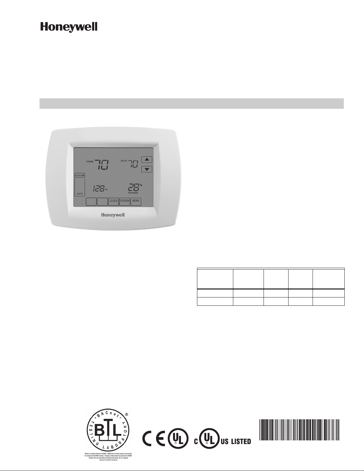
BACnet® Fixed Function Thermostat
FOR FAN COIL/HEAT PUMP/CONVENTIONAL SYSTEMS
SPECIFICATION DATA
FEATURES
• 19 pre-loaded applications for a quick, out-of-thebox solution.
• Optional integrated wireless receiver saves wiring
time and costs, provides more location options.
• Internal temperature and humidity sensors, 3
universal inputs, 6 relay outputs, 2 analog outputs.
• BACnet-compliant on MS/TP LAN at up to 76.8 Kbps
with an internal DDC logic loop of 100 msec.
• A configurable device that is capable of stand-alone
or integrated operation.
• Sleek sophisticated design with touch screen display
with dual setpoints.
APPLICATION
The BACnet Fixed Function (BACnet FF) thermostats are
configurable devices with 19 factory-loaded applications
for specific and common projects including fan coil, heat
pump and roof top equipment control.
The BACnet FF thermostats come in two models, the
standard TB3026B and the wireless enabled TB3026B-W.
Each model is a communicating, intelligent sensorcontroller combination with built-in temperature and
humidity sensors used to control the pre-loaded
applications. They provide a cost effective solution for
occupancy and crowd monitoring in hotel rooms,
conference rooms, schools, office buildings and more. The
large, easy-to-see display and easy-to-use interface
allows for the complexity of direct digital control (DDC) in
a user friendly package.
The BACnet FF thermostats communicate over an MS/TP
LAN so each device operates as a fully functioning BACnet
controller while easily integrating with the building
automation system. These devices are configured using
the Niagara Framework® software where a configuration
wizard will enable an intuitive setup.
DESCRIPTION
The BACnet FF thermostats are available in two models, as
described in Table 1.
Table 1. Thermostat Configurations.
Thermostat
Model
TB3026B 3 2 6 NO
TB3026B-W 3 2 6 YES
Both thermostat models are configurable and come with
19 factory-loaded applications. The TB3026B-W includes
an integral wireless receiver providing compatibility with
wireless occupancy sensors.
UI
(Universal
Input)
Equipment Control Options
• 2-Pipe Fan Coil, 4-Pipe Fan Coil, Water/Air Source Heat
Pump, Roof Top Unit
• On/Off, Three Speed or VFD Controlled Fan
• Floating, Two-Position or Analog Cooling/Heating
Valve Control
• On/Off Compressor and Heating Stages
• Floating or Analog Economizer Control
• Space, Outdoor or Supply Air Remote Sensors
AO
(Analog
Output)
DO
(Relay
Output)
Integrated
Wireless
Receiver

FOR FAN COIL/HEAT PUMP/CONVENTIONAL SYSTEMS
WARNING
SPECIFICATIONS
Power
24VAC power from a UL Listed Class-2 24VAC transformer
(not provided). The BACnet FF uses a half-wave rectifier
to convert the AC power supply to onboard power. This
enables multiple devices with half-wave power supplies
to be powered from a single, grounded transformer.
Half wave devices and full wave devices must not
use the same AC transformer.
You must maintain wiring polarity. Failure to do so
can result in equipment damage.
If the HVAC equipment has an internal circuit board
that is powered by the same transformer that will
power the BACnet FF, verify that it is NOT full wave.
Min. Load = 17VA (all BOs OFF).
Max. Load = 89VA (all BOs ON).
If BO power jumper is not removed, then all BOs are pow-
ered from the controller’s transformer.
Minimum load includes controller and analog outputs at
full load (20mA into 500 Ohms).
All BOs are N.O. (Normally Open) contacts with a maximum
switch rating of 24VAC @ 0.5A (12VA).
Maximum load assumes all 6 relay output loads are pow-
ered from the controller transformer and connected
loads are the maximum allowed (24VAC @ 0.5A). Actual
power requirements depend on connected loads.
Wireless Receiver (TB3026B-W only)
433.92 Mhz; range is 50 feet.
Inputs
3 universal inputs with 12-bit accuracy, providing con-
trolled voltage, current and resistive modes. Requires a
10k type 2 thermistor when using remote sensors.
Internal Sensors
1 internal temperature sensor, 0–120 deg. F (-17.8–48.9
deg. C); 1 internal humidity, 5–95% RH, non-condensing.
Relay Outputs
6 relay outputs; normally open contacts with a maximum
switch rating of 24VAC @ 0.5A (12VA). BO-0, BO-2 and
BO-5 are powered from the controller transformer. BO1, BO-3 and BO-4 are powered from control transformer
through removable jumper, allowing these BOs to be
powered from a separate power source.
Universal Analog Outputs
2 outputs with 12-bit resolution. Each auto-detects for 0–
10VDC or 4–20mA. 4–20mA outputs are sourced by the
BACnet FF. Connected loads must return to the
BACnet FF ground. The BACnet FF automatically
switches from 0–10V mode to 4–20mA current mode
when it detects a load value of less than 500 Ohms.
Processor & Memory
Powerful 32-bit processor with extensive flash memory
and RAM resources. Flash memory provides nonvolatile
program and data storage, and allows for encrypted
updates to the program for future product enhancements.
Environmental
Residential, commercial and light-industrial environments.
0–120 deg. F (-17–49 deg. C). 0–95% RH, non-condensing.
Communications
BACnet MS/TP LAN up to 76.8Kbps.
Ratings
Listed Temperature Sensing Controls for US and Canada
(XACX, XACX7 under UL 60730-2-9, CSA C22.2
No. 60730-2-9, File E481079.
EMC Directive (European CE Mark) EN 60950
(TB30326B-W model only).
This equipment has been tested and found to comply with
the limits for a Class B digital device, pursuant to part 15 of
the FCC Rules. These limits are designed to provide
reasonable protection against harmful interference in a
residential installation. This equipment generates uses and
can radiate radio frequency energy and, if not installed and
used in accordance with the instructions, may cause
harmful interference to radio communications. However,
there is no guarantee that interference will not occur in a
particular installation. If this equipment does cause
harmful interference to radio or television reception, which
can be determined by turning the equipment off and on,
the user is encouraged to try to correct the interference by
one or more of the following measures:
— Reorient or relocate the receiving antenna.
— Increase the separation between the equipment and
receiver.
— Connect the equipment into an outlet on a circuit
different from that to which the receiver is connected.
This device complies with Part 15 of the FCC rules.
Operation is subject to the following two conditions: (1)
this device may not cause harmful interference, and (2)
this device must accept any interference received,
including interference that may cause undesired
operation.
This Class B digital apparatus complies with Canadian
ICES-003.
This device complies with Industry Canada license-exempt
RSS standard(s). Operation is subject to the following two
conditions: (1) this device may not cause interference, and
(2) this device must accept any interference, including
interference that may cause undesired operation of the
device.
Communications
Each device uses a BACnet MS/TP communications port.
The device’s data is presented to other devices over a
twisted-pair MS/TP network, which uses the EIA-485
signaling standard capable of the following baud rates: 9.6,
19.2, 38.4, or 76.8 kilobits per second (configured at global
controller). The BACnet FFs are master devices on the
31-00096—02 2

FOR FAN COIL/HEAT PUMP/CONVENTIONAL SYSTEMS
MS/TP network. Each BACnet FF device uses a highquality EIA-485 transceiver and exerts 1/4 unit load on the
MS/TP network.
Cabling should be selected that meets or exceeds the
BACnet Standard which specifies the following: an MS/TP
EIA-485 network shall use shielded, twisted-pair cable with
characteristic impedance between 100 and 130 ohms.
Distributed capacitance between conductors shall be less
than 100 pF per meter (30 pF per foot). Distributed
capacitance between conductors and shield shall be less
that 200 pF per meter (60 pF per foot). Foil or braided
shields are acceptable. The Honeywell tested and
recommended MS/TP cable is Honeywell Cable 3322 (18
AWG, 1-Pair, Shielded, Low Cap, Plenum cable),
alternatively Honeywell Cable 3251 (22 AWG, 1-Pair,
Shielded, Plenum cable) is available and meets the BACnet
Standard requirements (www.honeywellcable.com).
The BACnet MS/TP network is polarity sensitive. The
maximum BACnet MS/TP network Bus segment length is
4,000 ft. (1,219 m) using recommended wire. Repeaters
must be used when making runs longer than 4,000 ft.
(1,219 m). A maximum of three repeaters can be used
between any two devices.
MS/TP MAC Address
The MS/TP MAC address for each device must be set to a
unique value in the range of 0-127 on an MS/TP network
segment. The MAC address is set using the installer setup
menu through the device’s display. The factory default
MAC address is 0.
Device Instance Number
The Device Instance Number must be unique across the
entire BACnet system network because it is used to
uniquely identify the BACnet devices. It may be used to
conveniently identify the BACnet device from other devices
during installation. The Device Instance Number is set
using the installer setup menu through the device’s display
or over the BACnet network. The Device Instance Number
can be changed by the user, which may be necessary when
integrating with a third party or when attempting to replace
an existing device and it is desired to maintain the existing
Device Instance Number. The factory default Device
Instance Number is 0009999 and can range from
0-4194302.
NOTE: For complete instructions on how to set the
MS/TP MAC address or set the Device Instance
Number refer to the Installation Instructions, form
31-00093.
Termination Resistors
Matched terminating resistors wired across MS/TP+ and
MS/TP– are required at the last device on each end of the
MS/TP segment for signal integrity.
Optimum segment performance typically requires “tuning,”
a process by which the value of the terminating resistors is
selected based on the wave form of signals on the
segment. View wave forms using an industrial scope meter.
The goal is to have as square a wave form as possible with
an amplitude greater than 200 mV. Resistors affect the
wave form as follows:
• When the resistance value decreases, the amplitude of
the wave form decreases and becomes more square.
• When the resistance value increases, the amplitude of
the wave form increases and becomes less square.
Typically, precision resistors in the range 80-130 Ohms
(+1%) yield acceptable results. Ideally, the value of the
terminating resistors should match the rated characteristic
impedance of the installed cable. For example, if the
installed
MS/TP cable has a listed characteristic impedance of 100
Ohm, install 100 Ohm matched precision resistors.
Grounding MS/TP LAN Shield
Proper shield grounding of the MS/TP cabling can help
minimize the risk of communications problems and
damage to equipment because of transient voltage spikes
(for example, lightning strikes).
Follow these guidelines for grounding MS/TP cable
shields:
• Each MS/TP segment should have a single point of
shield ground, preferably as close to the middle of the
cabling run as possible.
• Do not ground the MS/TP shield using a BACnet FF
terminal.
• Never ground both ends of a shield; differences in
potential between the grounds may induce current on
the shield, causing interference.
• At termination connecting points, tie the shield through
with a wire nut.
• At ungrounded, exposed shield points (the end of a
segment), tape back the shield to the wire jacket or, for
optimum transient shunting, use 100 V gas discharge
tubes or 120 V MOVs between shield and ground.
Table 2. BACnet Interoperability Building Blocks (BIBBs)
Supported.*
DS-RP-A,B DM-DOB-B
DS-RPM-B DM-DCC-B
DS-WP-A,B DM-PT-A,B
DS-WPM-B DM-TS-B
SCHED-I-B DM-UTC-B
DM-DDB-A,B DM-RD-B
* Refer to the PICS (Protocol Implementation Conformance
Statement) for complete details, 31-00102.
Accessories
— 50037735-001 Wireless door/window sensor
— 50037736-001 Wireless passive infrared (PIR)
motion sensor
3 31-00096—02

FOR FAN COIL/HEAT PUMP/CONVENTIONAL SYSTEMS
Mounting
The thermostat consists of a front cover and back plate.
The device is wired on the back plate where the terminals
are located. Indicator arrows on the back plate will show
the proper orientation of the device. To prevent damage
during installation, align the pins on the front cover with
the terminal blocks for proper assembly.
NOTE: The thermostat must be mounted in a position
that allows clearance for wiring, servicing, and
removal.
NOTE: For complete mounting information, refer to the
Installation Instructions, form 31-00093.
Fig. 1. BACnet FF thermostat front cover,
dimensions in in. [mm].
Fig. 2. BACnet FF thermostat back plate,
dimensions in in. [mm].
N
IAGARA FRAMEWORK® and the Niagara framework logo are registered trademarks of Tridium, Inc.
BACnet
BTL
®
is a registered trademark of ASHRAE.
®
is a registered trademark of BACnet International.
By using this Honeywell literature, you agree that Honeywell will have no liability for any damages arising out of your use or
modification to, the literature. You will defend and indemnify Honeywell, its affiliates and subsidiaries, from and against any
liability, cost, or damages, including attorneys’ fees, arising out of, or resulting from, any modification to the literature by you.
Automation and Control Solutions
Honeywell International Inc.
1985 Douglas Drive North
Golden Valley, MN 55422
customer.honeywell.com
® U.S. Registered Trademark
© 2016 Honeywell International Inc.
31-00096—02 M.S. 07-16
Printed in United States
 Loading...