

BACnet® Fixed Function Thermostat
MERCURY NOTICE
CAUTION
FOR FAN COIL/HEAT PUMP/CONVENTIONAL SYSTEMS
INSTALLATION INSTRUCTIONS
APPLICATION
Honeywell’s BACnet® Fixed Function Thermostat, BACnet
FF, is a configurable device with 19 pre-loaded
applications. The thermostat is a communicating,
intelligent sensor-controller combination with built-in
temperature and humidity sensors used to control
systems such as roof top units, fan-coil units and heat
pumps. The thermostat communicates over an MS/TP
LAN so it operates as a fully-functioning BACnet
controller and easily integrates with the building
automation system. The two available models are
TB3026B and TB3026B-W, which includes a wireless
sensor option.
INSTALLATION
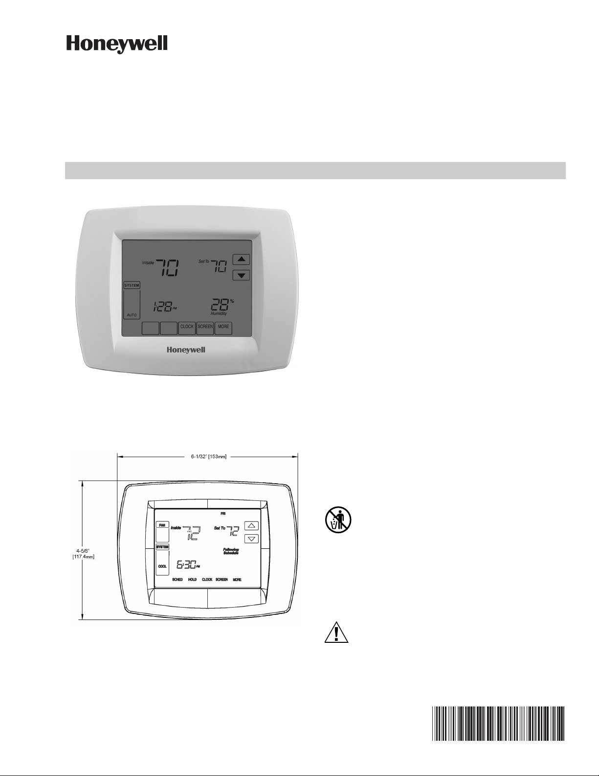
Dimensions
The Fixed Function Thermostat consists of a mounting
plate and a circuit board with a plastic cover.
Fig. 1. Fixed Function Thermostat dimensions.
When Installing this Product...
1. Read these instructions carefully. Failure to follow
them could damage the product or cause a
hazardous condition.
2. Check ratings given in instructions and on the
product to ensure the product is suitable for the
application.
3. Installer must be a trained, experienced service
technician.
4. After installation is complete, check out product
operation as provided in these instructions.
If this control is replacing a control that contains
mercury in a sealed tube, do not place your old
control in the trash. Dispose of properly.
Contact your local waste management authority
for instructions regarding recycling and the proper
disposal of an old control. If you have questions,
contact Honeywell Customer Care Center.
Electrical Shock or Equipment Damage Hazard.
Can shock individuals or short equipment
circuitry.
Disconnect power supply before installation.
31-00093-03
BACNET® FIXED FUNCTION THERMOSTAT
CAUTION
4 FEET
(1.2 METERS)
YES
NO
NO
NO
M36229
20
19
18
17
16
15
14
13
12
11
M36230
10
9
8
7
6
5
4
3
BO-5
BO-4
BO-3
BO-2
GND
AO-0
COM
AO-1
MS TP
+
MS TP
–
24VAC = HOT
RELAY
24VAC
BO-0
BO-1
GND = NEUTRAL
AI/BI-0
COM
AI/BI-1
COM
AI/BI-2
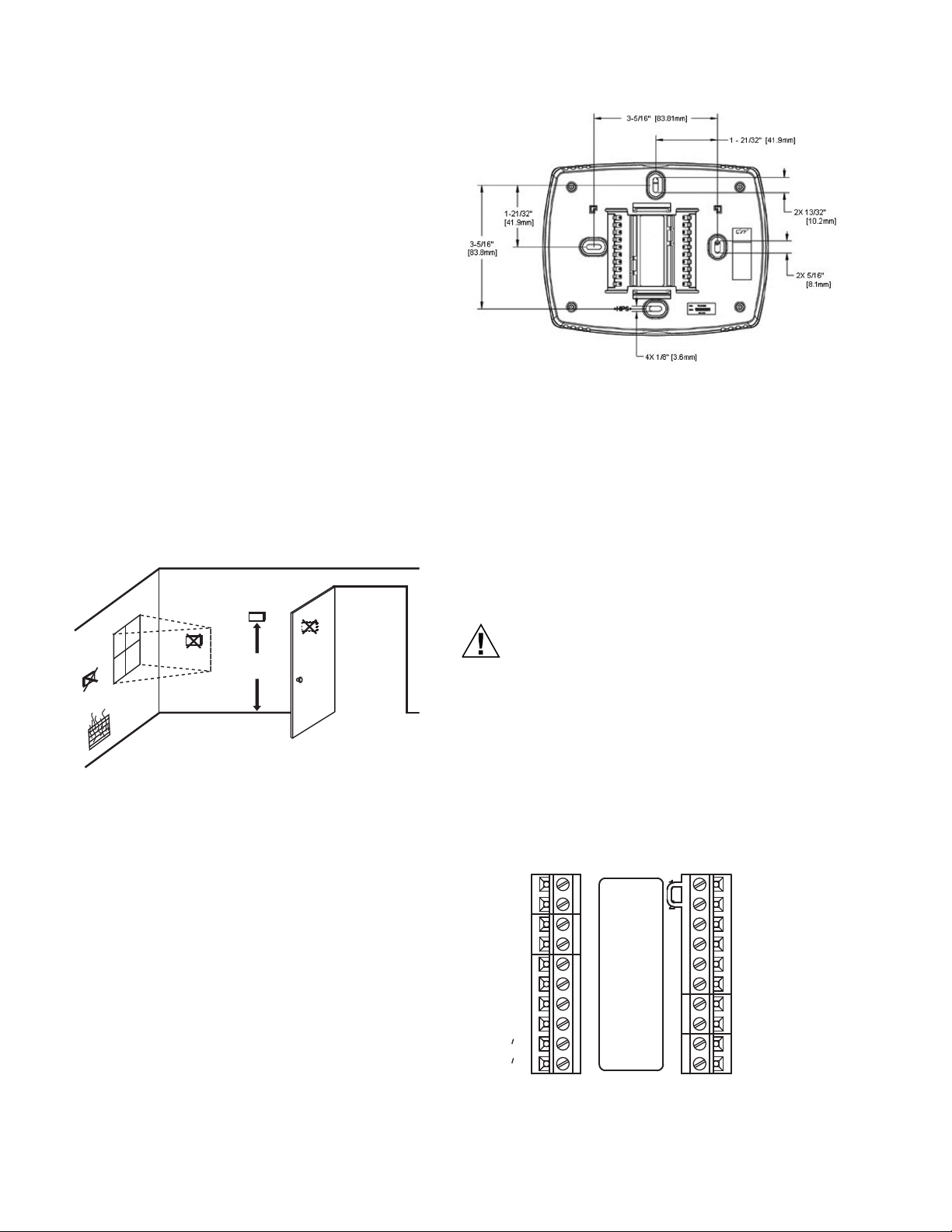
Location
Do not install the thermostat where it can be affected by:
— drafts or dead spots behind doors and in corners.
— hot or cold air from ducts.
— radiant heat from sun or appliances.
— concealed pipes and chimneys.
— unheated (uncooled) areas such as an outside wall
behind the thermostat.
IMPORTANT
To avoid electrical interference, which can cause
erratic performances, keep wiring runs as short as
possible and do not run thermostat wires adjacent
to the line voltage electrical distribution systems.
Use shielded cable. The cable shield must be
grounded only at the controlled equipment case.
WHEN USED TO SENSE ROOM TEMPERATURE
Install the thermostat about 4 ft. (1.2m) above the floor in
an area with good air circulation at average temperature.
(See Fig. 2.) Confirm mounting height meets Americans
with Disabilities Act requirements.
WHEN NOT USED TO SENSE ROOM TEMPERATURE
When using the remote-mounted temperature (and
humidity) sensor(s) to sense ambient conditions, install
the thermostat in an area that is accessible for setting and
adjusting the temperature and settings.
Fig. 3. Wallplate dimensions.
Wiring the Wallplate
IMPORTANT
All wiring must comply with local electrical codes
and ordinances.
NOTE: Maximum (and recommended) wire size is 18-
gauge. Do not use wire smaller than 22-gauge.
Follow equipment manufacturer wiring instructions when
available. A letter code is located near each terminal for
identification.
Power must not be connected while wiring.
Wiring a unit that is powered may result in
electrical shock and/or equipment damage.
Mounting Wallplate
The thermostat can be mounted horizontally on the wall or
on a 4 in. x 2 in. (101.6 mm x 50.8 mm) wiring box.
1.
2. Use a pencil to mark the mounting holes (see Fig. 3).
3.
4. Pull the wires through the wiring opening, and posi-
5. Insert the screws into the holes and tighten.
31-00093—03 2
Fig. 2. Typical location of thermostat
or remote-mounted sensor.
Position and level the wallplate (for appearance only).
Drill two pilot holes in the wall, on the marks. For drywall, drill 3/16-in. holes. For firmer material such as
plaster, drill 7/32-in. holes. Gently tap anchors (provided) into the pilot holes until flush with the wall.
tion the wallplate over the mounting holes.
1. Connect wires to the terminal blocks. See Fig. 4 for
terminal assignments and Table 1 for terminal
descriptions.
2. Securely tighten each screw.
3. Push excess wire back into the hole.
4. Plug the hole with non-flammable insulation to pre-
vent drafts from affecting the Fixed Function Thermostat.
5.
Check for loose or frayed wire that may cause a short.
Fig. 4. Fixed Function Thermostat terminal
assignments.
BACNET® FIXED FUNCTION THERMOSTAT
WARNING
Do not apply line voltage to source pins.
A jumper is pre-installed between pins 1 and 2. The
jumper supplies 24 VAC to BO-1, BO-3, and BO-4 relays. It
can be removed if those BOs are powered from an external
source. (Note: BO-0, BO-2, and BO-5 relays are powered
from terminal 1.)
See BACnet Fixed Function Thermostat System
Engineering Guide (31-00098) for typical wiring
examples.
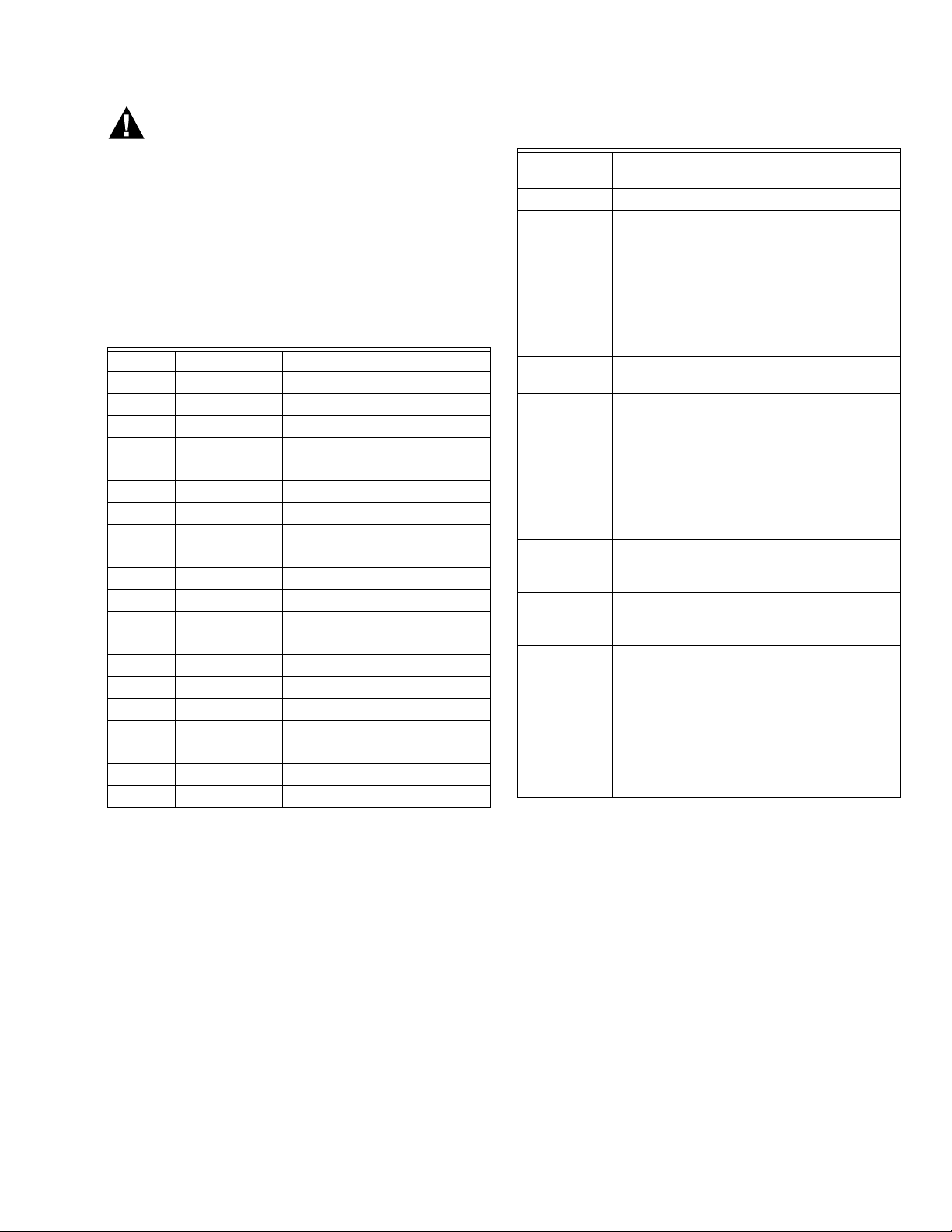
Table 1. Terminal Identification.
Terminal Label Connection
1 24VAC 24 VAC Power
2 RELAY 24VAC 24 VAC Power
3 BO0 Relay Output
4 BO1 Relay Output
5 GND Ground
6 AI0 Universal Input
7 COM Common
8 AI1 Universal Input
9 COM Common
10 AI2 Universal Input
11 MS/TP - BACnet ® Communications
12 MS/TP + BACnet ® Communications
13 AO1 Analog Output
14 COM Common
15 AO0 Analog Output
16 GND Ground
17 BO2 Relay Output
18 BO3 Relay Output
19 BO4 Relay Output
20 BO5 Relay Output
Table 2. MS/TP LAN Facts.
Tra nsm ission
speed
Layout Bus (daisy chain).
Cabling BACnet specifies the following. Shielded,
Segment
length
Maximum
devices
overall
Maximum
devices per
segment
Repeaters Required when making runs longer than
Ter min ating
resistors
Shield
grounding
9.6, 19.2, 38.4, 76.8Kbps (configured at
global controller).
twisted-pair cabling with characteristic
impedance between 100 and 130W.
Distributed capacitance between
conductors must be less than 30 pF/foot
(100 pF/m). Distributed capacitance
between conductor and shield must be
less than 60 pF/foot (200 pF/m). Foil or
braided shield acceptable.
4000 ft. (1071 m.) per segment using
recommended wire.
Depends on classification of devices as
master or slave. Maximum number of
master devices is 128. Maximum number
of slave devices or devices overall (mixed
master and slave) is 255. This includes
BACnet FFs, BACnet global controllers (all
are considered masters) and any other
devices, regardless of their relative unit
loads.
Depends on relative unit load of devices
(see “Terminating MS/TP LAN Cabling” on
page 3).
4000 ft. Three repeaters maximum
between any two devices.
Matched resistors required at each end of
segment bus wired across (+) and (–). Use
matched precision resistors rated |
1/4 W ±1% / 80 - 130 Ohms.
Ground shield drain wire at single point
earth (panel) ground, not BACnet FF
ground. Tape off shield drain wire at other
end. Tie shield drain wire through at each
BACnet FF.
MS/TP LAN Wiring
The BACnet FF communicates on the site-wide BACnet
system over a twisted-pair MS/TP LAN, which uses the
EIA–485 signaling standard. The BACnet FFs are master
devices on the MS/TP LAN.
Each BACnet FF employs a high-quality EIA–485
transceiver and exerts 1/4 unit load on the MS/TP LAN.
Terminating MS/TP LAN Cabling
MS/TP terminations are located on the lower left of the
BACnet FF wallplate.
Maintain polarity of the MS/TP wire run throughout the
MS/TP LAN.
Grounding the MS/TP LAN Shield
Proper shield grounding of the MS/TP cabling can help
minimize the risk of communications problems and
damage to equipment because of transient voltage spikes
(for example, lightning strikes).
Follow these guidelines for grounding MS/TP cable
shields:
• Each MS/TP segment should have a single point of
shield ground, preferably as close to the middle of the
cabling run as possible.
• Do not ground the MS/TP shield using a BACnet FF
terminal.
3 31-00093—03
BACNET® FIXED FUNCTION THERMOSTAT
CAUTION
• Never ground both ends of a shield; differences in
potential between the grounds may induce current on
the shield, causing interference.
• At termination connecting points, tie the shield through
with a wire nut.
• At ungrounded, exposed shield points (the end of a
segment), tape back the shield to the wire jacket or, for
optimum transient shunting, use 100V gas discharge
tubes or 120V MOVs between shield and ground.
Terminating Resistors
Matched terminating resistors wired across MS/TP+ and
MS/TP– are required at the last device on each end of the
MS/TP segment for signal integrity (Fig. 5).
Optimum segment performance typically requires
“tuning,” a process by which the value of the terminating
resistors is selected based on the wave form of signals on
the segment. View wave forms using an industrial scope
meter. The goal is to have as square a wave form as
possible with an amplitude greater than 200 mV. Resistors
affect the wave form as follows:
• When the resistance value decreases, the amplitude of
the wave form decreases and becomes more square.
• When the resistance value increases, the amplitude of
the wave form increases and becomes less square.
WALL
INSTALLATION
REMOVE DURING
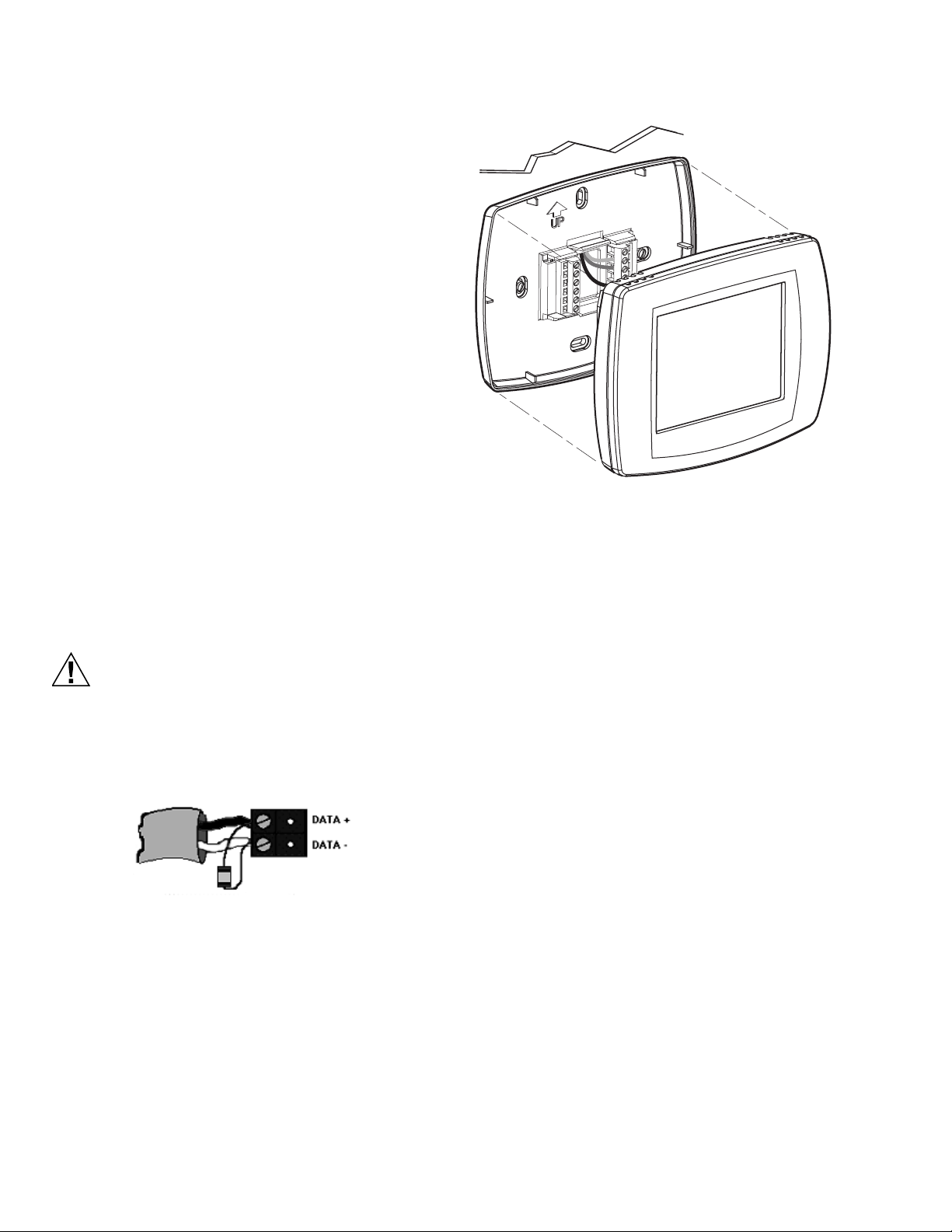
Fig. 6. Thermostat mounting.
M19919
Typically, precision resistors in the range 80-130 Ohms
(+1%) yield acceptable results. Ideally, the value of the
terminating resistors should match the rated
characteristic impedance of the installed cable. For
example, if the installed MS/TP cable has a listed
characteristic impedance of 100 Ohm, install 100 Ohm
matched precision resistors.
Do not mismatch terminating resistors.
Ensure that both resistors on a segment have the
same value.
NOTE: Typically, White is Data - and Black is Data +.
Fig. 5. Terminating resistor detail.
Mounting Thermostat to Wallplate
1. Align the terminal screw blocks with the pins on the
back of the thermostat.
2. Push the thermostat straight onto the wallplate.
NOTE: To remove the thermostat from the wall, first pull
out at the bottom of the thermostat; then remove
the top.
CONFIGURATION
Once the BACnet FF is mounted and wired, it can be
configured using the local touchscreen and a
configuration wizard using Niagara Framework® software.
When using the software, BACnet data is transmitted to
and from the device and building management system
using analog values (AVs) and binary values (BVs).
Listings of these AVs and BVs can be found in their
entirety in the BACnet Fixed Function Thermostat System
Engineering Guide (31-00098) and a limited listing can be
found on page 6.
Adjusting the Date and Time
When the controller is first powered up, the date and time
might need to be set. These are set at the factory, but the
on-board power supply may have run down. If this
happens, adjust the date and time.
TO ADJUST THE TIME
1. Touch Clock at the bottom of the screen.
2. Use the arrows to adjust the year, month, and day.
3. Press DONE.
4. Adjust the time and press DONE.
Setting the MAC Address and Device Instance
The MS/TP MAC address for each device must be set to a
unique value in the range of 0-127 on an MS/TP network
segment. The MAC address is set using the installer setup
menu through the device’s display. The factory default
MAC address is 0.
31-00093—03 4

BACNET® FIXED FUNCTION THERMOSTAT
E
MO
USASU
SYSTE
OFF
g
Schedule
de
Se
o
15
800
MAC ADDRESS
0
801
DEVICE INSTANCE NUMBER
00
802
18
803
76
804
M36231
The Device Instance Number must be unique across the
entire BACnet system network because it is used to
uniquely identify the BACnet devices. It may be used to
conveniently identify the BACnet device from other
devices during installation. The Device Instance Number
is set using the installer setup menu through the device’s
display or over the BACnet network. The Device Instance
Number can be changed by the user, which may be
necessary when integrating with a third party or when
attempting to replace an existing device and it is desired
to maintain the existing Device Instance Number. The
factory default Device Instance Number is 0009999 and
can range from 0-4194302.
NOTE: The device instance can also be set over the
BACnet network.
TO SET THE MAC ADDRESS AND DEVICE INSTANCE AT
THE DISPLAY
1. From the home screen, press SYSTEM (left side of
the screen). Five blank touch keys will appear at the
bottom of the screen.
2. Press and hold the two blank keys on either side of
the center key for approximately five seconds (see
Fig. 7).
T
Insi
t T
Followin
Fig. 8. ISU screen.
3. Use the down arrow next to the installer setup code
to advance to ISU code 800.
4. Use the up and down arrows next to the current setting to set ISU code 800 (MAC address) to a value
between 0 and 127.
NOTE: Set ISU code 801 (first digit of device
instance) to a value between 0 and 4.
DON
CANC
M19923
Fig. 7. Entering ISU mode.
The installer setup (ISU) screen appears. An ISU code is
displayed in the lower left. It is a four-digit code beginning
with zero. The current setting is displayed in the lower
right.
5. The device instance is set by entering values in four
separate ISU codes. See example on page 5.
6. Set ISU code 802 (second and third digits of device
instance) to a value between 00 and 99.
7. Set ISU code 803 (fourth and fifth digits of device
instance) to a value between 00 and 99.
8. Set ISU code 804 (sixth and seventh digits of device
instance) to a value between 0 and 99.
9. Press Done to exit installer setup.
For example, if the MAC address is 15 and the device
instance to 1876, use these settings:
Fig. 9. Setup codes and device configuration.
Installer Setup (ISU) Codes
Installer setup mode provides access to functions specific
to installation of a BACnet FF. Some BACnet FF
configuration parameters can be altered from the ISU
screens. The ISU parameters can also be accessed via
BACnet.
A password (PIN) can be required to access ISU mode by
setting AV-133 to a non-zero, four-digit number.
5 31-00093—03

BACNET® FIXED FUNCTION THERMOSTAT
For a complete application configuration guide, refer to
the BACnet Fixed Function Thermostat System
Engineering Guide (31-00098) and WEBs-AX
Configuration Guide (31-00097)
TO ACCESS THE ISU SCREENS
1. From the home screen, press SYSTEM (left side of
the screen). Five blank touch keys will appear at the
bottom of the screen.
2. Press and hold the two blank keys on either side of
the center key for approximately five seconds (see
Fig. 7).
3. If a password (PIN) code is required, use the top
arrows to select the first two digits of the code and
the bottom arrows to select the third and fourth digits of the code, and then press DONE.
The ISU screen appears.
4. Use the arrows to select parameters and values. See
Table 3 for details.
5. Press DONE.
NOTE: After five minutes of inactivity, the ISU
screen reverts to the main screen.
Table 3. ISU Parameters.
ISU Parameter Code Description Allowed Values
120 Year, first 2 digits 19-21
130 Year, second 2 digits 00-99 (00-54 if ISU 200=21)
140 Month 1-12
150 Day 1-31
160 Schedule format BV-133 0 – not programmable (BV-133=0) 4 – 7 day programmable (BV-133=1)
280 Backlight control BV-79 0 – on for 20 seconds after keypress
1 – low always on, bright after keypress
320 Swap English/Metric BV-69 1 – show opposite units to specified in DDC header
330 Daylight saving
AV-127
0 – off; no automatic adjustments
1 – pre 2007 scheme
2 – 2007 and later scheme
500 Filter change reminder
AV-124
0 – reminder not used
1 – 10 days
2 – 30 days
3 – 60 days
4 – 90 days
5 – 120 days
6 – 365 days
510 Hum pad change reminder
AV-125
0 – reminder not used
1 – 90 days
2 – 180 days
3 – 365 days
520 UV lamp change reminder
AV-126
540 Program periods
AV-129
640 Clock format
BV-83
670 Keypad lock
AV-128
0 – reminder not used
1 – 365 days
2 – Wake/Sleep
4 – Wake/Leave/Return/Sleep
12 – 12 hour (BV-83=0)
24 – 24 hour (BV-83=1)
0 – no lock
1 – access temperature settings only
2 – fully locked
700 Sensed room temperature offset (AV-138) -4 to +4 degrees F
701 Sensed room humidity offset (AV-139) -5% TO +5%
Humidity cannot be adjusted above 100% or below 0%.
702 Sensed outside air temperature offset (AV-140) -4 to +4 degrees F
703 Sensed outside humidity offset (AV-141) -5% TO +5%
Humidity cannot be adjusted above 100% or below 0%.
800 MS/TP MAC 0-127
31-00093—03 6

BACNET® FIXED FUNCTION THERMOSTAT
Table 3. ISU Parameters.
ISU Parameter Code Description Allowed Values
801 BACnet Device Instance - first digit 0-4
802 BACnet Device Instance second and third digits 00-99
803 BACnet Device Instance forth and fifth digits 00-99
804 BACnet Device Instance sixth and seventh digits 00-99
Pairing a Sensor to a Wireless BACnet FF (TB3026B-W Only)
BACnet FFs and sensors ship unpaired, verified by two
dashes in the Sensor Status field on the BACnet FF’s
Wireless Sensor Setup screen. To pair them, issue a pairing
command from the BACnet FF and then activate the
sensor.
Accessed from Field Service Mode (See “Field Service
Mode” on page 7), the BACnet FF’s Wireless Sensor Setup
Mode includes diagnostic screens for configuration and
checkout of associated sensors. With :UC displayed in
Field Service Mode, press the blank key (blank area) just to
the left of the blank center key, and then press the down
arrow key next to the :UC parameter.
Door/window sensors may be paired to any available
sensor number in the range 1-8. When cycling through
sensor numbers on the Wireless Sensor Setup screen,
unpaired sensor numbers show a status of --.
PIR sensors may be paired to any available sensor number
in the range 1-3.
NOTE: Pairing times out after 10 seconds of no
pairing activity.
5. Verify that the BACnet FF and sensor successfully
paired.
Paired = sensor status is displayed, replacing --.
Timed out = RESET is displayed and sensor status
is --.
Fig. 11. Door sensor number 1 paired and in closed
status.
TO ERASE SENSOR-TO-BACNET FF PAIRINGS
1. While viewing any sensor status screen while pairing
is not taking place, press the blank key to the left of
CANCEL.
2. Press the blank key to the right of DONE.
The sensor status field displays --, indicating
unpaired.
Fig. 10. Wireless Sensor Setup screen.
TO PAIR A SENSOR TO A BACNET FF
1. Make sure the battery is installed and activated in
the sensor.
2. If the sensor is a door/window switch, align the magnet so that the sensor is in the closed position. If the
sensor is a PIR sensor, cover the PIR.
IMPORTANT
Verify that the sliding door/window contact is
closed and cover all other PIRs to prevent interference during the pairing process.
3. On the BACnet FF select the sensor to pair and then
press Reset. The RESET key disappears and WAIT is
displayed indicating that the BACnet FF is waiting to
pair the sensor with the next device that receives a
radio signal.
4. Activate the sensor to be paired.
FIELD SERVICE MODE
Fixed Field Service Codes
Field service mode enables technicians to query and
command key operating variables in the BACnet FF while
at the BACnet FF touchscreen. A technician presses a
particular key sequence at the BACnet FF to enter field
service mode. In field service mode a technician uses the
left arrows to scroll through data codes and the right
arrows to change the value associated with a code.
The lower left of the LCD shows the two-digit data code
and the main area displays the data value. A pre-defined
list of data codes is available within the description of
each application. See BACnet Fixed Function Thermostat
System Engineering Guide (31-00098) for the complete
list of setup codes.
Users can be denied access to field service mode by
setting BV-68 to ON. A password can also be required to
enter field service mode by setting AV-132 to the desired
PIN.
Field service mode ends automatically if there is no key
activity for five minutes.
7 31-00093—03

BACNET® FIXED FUNCTION THERMOSTAT
WARNING
DONE
CANCEL
TUE
PM
SYSTEM
OFF
COOL
CHANGE FILTER UV LAMP
Following
Schedule
Inside
M22766
Setting Field Service Codes
To set field service codes
1. From the home screen, press SYSTEM. Five blank
touch keys will appear at the bottom of the screen.
2. Press and hold the center bottom key for approximately five seconds (see Fig. 12).
Fig. 12. Entering Field Service mode.
3. The field service screen appears.
NOTE: If a password is required, use the top arrows
to select the first two digits of the code and
the bottom arrows to select the third and
fourth digits of the code, and then press
DONE.
4. Press the left up or down arrows until the desired
code appears.
5. Press the right up or down arrows to adjust the value
associated with the code.
6. Press the left up or down arrows to accept the
change and scroll to a different code.
7. Press DONE to exit field service mode.
TECHNICAL DATA
Power
24VAC power from a UL Listed Class-2 24VAC transformer
(not provided). The BACnet FF uses a half-wave rectifier
to convert the AC power supply to onboard power. This
enables multiple devices with half-wave power supplies
to be powered from a single, grounded transformer.
Max. Load = 89VA (all BOs ON).
If BO power jumper is not removed, then all BOs are pow-
ered from the controller’s transformer.
Minimum load includes controller and analog outputs at
full load (20mA into 500 Ohms).
All BOs are N.O. (Normally Open) contacts with a maxi-
mum switch rating of 24VAC @ 0.5A (12VA).
Maximum load assumes all 6 relay output loads are pow-
ered from the controller transformer and connected
loads are the maximum allowed (24VAC @ 0.5A). Actual
power requirements depend on connected loads.
Wireless Receiver (TB3026B-W only)
433.92 Mhz; range is 50 feet.
Inputs
3 universal inputs with 12-bit accuracy, providing con-
trolled voltage, current and resistive modes. Requires a
10k type 2 thermistor when using remote sensors.
Internal Sensors
1 internal temperature sensor, 0–120 deg. F (-17.8–48.9
deg. C); 1 internal humidity, 5–95% RH, non-condensing.
Relay Outputs
6 relay outputs; normally open contacts with a maximum
switch rating of 24VAC @ 0.5A (12VA). BO-0, BO-2 and
BO-5 are powered from the controller transformer. BO1, BO-3 and BO-4 are powered from control transformer through removable jumper, allowing these BOs
to be powered from a separate power source.
Universal Analog Outputs
2 outputs with 12-bit resolution. Each auto-detects for 0–
10VDC or 4–20mA. 4–20mA outputs are sourced by the
BACnet FF. Connected loads must return to the BACnet
FF ground. The BACnet FF automatically switches from
0–10V mode to 4–20mA current mode when it detects a
load value of less than 500 Ohms.
Processor & Memory
Powerful 32-bit processor with extensive flash memory
and RAM resources. Flash memory provides nonvolatile program and data storage, and allows for encrypted
updates to the program for future product enhancements.
Environmental
Residential, commercial and light-industrial environ-
ments. 0–120 deg. F (-17–49 deg. C). 0–95% RH, noncondensing.
Communications
BACnet MS/TP LAN up to 76.8Kbps.
Half wave devices and full wave devices must not
use the same AC transformer. You must maintain
wiring polarity. Failure to do so can result in
equipment damage.
If the HVAC equipment has an internal circuit
board that is powered by the same transformer that
will power the BACnet FF, verify that it is NOT full
wave.
Min. Load = 17VA (all BOs OFF).
31-00093—03 8
NOTE: MS/ TP is Master Slave/Token Passing.
Ratings
Listed Underwriters Laboratory for Open Energy Manage-
ment Equipment (PAZX) under the UL Standard for
Safety 916; listing includes both U.S. and Canadian
certification.
EMC Directive (European CE Mark) EN 60950
(TB30326B-W model only).
FCC Part 15, Class B.

BACNET® FIXED FUNCTION THERMOSTAT
Accessories
50037735-001 Wireless door/window sensor
50037736-001 Wireless passive infrared (PIR) motion
sensor.
More Information
To learn more about these products, visit
http://
• BACnet Fixed Function Thermostat Product Data
(Form No. 31-00096)
• BACnet Fixed Function Thermostat WEBs-AX
Configuration Wizard Guide (Form No. 31-00097)
• BACnet Fixed Function Thermostat System
Engineering Guide (Form No. 31-00098)
9 31-00093—03

BACNET® FIXED FUNCTION THERMOSTAT
31-00093—03 10

BACNET® FIXED FUNCTION THERMOSTAT
11 31-00093—03

BACNET® FIXED FUNCTION THERMOSTAT
By using this Honeywell literature, you agree that Honeywell will have no liability for any damages arising out of your use or
modification to, the literature. You will defend and indemnify Honeywell, its affiliates and subsidiaries, from and against any
liability, cost, or damages, including attorneys’ fees, arising out of, or resulting from, any modification to the literature by you.
Automation and Control Solutions
Honeywell International Inc.
® U.S. Registered Trademark
© 2016 Honeywell International Inc.
31-00093—03 M.S. Rev. 07-16
Printed in United States
 Loading...