

Honeywell AQS51, AQS61 User Manual
AQS51/61
CO2 / TEMPERATURE SENSOR WITH BUILT-IN CONTROLLER
FOR WALL MOUNTING
INSTALLATION INSTRUCTIONS
GENERAL INFORMATION
The AQS51 and AQS61 CO2 / Temperature Sensors are
used to measure the concentration and temperature of
carbon dioxide in indoor air. The units can be configured as
controllers with programmable outputs for both ON/OFF relay
control and the linear control of e.g. mixed air dampers and
fans. The wall mounting housing has been designed with
snap-in features to minimize installation time.
The units can be directly connected to common VAV
(Variable Air Volume) controllers, Direct Digital Control (DDC)
devices, or standalone control systems. The linear output
functions are pre-programmed as CO
transmitters. In addition, the AQS51 and AQS61 have a relay
output pre-programmed as a CO
modified from a PC (Windows 95, 98, NT) using the AQSUSPxx (version 4.0 or higher) software together with the
AQS3/4-CABLE communication cable.
and temperature
2
limiter. All functions can be
2
® U.S. Registered Trademark EN1B-0189GE51 R0102
Copyright © 2002 Honeywell Inc. • All rights reserved
AQS 51/61 CO2 / TEMPERATURE SENSOR WITH BUILT-IN CONTROLLER
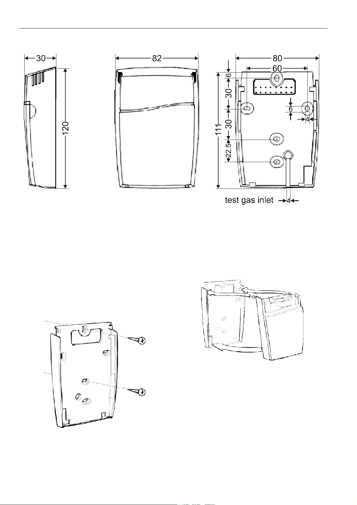
DIMENSIONS
Fig. 1. Dimensions (in mm) of AQS 51/61 (all oval holes have the same size)
WALL MOUNTING
Mounting the Wall Plate
The wall plate mounts vertically on the wall or on the wall
wiring outlet box.
1. Position and level the wall plate on the wall and use a
pencil to mark the mounting holes.
2. Remove the wall plate from the wall, drill two holes for
M4 screws in the wall as marked, and insert dowel into
the holes.
3. Position the wall plate over the holes and pull the wires
through the wiring opening.
4. Loosely insert the mounting screws into the holes and
tighten them (see Fig. 2).
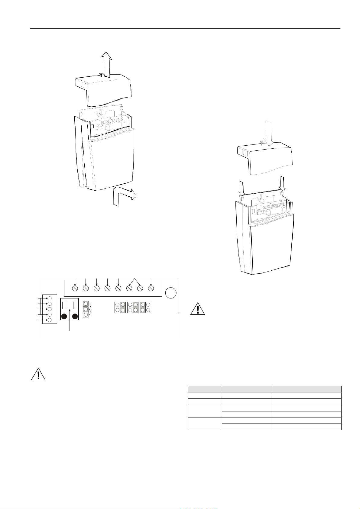
Mounting System Unit onto Wall Plate
1. Bend the wires to the top to allow wiring connections to
the terminals.
2. Engage first the top tabs of the sensor/controller protection case into the top holes of the wall plate and then
press the lower edge of the case onto the wall plate to
latch (see Fig. 3). Be careful not to damage the temperature sensor.
Fig. 3. Mounting the sensor/controller onto the wall plate
Fig. 2. Mounting of the wall plate
EN1B-0189GE51 R0102 2
AQS 51/61 CO2 / TEMPERATURE SENSOR WITH BUILT-IN CONTROLLER
ll
Removing System Unit from Wall Plate
Fig. 4. Removing the wiring terminal cover and the
sensor/controller
1. Loosen the screw on top of the wiring terminal cover and
remove the wiring terminal cover from the wall plate (see
Fig. 4).
2. Pull out first the bottom of the sensor/controller, then
disengage the top tabs and remove the top.
separate floating transformers for sensor and controller /
DDC system.
1. Connect the correct wires to the terminals and securely
tighten each terminal screw. Follow the actual job wiring
diagrams if available or refer to Table 2 for terminal
designations. A sticker is located on the inside of the
terminal cover that identifies the terminals (see Fig. 5).
All wiring must comply with local electrical codes,
ordinances and regulations.
2. Place the wiring terminal cover by fitting the notches of
the cover into the hooks of the wall plate. Tighten the
locking screw (see Fig. 6).
Wiring
y-open
norma
relay
current
voltage
OUT1 OUT2 OUT4
open
current
voltage
collector
voltage
R/T
GND
+5 V
RXD
TXD
G+ G0
digital input
startpoint
selection
jumper
OUT1
0%
20%
OUT2 OUT4M
Fig. 5. Connections and jumpers on AQS51/61. The
shaded positions represent the default settings
CAUTION
Check that all wiring is correctly completed before
turning the power on! Do not connect wires when the
unit is powered. Do not detach the sensor/controller
from the wall plate when the power is on!
The AQS51/61 signal ground (M) is not galvanically
separated from the power supply G0 terminal. If the analog
output signals are connected to controllers or DDC systems,
these units must have the same ground. If necessary, use
Fig. 6. Installing the wiring terminal cover
Electrical Connections
CAUTION
The power supply must be connected to G+ and G0.
G0 is considered as system ground. If the analog
output is connected to a controller, the same ground
reference must be used for the AQS51/61 unit and for
the control system! Unless different transformers are
used, special precautions must be taken!
NOTE: The signal ground of the AQS 51/61 is not
Terminal Default output Default output range
OUT1 0...10 Vdc 0...2000 ppm CO
OUT2 0...10 Vdc 0...50 °C
Relay
OUT4
galvanically separated from its power supply!
Table 1. Default output configurations for AQS51/61
2
closed > 1000 ppm CO
open < 900 ppm CO
closed > 2000 ppm CO
open < 1900 ppm CO
2
2
2
2
EN1B-0189GE51 R01023
 Loading...