

Honeywell AGF1 User Manual
AGF1
WASTE GAS TEMPERATURE SENSOR
PRODUCT DATA
FEATURES
The waste gas temperature sensor AGF1 is suitable for
measuring waste gas in the flue gas pipe.#
The measured waste gas temperature can for instance be
used for the following functions:
• Monitoring of waste gas temperature
• Determining switching on/off times of the burner
• Determining fuel consumption
• Calculating waste gas loss from the heat generator
• Metering the running time of the burner
In order to find out which of the above functions are possible,
consult the instructions of the controller to which the waste
gas sensor is connected.
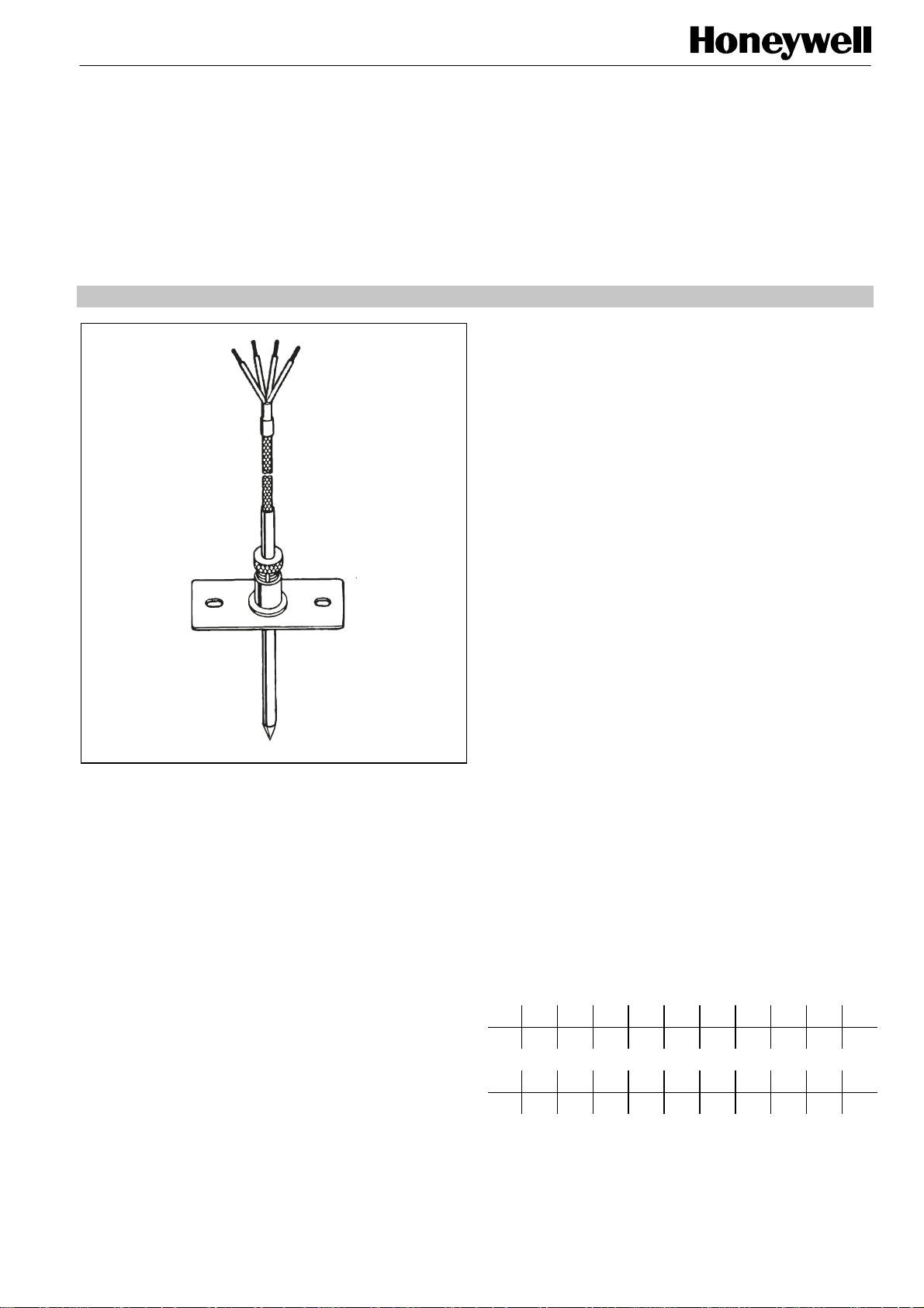
The AGF 1 is designed as a conduit sensor to measure the
waste gas temperature.
SPECIFICATION
Temperature measurement
and range of application 0...320 °C
Sensor element PT 1000 (1000 Ω at 0 °C)
Construction Rod sensor with fitting for
Dimensions Sensor shaft ∅ 5 mm
Max. cable length 100 m at ∅ 1.5 mm²
The resistance of the waste gas temperature sensor AGF 1
depends on the temperature (according to DIN 43 760):
°C 0 20 50 100 110 120 130 140 150 160
1000 1078 1194 1385 1423 1461 1498 1536 1573 1610
Ω
°C 170 180 190 200 210 220 230 250 300 320
(short-time upper limit 400 °C)
according to DIN 43 760
mounting on waste gas pipe
Length 180 mm
Length of terminal cable 1 m
1648 1685 1722 1758 1795 1832 1868 1941 2120 2191
Ω
EN3R-1104 GE51 R0897
AGF1
A
d
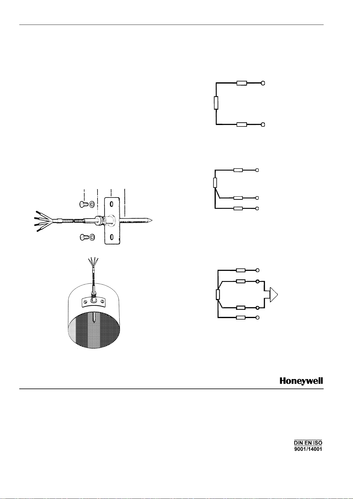
MOUNTING
1. Loosen locking screw B and pull out the sensor element D
from the guiding pipe.
2. Drill a 10 mm Þ hole at the position chosen on the gas
pipe. Take care that the hole for the sensor element is
near the heat generator (ca. 10 – 40 cm behind supports
for the boiler waste gas).
3. Fit the plate C of the waste pipe so that it lies on the pipe.
4. Mark and drill the holes 3.0 mm Þ for the screws supplied.
5. Insert the sensor element into the guiding pipe.
6. Adjustment
The measurement of the waste gas temperature must be
carried out in the core of the waste gas stream (hottest
zone). Furthermore, it must be ensured that the swirling of
waste gas in the pipe has taken place. By inserting the
sensor elelment D at various depths and by repeated
measuring of the waste gas temperature, the hottest zone
will be found. The temperatures can be read in the display
on the digital controller (see instructions).
7. When then hottest zone has been found, the sensor shaft
is fixed into position by tightening the locking screw B.
ABCD
ELECTRICAL CONNECTION
There is a three-prong connection in the controller.
The wiring of the temperature sensor has to be in accordance
with the overall wiring circuit diagram.
red
RL
GF 1
white
white
re
red
RL
power supply
+
white
Advantage: only two cables
Disadvantage: the cable resistance RL distorts the
measurement.
Three cable connection
red
AGF 1
Advantage: the cable resistance is taken into account by
the electronic evaluation and there is no
distorbtion in the measurement.
Disadvantage: three cables are necessary and all must have
the same resistance.
Four cable connection
AGF 1
white
white
Advantage: the cable resistance has no bearing on the
results due to the electronic compensation
(current demand and high ohmic voltage
level). The measurement is not distorted and
the cables can have different resistances.
Disadvantage: four cables are necessary
Home and Building Control Products
Honeywell AG
Böblinger Straβe 17
D-71101 Schönaich
Phone: (49) 7031 63701
Fax: (49) 7031 637493
http://europe.hbc.honeywell.com
Subject to change without notice. Printed in Germany Manufacturing location certified to
EN3R-1104 GE51 R0897
measurement
-
 Loading...