

Honeywell DAF20, AF20 DATASHEET
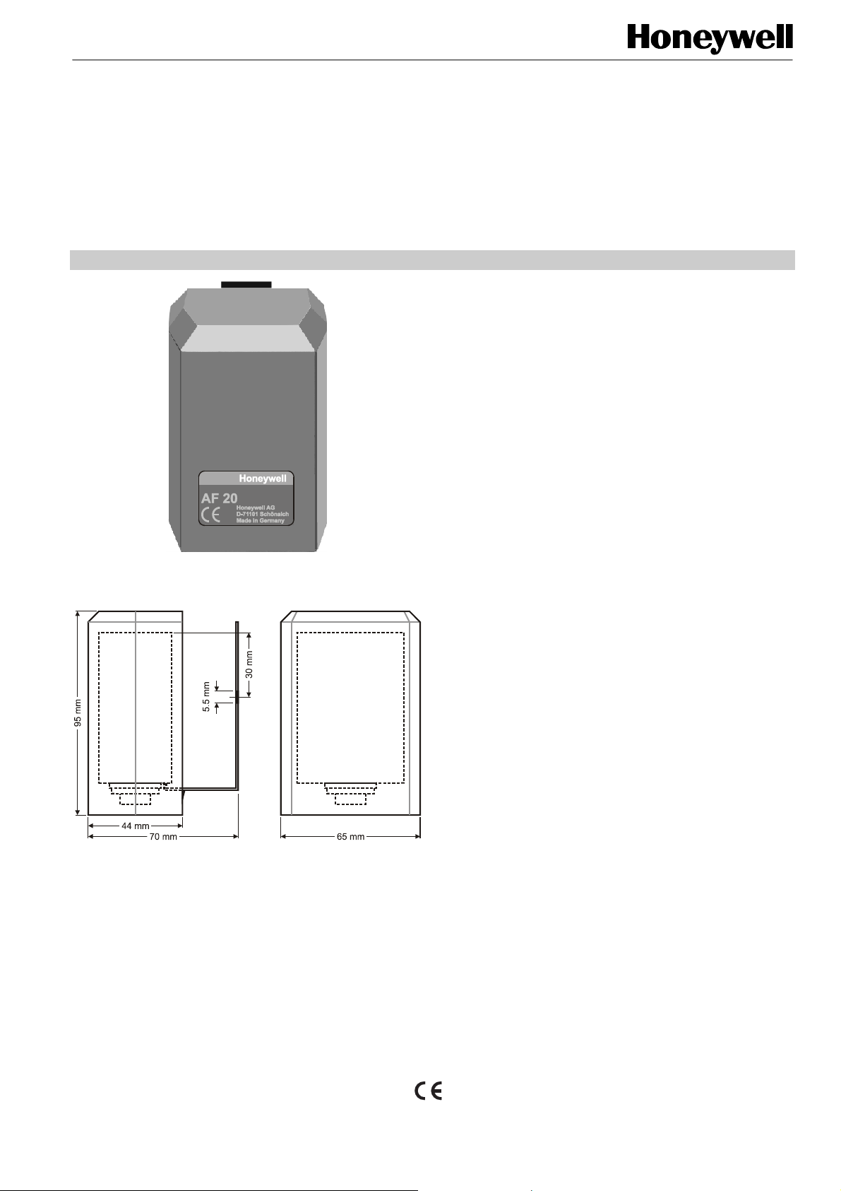
DIMENSIONS
Fig. 1. Dimensions (mm)
AF20 / DAF20
OUTDOOR TEMPERATURE SENSOR
PRODUCT DATA
APPLICATION
Outdoor temperature sensor to detect outside temperature for
weather-related supply air temperature control.
FEATURES
• Sun blinds to protect against radiant heat
• Switch for two separate control devices or heating
groups with DAF 20
TYPES
• AF 20, consisting of one sensor element
• DAF 20, same as AF 20, but consisting of two separate
sensor elements
SPECIFICATIONS
Sensor element NTC thermistor
Resistance 20 Kohm at 25 °C
Operating range -30...+60 °C
Dimensions (H x W x D) 95 x 65 x 70 mm
Housing Plastic (ABS)
Mounting Wall mounting
Electrical connection
AF 20 Electrical terminals for
2 x 1.5 mm² cable
DAF 20 Electrical terminals for
4 x 1.5 mm² cable
Protection class IP 30, DIN 40 050 or IEC 144
For technical information on the NTC thermistor, see
"Temperature Sensors" (EN0B-0476GE51).
® U.S. Registered Trademark EN3R-1107GE51 R0608
Copyright © 2008 Honeywell Inc. • All rights reserved
AF20/DAF20
LOCATION OF DEVICE
The most important rule for locating the outdoor temperature
sensor is that it should have the same temperature, wind, and
solar conditions as the occupied rooms. In most cases, the
outdoor temperature sensor is to be mounted on the coldest
side of the building (N–NW side) so as not to be affected by
direct sunshine. This is to ensure that it will be warm enough
in each room of the house. Only when the windows of all the
rooms to be regulated face in the same direction can the
sensor element be mounted onto the outside of this same
wall. This can also be the south side of the house. The outdoor temperature sensor's protective housing prevents the
sun's rays from affecting the sensor. If the sensor has been
mounted on the south side of a house with large windows
facing in this direction, it is recommended that you remove the
sun guard. Do not mount the outdoor temperature sensor in a
protected area, such as a wall niche or under the balcony. It
should be put on an open façade so that it can detect all
weather conditions. Avoid mounting the sensor above doors
and windows since warm air movements may otherwise
influence the measurement results. The temperature sensor
should be mounted about 2/3 the way up the wall on buildings
of not more that 3 stories; on taller buildings, between the
second and third stories.
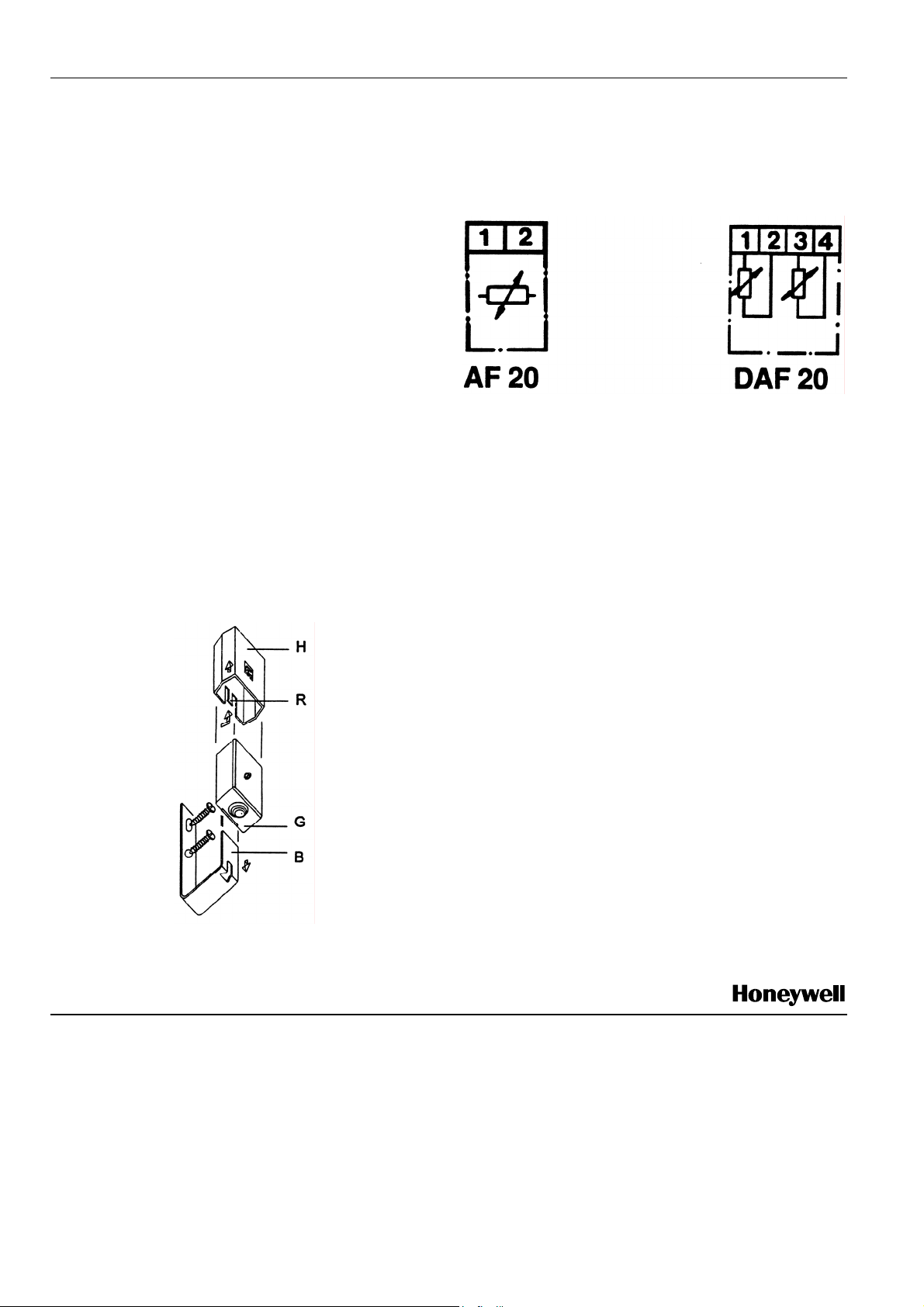
MOUNTING
Press in the clasp (R) and pull off the top (H). Pull the clip (B)
out of the housing (G). Screw on the clip (B) and put on the
housing. To wire, unscrew the lid. Slide the top (H) over the
housing until the clasp is firmly attached.
ELECTRICAL CONNECTION
The wiring of the outdoor temperature sensor AF 20 has to be
in accordance with the overall wiring circuit diagram. The
terminals are not polarized so in the event of the wires
connected in reverse, no malfunction will occur.
Fig. 3. Electrical connection
Fig. 2. Mounting
Manufactured for and on behalf of the Environmental and Combustion Controls Division of Honeywell Technologies Sàrl, Ecublens, Route du Bois 37, Switzerland by its Authorized Representative:
Automation and Control Solutions
Honeywell GmbH
Böblinger Strasse 17
71101 Schönaich / Germany
Phone: (49) 7031 63701
Fax: (49) 7031 637493
http://ecc.emea.honeywell.com
Subject to change without notice. Printed in Germany
EN3R-1107GE51 R0608
 Loading...