

Honeywell 7850L0GE, 7850PGE, 7850LPGE User Manual

®
Dolphin
With Windows Mobile® 5.0
User’s Guide–Preliminary
7850 Mobile Computer

Disclaimer
Honeywell International Inc. (“Honeywell”) reserves the right to make changes in specifications and other
information contained in this document without prior notice, and the reader should in all cases consult
Honeywell to determine whether any such changes have been made. The information in this publicat ion
does not represent a commitment on the part of Honeywell.
Honeywell shall not be liable for technical or editorial errors or omissions contained herein; nor for
incidental or consequential damages resulting from the furnishing, performance, or use of this material.
This document contains proprietary information that is protecte d by copyright. All rights are reserved. No
part of this document may be photocopied, reproduced, or translated into another language without the
prior written consent of Honeywell.
©2006–2008 Honeywell International Inc. All rights reserved.
Web Address: www.honeywell.com/aidc
Trademarks
Dolphin, Dolphin RF, HomeBase, Mobile Base, and QuadCharger are trademarks or registered
trademarks of Hand Held Products, Inc. or Honeywell International Inc.
Microsoft, Windows, Windows Mobile, Windows CE, Windows NT, Windows 2000, Windows ME,
Windows XP, ActiveSync, Outlook, and the Windows logo are trademarks or registered trademarks of
Microsoft Corporation.
Other product names mentioned in this manual may be trademarks or registered trademarks of their
respective companies and are the property of their respective owners.
Patents
Please refer to the product packaging for a list of patents.
Other Trademarks
The Bluetooth trademarks are owned by Bluetooth SIG, Inc., U.S.A. and licensed to Honeywell
International Inc.

Table of Contents
Chapter 1 - Agency Information
Label Locations....................................................................................................................1-1
Regulatory and Safety Approvals for all Dolphin Terminals ................................................1-2
FCC Compliance..................................................................................................................1-3
Chapter 2 - Getting Started
Out of the Box......................................................................................................................2-1
Today Screen.......................................................................................................................2-2
Navigation Bar .....................................................................................................................2-2
Using the Stylus...................................................................................................................2-3
Pop-Up Menus.....................................................................................................................2-3
Chapter 3 - Hardware Overview
Standard Terminal Configuration.........................................................................................3-1
Peripherals...........................................................................................................................3-2
Accessories..........................................................................................................................3-3
Front Panel Features ...........................................................................................................3-4
Back Panel Features............................................................................................................3-5
Side Panel Features ............................................................................................................3-6
Battery Door Tether (Optional).......................................................................................3-7
I/O Connector.......................................................................................................................3-9
Rubber Bumpers................................................................................................................3-10
Battery Power ....................................................................................................................3-11
Main Battery Pack........................................................................................................3-11
Internal Backup Battery................................................................................................3-12
Resetting the Terminal.......................................................................................................3-15
Soft Reset (Warm Boot)...............................................................................................3-15
Hard Reset (Cold Boot)................................................................................................3-15
Suspend Mode...................................................................................................................3-15
Technical Specifications ....................................................................................................3-17
Chapter 4 - Using the Keyboards
Overview..............................................................................................................................4-1
Using the Function Keys......................................................................................................4-2
Using the Navigation Keys...................................................................................................4-3
Using the Modifier Keys.......................................................................................................4-3
Keyboard Mode Indicator.....................................................................................................4-3
24-Key Keyboard .................................................................................................................4-4
Toggling Between Alpha and Numeric Modes...............................................................4-4
24-Key Keyboard Numeric Key Combinations.....................................................................4-5
24-Key Keyboard Alpha Key Combinations.........................................................................4-6
38-Key Keyboard .................................................................................................................4-7
Toggling Between Numeric and Alpha Modes...............................................................4-7
38-Key Keyboard Alpha Key Combinations.........................................................................4-8
38-Key Keyboard Numeric Key Combinations...................................................................4-10
Dolphin® 7850 Mobile Computer User’s
Guide–Preliminary
Rev (d): Preliminary
7/15/2008
iii

Chapter 5 - Using the Imager Scanner Engine
Overview..............................................................................................................................5-1
Available Engines................................................................................................................5-1
Available Laser Engines......................................................................................................5-2
Supported Bar Code Symbologies .....................................................................................5-3
Activating the Engine...........................................................................................................5-4
Decoding .............................................................................................................................5-5
Capturing Images................................................................................................................5-7
Chapter 6 - System Settings
Overview..............................................................................................................................6-1
Personal Settings ................................................................................................................6-2
Buttons...........................................................................................................................6-3
Menus - Modifying the Start Menu.................................................................................6-5
System Settings...................................................................................................................6-7
About .............................................................................................................................6-7
Backlight........................................................................................................................6-8
Memory........................................................................................................................6-10
Power...........................................................................................................................6-12
Remove Programs.......................................................................................................6-14
Screen .........................................................................................................................6-15
Chapter 7 - Communication
Communication Options......................................................................................................7-1
Default Com Port Assignments ...........................................................................................7-2
Installing Additional Software ..............................................................................................7-2
Using ActiveSync.................................................................................................................7-3
Adding Programs via ActiveSync...................................................................................7-4
Connections Tab .................................................................................................................7-6
Connecting the Terminal to a Wireless Network .................................................................7-7
Connecting the Terminal to an ISP......................................................................................7-7
Adding Programs From the Internet....................................................................................7-7
Using Infrared Communication............................................................................................7-8
Connections Manager .......................................................................................................7-10
Network Cards...................................................................................................................7-12
Radio Manager..................................................................................................................7-13
USB to PC.........................................................................................................................7-15
Chapter 8 - Wireless PAN Communication with Bluetooth
Bluetooth Radio...................................................................................................................8-1
Enabling the Bluetooth Radio........................................................................................8-1
BTExplorer...........................................................................................................................8-1
Accessing BTExplorer ...................................................................................................8-2
Using BTExplorer ................................................................................................................8-3
Connection Types................................................................................................................8-7
Device Types.......................................................................................................................8-8
View Options .......................................................................................................................8-8
Menu Options......................................................................................................................8-9
iv Rev (d): Preliminary
7/15/2008
Dolphin® 7850 Mobile Computer
User’s Guide–Preliminary

Discovered Devices...........................................................................................................8-10
Refreshing Discovered Devices...................................................................................8-10
Making the Terminal Discoverable ..............................................................................8-10
Pairing ...............................................................................................................................8-13
Chapter 9 - Dolphin HomeBase Device
Overview..............................................................................................................................9-1
Front Panel .........................................................................................................................9-2
Back Panel .........................................................................................................................9-3
Bottom Panel Dimensions...................................................................................................9-4
Powering the HomeBase Device.........................................................................................9-5
Charging the Main Battery...................................................................................................9-7
ActiveSync Communication.................................................................................................9-8
RS-232 Cables....................................................................................................................9-9
Mounting the Dolphin HomeBase Device..........................................................................9-10
Chapter 10 - Dolphin QuadCharger Device
Overview............................................................................................................................10-1
Front Panel .......................................................................................................................10-2
Back Panel ........................................................................................................................10-3
Inserting and Removing Battery Packs .............................................................................10-3
Supplying Power to the QuadCharger Device...................................................................10-3
Charging Batteries.............................................................................................................10-4
Recommendations for Storing Batteries............................................................................10-4
Using the Battery Analyzer................................................................................................10-5
Bottom Panel.....................................................................................................................10-6
Mounting the QuadCharger Device...................................................................................10-6
Troubleshooting.................................................................................................................10-7
Chapter 11 - Dolphin ChargeBase
Overview............................................................................................................................11-1
Front Panel .......................................................................................................................11-2
Back Panel ........................................................................................................................11-3
Power Supply...............................................................................................................11-3
Supplying Power to the ChargeBase.................................................................................11-4
Inserting and Removing Terminals....................................................................................11-4
Charging Terminals in the ChargeBase ............................................................................11-5
Mounting the ChargeBase.................................................................................................11-6
Chapter 12 - Cables Kits
Universal Cable Features..................................................................................................12-1
Using the Power Cable......................................................................................................12-2
Using the Mobile Charger..................................................................................................12-3
Using the Charge/Comm Cable.........................................................................................12-4
Chapter 13 - Customer Support and Warranty
Technical Assistance.........................................................................................................13-1
Product Service and Repair...............................................................................................13-2
Dolphin® 7850 Mobile Computer User’s
Guide–Preliminary
Rev (d): Preliminary
7/15/2008
v

Limited Warranty ...............................................................................................................13-2
vi Rev (d): Preliminary
7/15/2008
Dolphin® 7850 Mobile Computer
User’s Guide–Preliminary
1
Compliance Label
Laser Safety Label
Agency Information
Label Locations
Dolphin 7850 mobile computers meet or exceed the requirements of all applicable standards
organizations for safe operation. However, as with any electrical equipment, the best way to ensure safe
operation is to operate them according to the agency guidelines that follow. Please read these guidelines
carefully before using your Dolphin mobile computer.
Dolphin 7850 802.11b/g (WLAN) & Bluetooth
Dolphin 7850 RF terminals are designed to comply with the most current applicable standards on safe
levels of RF energy developed by the Institute of Electrical and Electronics Engineers (IEEE) and the
American National Standards Institute (ANSI) and has been recommended for adoption by the Federal
Communications Commission (FCC).
R&TTE Compliance Statement—802.11b/g (WLAN) and/or Bluetooth
Dolphin RF terminals are in conformity with all essential requirements of the R&TTE Directive (1999/5/
EC). This equipment has been assessed to the following standards as applicable:
Parameter Specification
R&TTE EN 300 328-2:2000
EN 301 489-1 (2002-08)
EN 301 489-17 (2002-08)
EN 60950:2000
EN 50361:2001
This product is marked with in accordance with the Class II product requirements specified in
the R&TTE Directive, 1999/5/EC.
The equipment is intended for use throughout the European Community. PAN European Frequency
Range: 2.402—2.480 GHz. Restrictions in France are as follows:
• Indoor use: Maximum power (EIRP*) of 100 mW for the entire 2.400—2.4835 GHz
• Outdoor use: Maximum power (EIRP*) of 100 mW for the 2.400—2.454 GHz band and maximum
power (EIRP*) of 10 mW for the 2.454—2.483 GHz band
For further information, please contact:
Honeywell Imaging & Mobility Europe BV
Nijverheidsweg 9
5627 BT Eindhoven
The Netherlands
Honeywell shall not be liable for use of our product with equipment (i.e., power supplies, personal
computers, etc.) that is not CE marked and does not comply with the Low Voltage Directive.
Dolphin® 7850 Mobile Computer
User’s Guide–Preliminary
Rev (d): Preliminary
7/15/2008
1 - 1
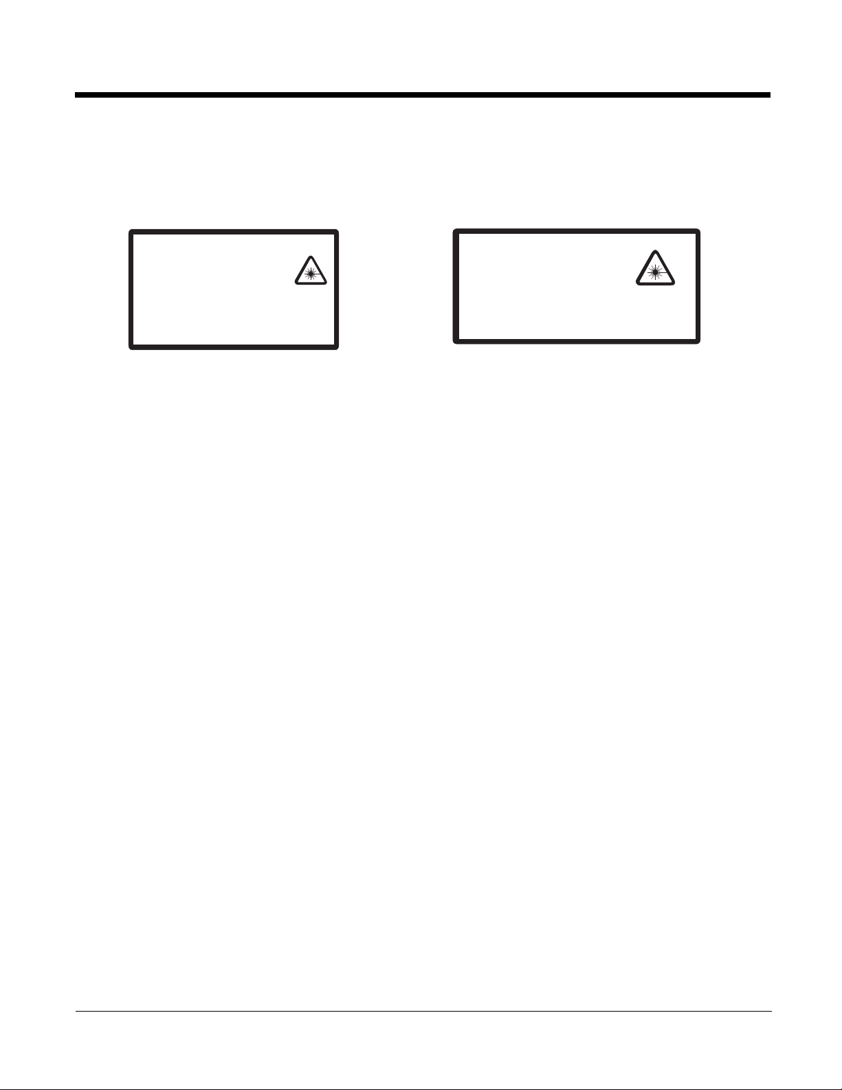
Laser Safety Label
LASER LIGHT. DO NOT STAR E INTO BEAM
1.0 mW MAX OUTPUT: 650nM
IE C60825- 1: 1993 + A1 + A2
CLASS2LASERPRODUCT
Compli es with 21 CFR 1040. 10 and 1040. 11
except for deviations pursuant to Las er
Notic e No. 50, da ted J une 24, 2007. P uls e
durati on = 35+/- 5 S ca ns/S ec.
LASER LIGHT. DO NOT STARE INTO BEAM
1.0 mW MAX OUTPUT: 650nM
IEC60825-1:1993+A1+A2
CLASS 2 LASER PRODUCT
Complies with 21 CFR 1040.10 and 1040.1 1
except for deviations pursuant to Laser
Notice No. 50, dated July 26, 2001.
SE1200 Laser Scan Engine Image Engines with Integrated Laser Aimers
If the following label is attached to your product, it indicates the product contains a laser engine or laser
aimer:
Laser Eye Safety Statement: This device has been tested in accordance with and complies with
EN60825-1: 1993+A1+A2 and 21 CFR 1040.10 and 1040.11, except for deviations pursuant to Laser
Notice No. 50, dated July 26, 2001. LASER LIGHT, DO NOT STARE INTO BEAM, CLASS 2 LASER
PRODUCT, 1.0 mW MAX OUTPUT: 650nM.
Caution - use of controls or adjustments or performance of procedures other than those specified herein
may result in hazardous radiation exposure.
LED Safety Statement
This device has been tested in accordance with IEC60825-1 LED safety, and has been certified to be
under the limits of a Class 1 LED device.
The maximum power outputs for each diode are as follows:
• Illumination LED: 194.0 uW
• Aimer laser (5300 engine): 360.1 uW
• Aimer LED (5100 engine): 81.6 uW
Infrared LED Safety Statement
Caution - Class 1M LED radiation when open. Do not view directly with optical instruments.
The maximum power outputs for the IR LED is 145.1 uW.
UL and cUL Statement
UL and cUL listed: UL60950-1 and CSA C22.2 No. 60950-1-03.
1 - 2 Rev (d): Preliminary
7/15/2008
Dolphin® 7850 Mobile Computer
User’s Guide–Preliminary

Regulatory and Safety Approvals for all Dolphin Terminals
Parameter Specification
U.S.A. FCC Part 15, Class B
Canada ICES-003
European Community EN 55022 (CISPR 22) Class B
EN60950:2000
EN60825-1:1994 + A11 + A2
EN55024:1998
The CE Mark on the product indicates that the system has been tested to and conforms with the
provisions noted within the 89/336/EEC Electromagnetic Compatibility Directive and the 73/23/
EEC and 93/68/EEC Low Voltage Directive.
Dolphin RF Te rminal—802.11b/g (WLAN) and/or Bluetooth
This device complies with Part 15 of the FCC Rules. Operation is subject to the following two conditions:
(1) this device may not cause harmful interference, and (2) this device must accept any interference
received, including interference that may cause undesired operation.
This equipment has been tested and found to comply with the limits for a Class B digital device pursuant
to Part 15 of the FCC Rules. These limits a re designed to provide reason able protection against harmful
interference in a residential installation. This equipment generates, uses, and can rad iate radio frequency
energy and, if not installed and used in accordance with the instructions, may cause harmful interfere nce
to radio communications. However, there is no guarantee that interference will not occur in a particular
installation. If this equipment does cause harmful interference to radio or television reception, which can
be determined by turning the equipment off and on, the user is encouraged to try to correct the
interference by one or more of the following measures:
• Reorient or relocate the receiving antenna.
• Increase the separation between the equipment and receiver.
• Connect the equipment into an outlet on a circuit different from that to which the receiver is connected.
• Consult the dealer or an experienced radio/TV technician for help.
If necessary, the user should consult the dealer or an experienced radio/television technician for
additional suggestions. The user may find the following booklet helpful: “Something About Int erference.”
This is available at FCC local regional offices. Our company is not responsible for any ra dio or television
interference caused by unauthorized modifications of this equipment or the substitution or attachment of
connecting cables and equipment other than those specified by our company. The correction is the
responsibility of the user. Use only shielded data cables with this system.
In accordance with FCC 15.21, changes or modifications not expressly approv ed by Honeywell may void
the FCC authorization to operate the equipment.
CAUTION! Any changes or modifications not expressly approved by the grantee of this device could
void the user's authority to operate the equipment.
For body worn operation, this device has been tested and meets the FCC RF exposure guidelines when
used with the Honeywell Dolphin accessories supplied or designated for this product. Use of other
accessories may not ensure compliance with FCC RF exposure guidelines.
Dolphin® 7850 Mobile Computer
User’s Guide–Preliminary
Rev (d): Preliminary
7/15/2008
1 - 3

RF, Regulatory, and Safety Agency Approvals—802.11b/g (WLAN) and/or Bluetooth
Parameter Specification
U.S.A. FCC Part 15.247
Canada RSS 210
Canadian Compliance
This Class B digital apparatus complies with Canadian ICES-003. Operation is subject to the following
two conditions: (1) this device may not cause harmful interference, and (2) this device must accept any
interference received, including interference that may cause undesired operation.
To prevent radio interference to the licensed service, this device is intended to be operated indoors and
away from windows to provide maximum shielding. Equipment (or its transmit antenna) installed outdoors
is subject to licensing.
Cet appareil numérique de la Classe B est conforme à la norme NMB-003 du Canada.
For European Community Users
Honeywell complies with Directive 2002/96/EC OF THE EUROPEAN PARLIAMENT AND OF THE
COUNCIL of 27 January 2003 on waste electrical and electronic equipment (WEEE).
Waste Electrical and Electronic Equipment Information
This product has required the extraction and use of natural resources for its production. It may contain
hazardous substances that could impact health and the environment, if not properly disposed.
In order to avoid the dissemination of those substances in our environment and to diminish the pressure
on the natural resources, we encourage you to use the appropriate take-back systems for product
disposal. Those systems will reuse or recycle most of the materials of the product you are disposing in a
sound way.
The crossed out wheeled bin symbol informs you that the product should not be disposed of along
with municipal waste and invites you to use the appropria te separate take-back systems for product
disposal.
If you need more information on the collection, reuse, and recycling systems, please contact your local or
regional waste administration.
You may also contact your supplier for more information on the environmental performances of this
product.
Pacemakers, Hearing Aids and Other Electrically Powered Devices
Most manufacturers of medical devices adhere to the IEC 601-1-2 standard. This standard requires
devices to operate properly in an EM Field with a strength of 3V/m over a frequency range of 26 to
1000MHz. The maximum allowable field strength emitted b y the Dolphin terminal is 0.3V/m according to
Subpart B of Part 1 of the FCC rules. Therefore, the Dolphin RF terminal has no effect on medical devices
that meet the IEC specification.
1 - 4 Rev (d): Preliminary
7/15/2008
Dolphin® 7850 Mobile Computer
User’s Guide–Preliminary

Microwaves
The radio in the Dolphin RF terminal operates on the same frequency band as a microwave oven.
Therefore, if you use a microwave within range of the Dolphin RF terminal you may notice performance
degradation in your wireless network. However, both your microwave and your wireless network will
continue to function. The Dolphin Batch terminal does not contain a radio, and therefore, is not affected
by microwave ovens.
Dolphin® 7850 Mobile Computer
User’s Guide–Preliminary
Rev (d): Preliminary
7/15/2008
1 - 5

1 - 6 Rev (d): Preliminary
7/15/2008
Dolphin® 7850 Mobile Computer
User’s Guide–Preliminary
2
Mechanical Switch
!
Getting Started
Out of the Box
When you open the carton, please verify that the carton contains the following items:
• Dolphin 7850 mobile computer (the terminal)
• Main battery pack (7.4v, li-ion)
• Getting Started CD-ROM
• Dolphin 7850 Mobile Computer Quick Start Guide
Be sure to keep the original packaging in the event that the Dolphin termina l should need to be returned
for service. For details, see Limited Warranty on page 13-2.
If you ordered additional peripherals and accessories, verify that they are included with the order.
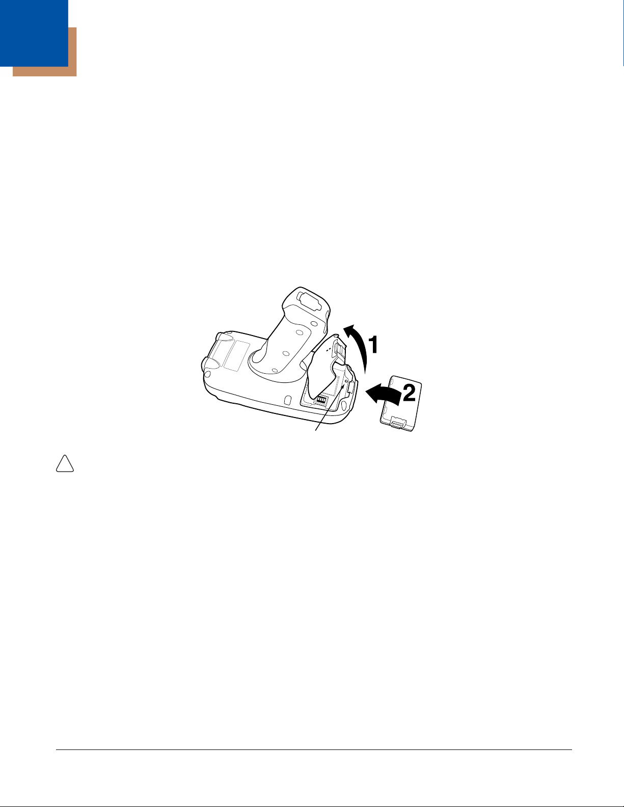
Step 1. Install the Main Battery Pack
You must re-attach the battery door! This terminal contains a mechanical switch under the battery door that prevents
the terminal from initializing unless the battery door is closed.
Step 2. Charge the Batteries
There are two types of battery power: the main battery pack and the backup battery located inside the
terminal. The main battery pack powers the terminal and charges the internal backup battery.
Dolphin terminals ship with both batteries discharged of power. Charge the main battery pack for a
minimum of four(4) hours before initial use!
You can use one of the following charging peripherals:
• Dolphin HomeBase Device
• Dolphin QuadCharger Device
• AC Adapter Cable
Step 3. Boot the Terminal
The terminal begins booting as soon as power is applied and runs by itself. Do NOT press any keys or
interrupt the boot process.
When the boot process is complete, the Today screen appears and the terminal is ready for use.
Dolphin® 7850 Mobile Computer
User’s Guide–Preliminary
Rev (d): Preliminary
7/15/2008
2 - 1

Today Screen
Tap to adjust the volume
Tap to change the date and time
Tap to access the Start menu
These are icons of programs
running in the background. T ap to
open the program or access a
menu for it.
Tap to see to customize your terminal
Tap to open a program recently used
Tap to open a program
Tap to see additional programs
Navigation bar
Start menu
Initial boot and system resets end on the Today screen; see Resetting the Terminal on page 3-15.
Note: You can also open the Today screen at any time by tapping Start > Today.
Navigation Bar
Located at the top of every screen, the Navigation bar provides access to the Start menu, shows the
current time (from the system clock), and displays both status and keyboard status icons.
Command Bar
Located at the bottom of application screens, the Command bar includes application menus, buttons, and
provides access to the Soft Input Panel (SIP).
The contents of the Command bar changes according to the open application.
2 - 2 Rev (d): Preliminary
7/15/2008
Dolphin® 7850 Mobile Computer
User’s Guide–Preliminary
Using the Stylus
!
Note: To close the menu
without performing an
action, tap the screen
anywhere outside the
menu.
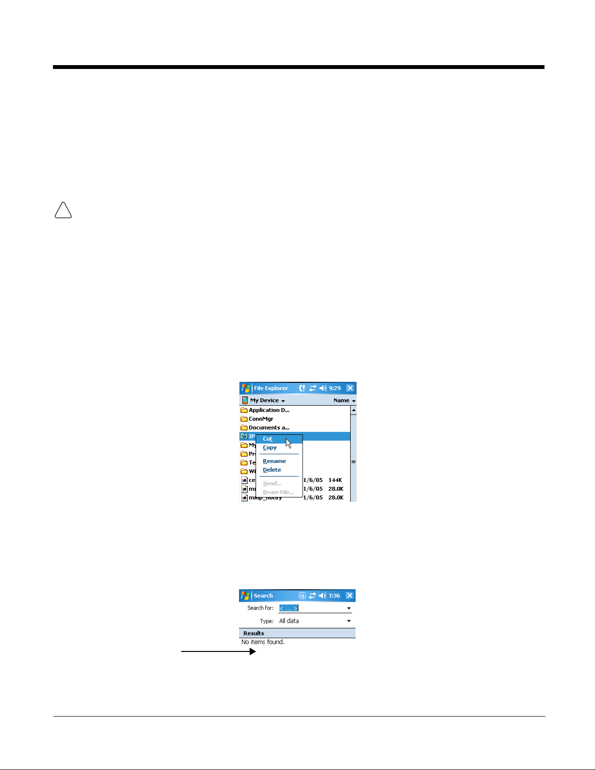
The Results section
displays the search
results.
Use the stylus or your finger to select or enter information on the touch panel. The stylus functions as a
mouse; generally, a tap is the same as a click.
Tap Tap the touch panel once to open menu items and select options.
Drag Hold the stylus on the screen and drag across the screen to select text and images.
Tap & hold Tap and hold the stylus on an item and a pop-up me nu appears. On t he pop-up menu, tap
the action of the task you want to perform.
Using sharp objects, such as paper clips, pencils, or ink pens can damage the touch panel an d may cause
damage not covered by the warranty. For more information about the touch panel, see Touch Panel Display
on page 3-4.
Selecting Programs
The Start menu does not fit all installed programs. To see additional programs, ta p Start > Programs. To
open a program, tap once on the icon.
Pop-Up Men u s
With pop-up menus, you can quickly choose an action for an item.
1. Tap and hold the stylus on the item name. The pop-up menu appears.
2. Lift the stylus, and tap the action you want to perform.
The contents of pop-up menus depend change according to the program you’re in.
Searching fo r Information
You can use the Search feature or File Explorer to find and organize information. Tap Start > Programs
> Search. Enter the text you want to find and tap Search.
Dolphin® 7850 Mobile Computer
User’s Guide–Preliminary
Rev (d): Preliminary
7/15/2008
2 - 3

2 - 4 Rev (d): Preliminary
7/15/2008
Dolphin® 7850 Mobile Computer
User’s Guide–Preliminary

3
Hardware Overvie w
There are a number of standard configurations as well as charging and communication peripherals and
accessories to maximize the efficiency of your application setting.
Standard Terminal Configuration
• Windows Mobile 5.0
• PXA270 520MHz processor
• 64MB RAM X 64MB Synchronous Flash memory
• 24-key calculator-style numeric with scrolling alpha or 38-key calculator-style numeric with full alpha
• 3.5 in. 1/4 VGA 240 x 320 TFT color display with hard-coat industrial touch panel
• 5300 or 5100 Standard Range (SR) scan engine
• WLAN radio (Wi-Fi certified)
• Bluetooth radio
Additional Configuration Options
The Dolphin 7850 terminal offers you a number of configuration options to customize the terminal to your
business needs.
System Memory Additional 64MB of RAM (for a total of 128MB RAM); see Memory on page 6-10.
Scan Engines 5100SR/SF VGA Area Imagers with bright green LED aimer
Laser Engines Options
5300SR/SF VGA Area Imagers with High-Vis aiming patte rn
5300HD VGA Area Imagers with High-Vis aiming pattern
For more information, see Available Engines on page 5-1.
HP (High Performance) Laser scanner
LR (Long Range) Laser scanner
ALR (Advanced Long Range) Laser scanner
For more information, see Available Laser Engines on page 5-2.
Dolphin® 7850 Mobile Computer
User’s Guide–Preliminary
Rev (d): Preliminary
7/15/2008
3 - 1

Peripherals
The following items are sold separately as part of a complete installation.
Dolphin HomeBase™ Device
This charging and communication cradle supports both RS-232 and USB communi cation, enabling your
terminal to interface with the majority of PC-based enterprise systems. When a terminal is seated in the
HomeBase device, its main battery pack charges in less than four(4) hours.
For more information, see Dolphin HomeBase Device on page 9-1.
Dolphin QuadCharger™ Device
This four(4)-slot charging station for Li-ion battery packs can charge each battery in less than four(4)
hours. The fourth slot features a battery analyzer t hat completely resets and re- calibrates a battery, then
displays remaining capacity.
For more information, see Dolphin QuadCharger Device on page 10-1.
Cables Kits
There are a number of cable kits that enable you to charge and communicate with other devices.
For more information, see Cables Kits on page 12-1.
Dolphin ChargeBase
This charging bay holds up to four(4) Dolphin 7850 terminals.
For more information, see Dolphin ChargeBase on page 11-1.
Mobile Mount
The Mobile Mount is a plastic cradle and RAM mount that holds and positions the terminal and can be
mounted on a fork truck, pallet lift, or other stable, stationary surface.
3 - 2 Rev (d): Preliminary
7/15/2008
Dolphin® 7850 Mobile Computer
User’s Guide–Preliminary

Accessories
The following items are sold separately as part of a complete installation.
Battery Door Tether
For more information, see Battery Door Tether (Optional) on page 3-7.
Holster
The holster holds one terminal around the waist.
Li-ion Battery Pack
These are 7.4Vdc, 14.1 watt hour Li-on replacement battery packs; see Battery Power on page 3-11.
Protective Cover
The protective cover wraps around the terminal to protect it from wear and tear.
Protective Rubber Boot
The protective rubber boot wraps tightly around the terminal for added durability.
Screen Protectors
This is a pack of screen protectors that fit the touch panel display.
Stylus Three-Pack
This is a pack of three extra styluses.
Tote/Carry Bag
The tote and carry bag holds one terminal, a spare battery, and small printer. It can be shoulder-worn,
waist-worn, or carried by hand.
Wrist Lanyard/Stylus Tether
For more information, see Wrist Lanyard/Stylus Tether (Optional) on page 3-7.
Dolphin® 7850 Mobile Computer
User’s Guide–Preliminary
Rev (d): Preliminary
7/15/2008
3 - 3
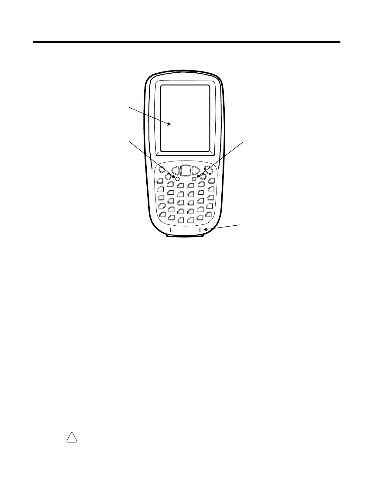
Front Panel Features
Decode LED Scan LED
3.5 inch 1/4 VGA Touch
Panel Display
Keyboard Protection Ribs
!
Decode and Scan LEDs
The Scan LED lights red when you press the Scan trigger in scanning applications.
The Decode LED lights green when a scanned bar code is successfully decoded.
For more information, see LEDs on page 4-1.
Keyboard Protection Ribs
These ribs protect the keyboard and prevent keys from being pressed accidentally when the
terminal is placed facedown on a flat surface. For a complete overview of each keyboard, see
Using the Keyboards on page 4-1.
Touch Panel Display
The 3.5 inch 1/4 VGA (Video Graphic Array) display is a transflective color LCD (Liquid Crystal
Display) in TFT (Thin Film Transistor) color with a 240 x 320 resolution. The LCD is covered
by an industrial touch screen lens for maximum durability and backlit for maximum viewability;
see Backlight on page 6-8.
For touch panel input, use the stylus included with t he terminal or your finger. The method you
choose depends on which one is most appropriate for your application. While there is a great
deal of variation in different applications, use of the supplied stylus provides greater touch
screen accuracy; see Using the Stylus on page 2-3.
Dolphin terminals ship with screen protectors already installed. Screen protectors help prevent
wear and damage to the touch panel; especially when used with applications that require highvolume interfacing with the touch panel. Screen protectors are subject to wear and tear.
Therefore, inspect screen protectors regularly and replace them when worn or punctured.
Using sharp objects, such as paper clips, pencils, or ink pens and may cause damage
not covered by the warranty.
3 - 4 Rev (d): Preliminary
7/15/2008
Dolphin® 7850 Mobile Computer
User’s Guide–Preliminary
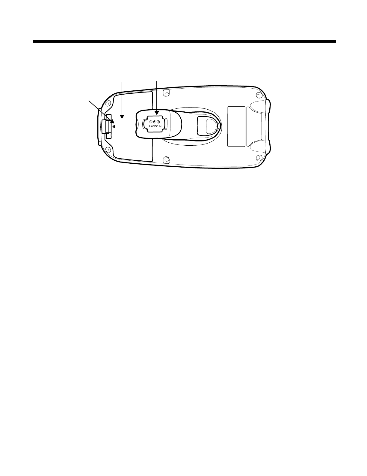
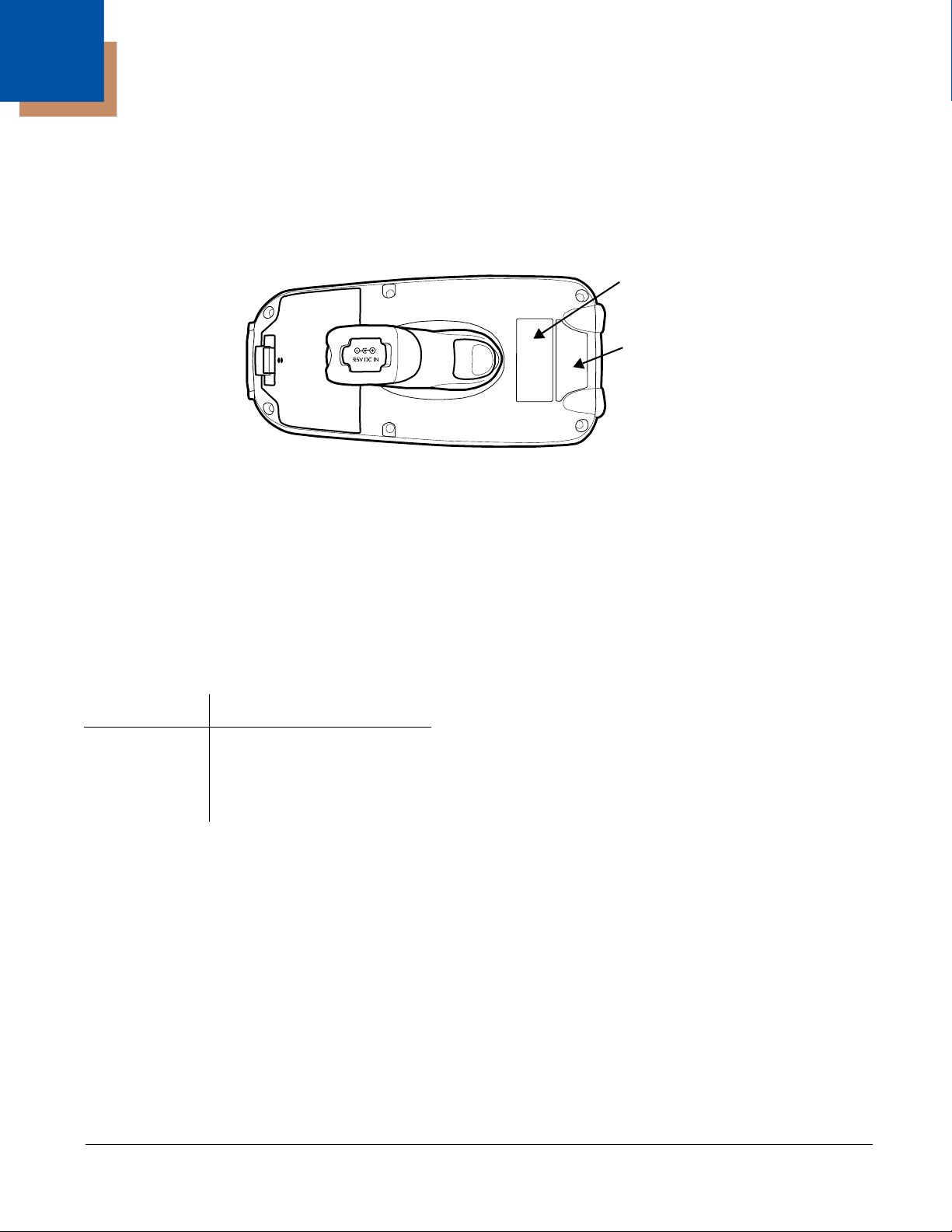
Back Panel Features
Battery Door
DC Power Jack
Tether Holes
Battery Door
The battery door covers and secures the main battery pack in the battery well. There is a
mechanical switch on the terminal under this door that puts the terminal in suspend mode (see
page 3-15) while the ba ttery door is open. This door must be closed for the terminal to resume
operation. For more information, see Installing the Main Battery Pack on page 3-11.
DC Power Jack
Located on the bottom of the pistol-grip handle, the 9.5V DC power jack receives external
power from the Dolphin Power Cable. When connected to the Power Cable, the terminal is
powered and the main battery pack is charging. For more information, see Using the Power
Cable on page 12-2.
Tether Holes
These holes are an attachment point for the Battery Door Tether (Optional) (see page 3-7).
Dolphin® 7850 Mobile Computer
User’s Guide–Preliminary
Rev (d): Preliminary
7/15/2008
3 - 5
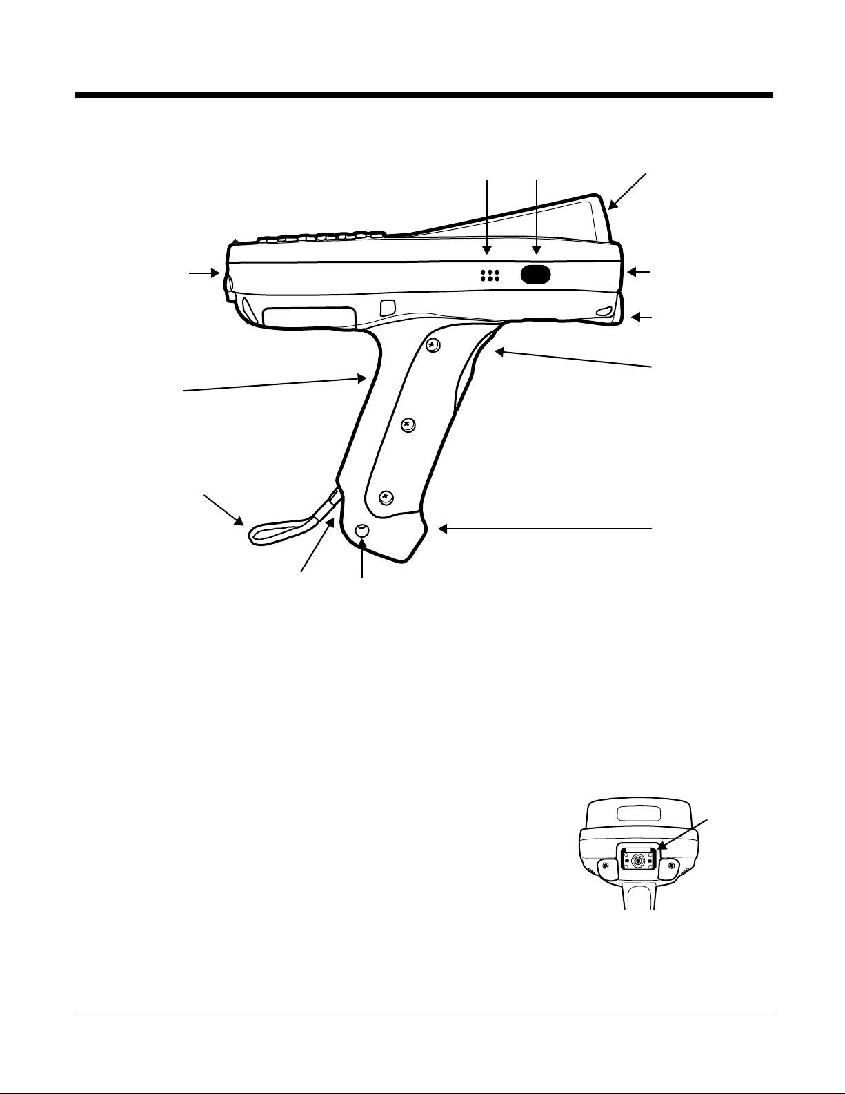
Side Panel Features
Scan
Trigger
Stylus Slot
Integrated
Pistol-Grip
I/O Connector
Scan Engine
Window
Angled Display
IrDA PortBeeper
I/O
Connector
Tether/Lanyard Attachment Point
I/O
Connector
Stylus Loop
Scan
Engine
Window
(with
engine)
Note: This graphic shows the right side of the Dolphin 7850 terminal.
Angled Display
Beeper
Scan Engine Window
Integrated Pistol-Grip Handle
3 - 6 Rev (d): Preliminary
The touch panel display (see page 3-4) tilts up toward the user, which improves application
viewing when operating the terminal and reduces glare. Most important, the tilted display helps
you read decoded data without having to tilt your wrist.
The beeper provides an audible indication of application events such as decoding (to indicate
a good or bad scan), touch panel touches, and keyboard input.
The scan engine window provides an opening for the imager
scanner engines and points straight out of the device. Simply
point and scan.
There are several scan engine configurations available; see
Using the Imager Scanner Engine on page 5-1.
The pistol-grip handle is integrated into the terminal and is not removable, which makes the
unit more durable in the field. This handle is contoured so that the terminal is comfortable in
your hand and balanced during operations.
7/15/2008
Dolphin® 7850 Mobile Computer
User’s Guide–Preliminary

IrDA Port
The infrared port is IrDA-enabled (Infrared Data Association) and communicates with other
IrDA-enabled devices such as PCs, printers, modems, or other Dolphin 7850 terminals. The
maximum data transfer speed is 115 Kbps with a duty cycle of 18.75%. For more informat ion,
see Using Infrared Communication on page 7-8.
Scan Trigger
The front of the pistol-grip handle contains a scan trigger that activates the scan engine.
The scan trigger also wakes the terminal from Suspend Mode (see page 3-15).
Stylus Slot
Dolphin 7850 terminals ship with a stylus inserted into the pistol-grip handle. Stores the stylus
in this slot when you’re not using it. For more information about the stylus, see Using the Stylus
on page 2-3.
Tether/Lanyard Attachment Point
You can string optional hardware accessories through this hole to fasten hardware to the
terminal.
Wrist Lanyard/Stylus Tether (Optional)
The optional lanyard loops around your wrist and attaches the stylus to the terminal. One end loops
through the attachment point at the bottom of the handle and the other end loops around the hook at the
end of the stylus.
When the stylus is inserted into the stylus slot, you can insert your wrist for extra security while operating
the terminal. When the stylus is removed from the stylus slot, the stylus remains attached to the terminal
to prevent you from losing the stylus if you accidently drop it.
Battery Door Tether (Optional)
The optional battery door tether ensures that the battery door remains attached to th e terminal even when
it is removed from the battery well. There are two pieces: the clip and the leather strap.
1. Put the terminal in Suspend mode by pressing and holding Blue + Backlight keys.
2. Disconnect the two pieces of the battery door tether; gently squeeze the outside of the clip and pull
the leather strap out of the clip.
3. Take the leather strap and loop the lanyard portion through the attachment point on the handle as
shown below.
Dolphin® 7850 Mobile Computer
User’s Guide–Preliminary
Rev (d): Preliminary
7/15/2008
3 - 7
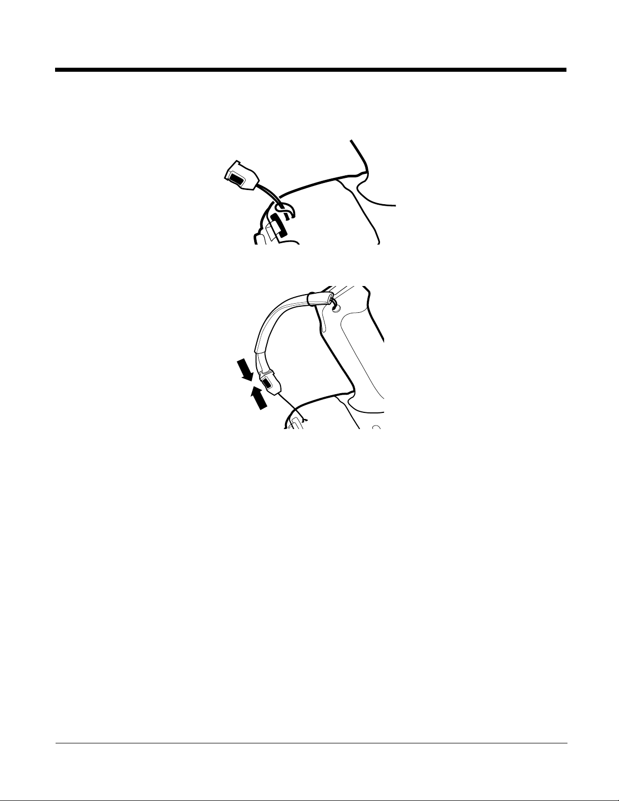
4. Remove the battery door.
5. Take the clip piece, loop the lanyard through the tether holes on the battery door as shown below.
6. Reattach the battery door.
7. Snap the leather strap into the clip.
3 - 8 Rev (d): Preliminary
7/15/2008
Dolphin® 7850 Mobile Computer
User’s Guide–Preliminary
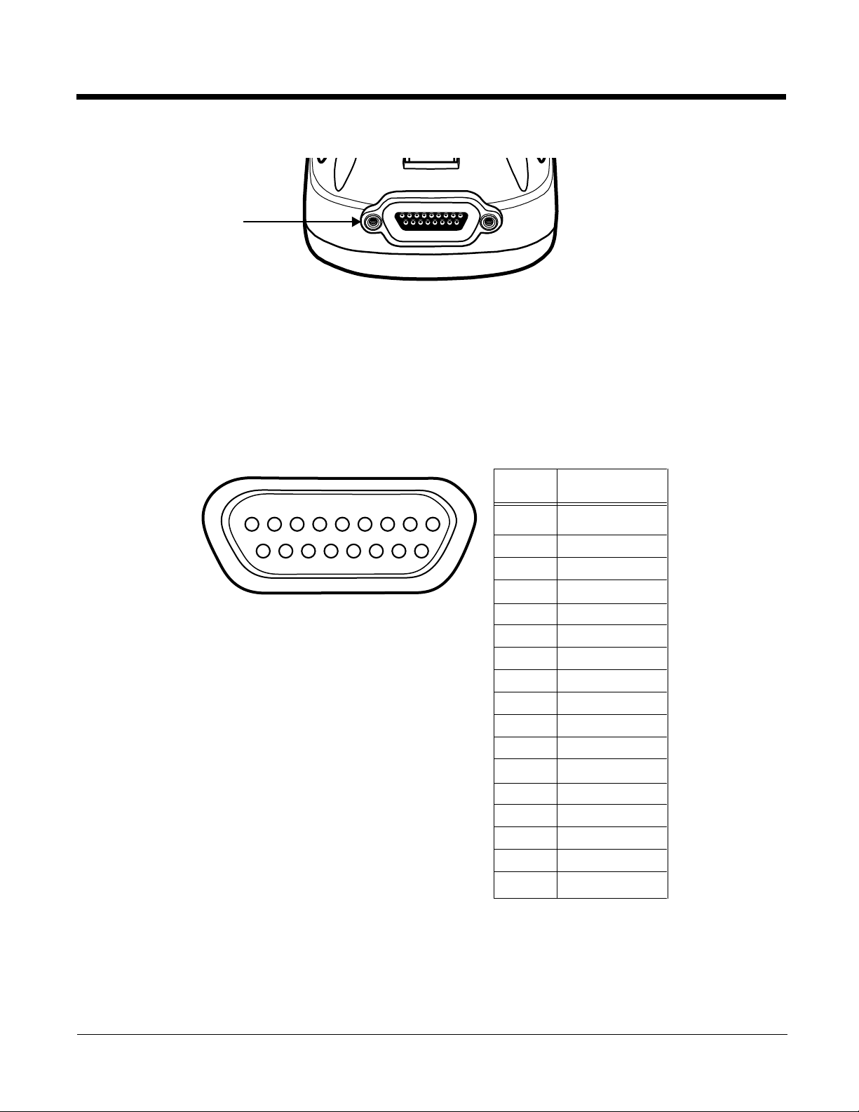
I/O Connector
I/O Connector
0IN$ESCRIPTION
53"
072
.#
.#
.#
.#
'.$
6/54
$42
53"
53"$%4
2)
$32
28$
243
48$
#43
1
10
2
11
3
12
4
13
5
14
6
15
7
16
8
17
9
This I/O connector has 17 pins that are designed to work exclusively with Dolphin 7850 peripherals and
cables. This connector
• Powers the terminal.
• Charges the main battery.
• Supports communication with a host workstation via Microsoft ActiveSync (see page 7-3).
• Supports RS-232 (up to 115 Kbps) and USB (up to 12 Mbps) communication.
The pins on the I/O connector are as follows:
Note: Signals referenced are for a DTE device.
Dolphin® 7850 Mobile Computer
User’s Guide–Preliminary
Rev (d): Preliminary
7/15/2008
3 - 9
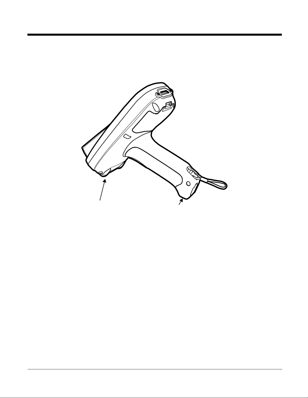
Rubber Bumpers
Front Rubber
Bumpers
Pistol-Grip
Rubber Bumpers
There are two sets of rubber bumpers: one set below the scan engine window and the other set on the
bottom front of the pistol-grip handle. Rubber bumpers enable you to set the terminal down on a flat
surface with easy access to the handle, so you can pick up and put down the terminal with ease.
Front Rubber Bumpers
The front rubber bumpers enable you to rest the terminal on a flat surface without damaging
the scan engine window.
3 - 10 Rev (d): Preliminary
7/15/2008
Dolphin® 7850 Mobile Computer
User’s Guide–Preliminary
Battery Power
!
Mechanical Switch
The intelligent battery technology built into the terminal features two types of battery power:
• The main battery pack installed under the battery door on the back panel.
• The backup battery located inside the terminal.
Both batteries work together to prevent data loss when the terminal is used over long periods of time.
Main Battery Pack
Use only the Li-ion battery packs provided by Honeywell. Use of any battery not sold/manufactured by
Honeywell may result in damage not covered by the warranty.
The 7.4V, 14.1 watt hour li-ion battery pack is the primary power source for the Dolphin terminal and the
internal backup battery. The li-ion battery is designed to operate in a temperature range of -10 to 50°C
(14 to 122°F).
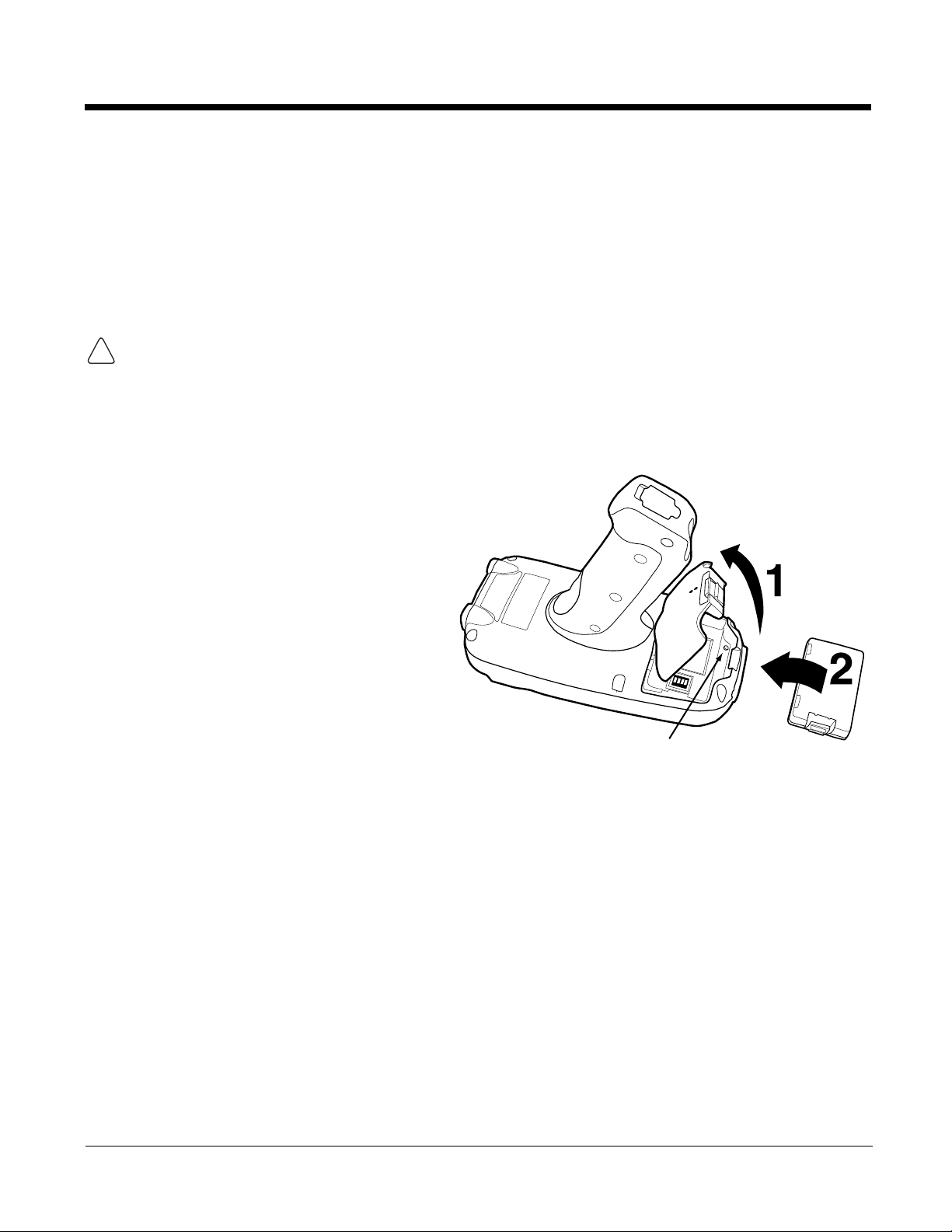
Installing the Main Battery Pack
Press Blue + Backlight keys to put the terminal
in Suspend Mode (see page 3-15) before
installing a new battery.
Mechanical Switch
The battery well area contains a mechanical
switch located under the battery door. When
the battery door is securely fastened, it
presses on the mechanical switch allowing
the terminal to power on and operate
normally.
When the battery door is removed, it no
longer presses on the mechanical switch,
which automatically suspends terminal
operation. The terminal will not resume
normal operations again until the battery
door is re-fastened.
The mechanical switch works as described only when the terminal is running on battery power. If the
terminal is running on AC power (via Dolphin charging peripheral), the mechanical switch will not suspend
the terminal when the battery door is open.
If you open the battery door and remove the battery while the terminal is connected to AC power, the
terminal will continue operating. However, if you remove AC power while the battery door is open and the
battery is removed, the terminal will shut down without suspendin g and you will lose RAM data. To avoid
data loss when removing AC power, always either suspend the terminal or install the battery prior to
removing AC power.
Dolphin® 7850 Mobile Computer
User’s Guide–Preliminary
Rev (d): Preliminary
7/15/2008
3 - 11

Charging Options
When the battery is installed in the terminal, you can insert the terminal into any one of the following
peripherals to charge the main battery pack:
• Dolphin HomeBase Device (see page 9-1)
• Dolphin ChargeBase (see page 11-1)
• One of the charging cables (see page 12-1)
To fully charge the li-ion battery outside the terminal, use one of the following:
• Dolphin QuadCharger Device (see page 10-1)
• Auxiliary Battery Well of the Dolphin HomeBase device
Charge Time
A completely discharged li-ion battery pack requires four(4) hours to charge to full capacity. Subsequent
charge times vary according to the charge level of the battery pack when charging begins.
The li-ion battery packs that ship with Dolphin terminals are co mpletely discharged of power. Theref ore,
charge the main battery pack for a minimum of four(4) hours prior to using the terminal on battery power.
Internal Backup Battery
Located inside the terminal, the backup battery is a 3.6V nickel metal hydride (NiMH) battery.
The internal backup battery prevents the terminal from being reset when you remove the main battery
pack. The backup battery retains RAM data and allows the real-time clock to remain operational for up to
30 minutes. If the terminal is left without the main battery pack for more than 30 minutes, the internal
backup battery discharges and needs to be recharged to function according to specifications.
Note: Even if the internal backup battery fails, data and programs stored in Flash memory are not totally lost, but
the terminal does automatically cold boot when you install a fully charged batt ery pack and you need to reset
the real-time clock.
Charging
The internal backup battery charges off the main battery pack and requires eight(8) hours charge time to
backup RAM data for 30 minutes. You can begin using the Dolphin terminal after charging the main
battery for four(4) hours; however, the internal backup b attery will continue to charge off the main b attery.
To ensure that the internal backup battery functions properly, maintain a consistent power supply for the
first eight(8) hours of terminal operation. This power supply can be external power (using a charging
peripheral) or an installed, charged battery pack or a combination of both.
Guidelines
Follow these guidelines to maximize the life of the terminal’s internal backup battery:
• Keep a charged Li-ion battery pack in the terminal.
• Keep the Dolphin terminal connected to a power source when the terminal is not in use.
Managing Battery Power
Data and files saved on the Dolphin terminal may be stored in RAM memory; therefore, maintain a
continuous power supply to the terminal to help prevent data loss. When you remove a battery pack, insert
another charged battery pack in the Dolphin terminal. If the main battery pack is low, insert the terminal
into a charging peripheral to power the terminal and begin recharging the battery.
Note: If the main battery is low and the terminal is in su spend mode, pressing th e SCAN trigger does not wake the
Dolphin terminal; you must replace the discharged battery with a fully charged battery.
3 - 12 Rev (d): Preliminary
7/15/2008
Dolphin® 7850 Mobile Computer
User’s Guide–Preliminary
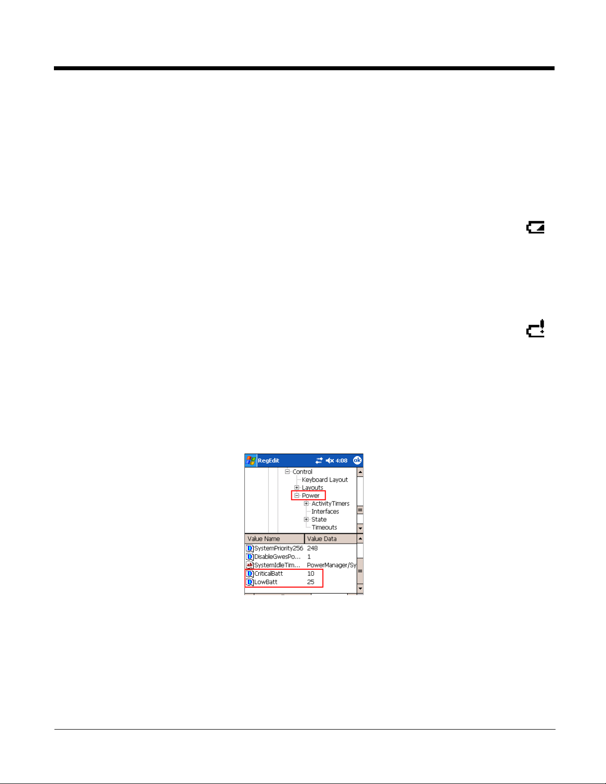
Default Critical and Low Battery Points
Dolphin terminals are programmed to display warnings when the b attery reaches critical and lo w battery
points. The following registry entry sets both warning points:
[HKEY_LOCAL_MACHINE\System\CurrentControlSet\Control\Power]
There are two DWORD values in this registry entry: LowBatt and CriticalBatt. The default values for these
entries are as follows:
“LowBatt”=19 (25%)
This sets the Low Battery point to 25% (19 hex=25 decimal). When the battery hits the
percentage charge specified here, the user is notified by this icon in the Navigation bar .
If the main battery is low and the terminal is in suspend mode, pressing the SCAN or Power
button won’t wake the Dolphin terminal; you must replace the discharged battery with a battery
charged over 25% mark before you can resume terminal operation.
“CriticalBatt”=a (10%)
This sets the Critical Battery point to 10% (a hex= 0 decimal). When the battery hits the
percentage charge specified here, the user is notified by this icon in the Navigation bar .
Note: Warnings do not appear when the terminal is on external power.
Setting Critical and Low Battery Points
Developers can re-reset the default battery points in the RegEdit Power Tool.
1. Tap Start > Power Tools > RegEdit.
2. Drill-down to HKEY_LOCAL_MACHINE > System > CurrentControlSet > Control > Power. The
CriticalBatt and LowBatt values appear in the list.
3. Tap the Value Name to change the Value Data. You can reset the Value Data from 0 (no warning)
to 99 (would warn whenever the charge drops below 99%).
4. Tap OK to save changes.
Note: For more information ab out the RegEdit Power T ool, refer to the Dolphin Power Tools User’s Guide, which is
available for download at www.honeywell.com/aidc.
Dolphin® 7850 Mobile Computer
User’s Guide–Preliminary
Rev (d): Preliminary
7/15/2008
3 - 13
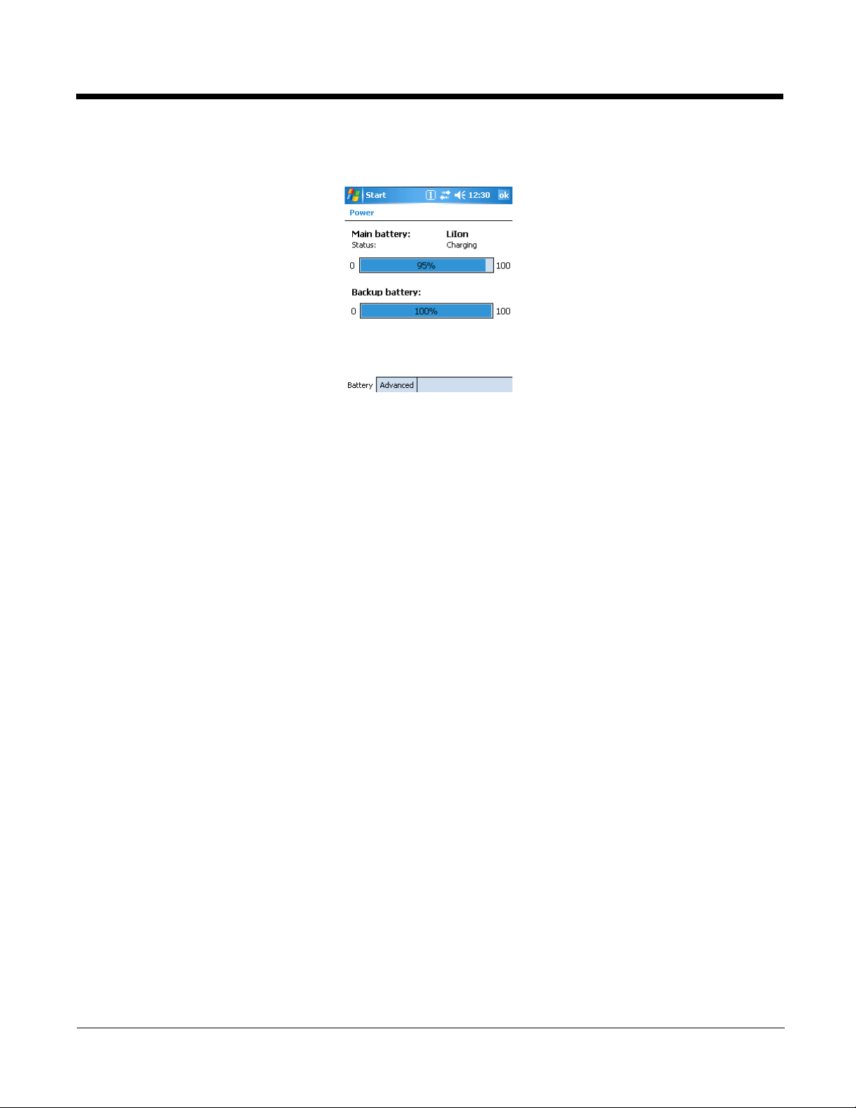
Checking Battery Power
Tap Start > Settings > System tab > Power.
For more information, see Power on page 6-12.
Storage Guidelines
To maintain optimal battery performance, follow these storage guidelines:
• Avoid storing batteries outside the specified range of -4° to 104° F (-20° to 40°C) or in extremely high
humidity.
• For prolonged storage, do not keep batteries stored in a charger tha t is connect ed to a power source.
Guidelines for Battery Pack Use and Disposal
The following are general guidelines for the safe use and disposal of batteries:
• Use only the Li-ion battery packs provided by Honeywell. Use of any b attery not sold/manufactured by
Honeywell may pose a personal hazard to the user.
• Replace defective batteries immediately; using a defective battery could damage the Dolphin terminal.
• Never throw a used battery in the trash. It contains heavy metals and should be recycled a ccording to
local guidelines.
• Don’t use a battery in any other manner outside its intended use in Dolphin terminals and peripherals.
• Don’t short-circuit a battery or throw it into a fire; it can explode and cause severe personal injury.
• Excessive discharge damages a battery. Recharge the battery when your terminal indicates low battery
power.
• If you observe that the battery is physically damaged in some way, please send it to Honeywell or an
authorized Honeywell service center for inspection.
• Although your battery can be recharged many times, it will eventually be depleted. Replace it after the
battery is unable to hold an adequate charge.
• If you are not sure the battery or charger is working properly, please send it to Honeywell or an
authorized Honeywell service center for inspection.
3 - 14 Rev (d): Preliminary
7/15/2008
Dolphin® 7850 Mobile Computer
User’s Guide–Preliminary
 Loading...