

Page 1
7800 SERIES
S7810B Multi-Drop Switch Module
APPLICATION
The Honeywell 7800 SERIES is a microprocessor-based
integrated burner control for automatically fired gas, oil or
combination fuel single-burner applications. The 7800
SERIES is programmed to provide a level of safety, functional
capability and features beyond the capacity of conventional
controls. Functions provided by the 7800 SERIES include
automatic burner sequencing, flame supervision, system
status indication, system or self-diagnostics and
troubleshooting.
The S7810B Multi-Drop Switch Module supports remote
mounting of a Keyboard Display Module, personal computer
communications interface for multi-dropped 7800 SERIES
subnetworks, and remote reset of a 7800 SERIES
Relay Module.
PRODUCT DATA
FEATURES
• Multi-dropped communications bus interface.
• Remote reset.
• Ability to remotely mount a Keyboard Display Module.
Contents
Application ........................................................................ 1
Features ........................................................................... 1
Specifications ................................................................... 2
Ordering Information ......................................................... 2
Installation ........................................................................ 2
Building a Multi-Drop Network .......................................... 3
Operation .......................................................................... 4
65-0228—3
Page 2
7800 SERIES S7810B MULTI-DROP SWITCH MODULE
SPECIFICATIONS
Model: S7810B Multi-Drop Switch Module.
Electrical Ratings:
Voltage and Frequency:
13 Vdc peak full-wave rectified (+20/-15%).
Power Dissipation:
2W maximum.
Terminal Ratings:
Power: 13 Vdc peak full-wave rectified.
Earth ground.
Local ControlBus (1,2,3) and Multi-Drop ControlBus
(6,7,8): 5 Vdc at 1 mA maximum.
Electrical Connector (included): ControlBus: 208727 8-pin
electrical connector.
Environmental Ratings:
Ambient Temperature:
Operating: -40°F to +140°F (-40°C to +60°C).
Storage: -40°F to +150°F (-40°C to 66°C).
Humidity:
85% relative humidity continuous, noncondensing.
Vibration:
0.5G environment.
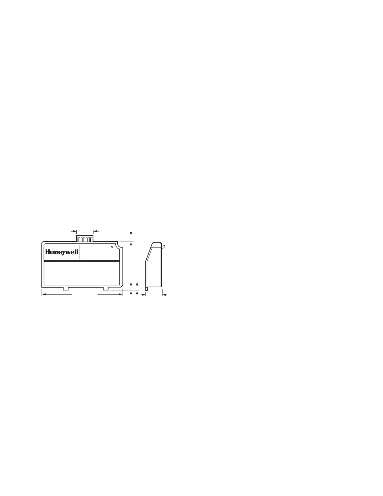
Dimensions: See Fig. 1.
1-1/8 (29)
7/16 (11)
MODE
2-3/4
(69)
5/32
(4)
29/32 (23)
M11349B
BURNER CONTROL
4-27/32 (123)
Fig. 1. Mounting dimensions of S7810B
Multi-Drop Switch Module in in. (mm).
Weight: 4 ounces.
Replacement Part: 208727 eight-pin electrical connector.
INSTALLATION
When Installing this Product...
1. Read these instructions carefully. Failure to follow them
could damage the product or cause a hazardous
condition.
2. Check the ratings given in the instructions and marked
on the product to make sure the product is suitable for
your application.
3. The installer must be a trained, experienced flame
safeguard technician.
4. Disconnect the power supply before beginning
installation to prevent electrical shock and equipment
damage. More than one power supply disconnect can
be required.
5. Wiring must comply with all applicable codes,
ordinances and regulations.
6. After installation is complete, check out product
operation as provided in these instructions.
IMPORTANT:
This equipment can cause interference with radio
communications.
This equipment generates, uses, and can radiate
radio frequency energy, and if not installed and used
in accordance with the Instructions Manual, may
cause interference with radio communication. It has
been tested and found to comply with the limits for a
Class A computing device pursuant to Subpart J of
Part 15 of FCC Rules, which are designed to provide
reasonable protection against such interference
when operated in a commercial environment.
Operation of this equipment in a residential area is
likely to cause interference, in which case, users at
their own expense will be required to take whatever
measures may be required to correct the
interference. Any unauthorized modification of this
equipment may result in the revocation of the
owner’s authority to continue its operation. When
operating the S7810B remotely with a separate
power supply, FCC compliance is not guaranteed
unless an FCC-approved power supply is used.
ORDERING INFORMATION
When purchasing replacement and modernization products from your TRADELINE® wholesaler or distributor, refer to the
TRADELINE® Catalog or price sheets for complete ordering number.
If you have additional questions, need further information, or would like to comment on our products or services, please write or
phone:
1. Your local Honeywell Automation and Control Products Sales Office (check white pages of your phone directory).
2. Honeywell Customer Care
1885 Douglas Drive North
Minneapolis, Minnesota 55422-4386
In Canada—Honeywell Limited/Honeywell Limitée, 35 Dynamic Drive, Scarborough, Ontario M1V 4Z9.
International Sales and Service Offices in all principal cities of the world. Manufacturing in Australia, Canada, Finland, France,
Germany, Japan, Mexico, Netherlands, Spain, Taiwan, United Kingdom, U.S.A.
65-0228—3 2
Page 3

7800 SERIES S7810B MULTI-DROP SWITCH MODULE
Canadian EMI: This digital apparatus does not exceed the
Class A limits for radio noise emission from digital apparatus
set out in the Radio Interference Regulations of the Canadian
Department of Communications.
Le présent appareil numérique n’émet pas de bruits
radioélectriques dépassant les limites applicables aux
appareils numériques de la Classe A prescrites dans le
Règlement sur le brouillage radioeléctrique édicté par le
ministère des Communications du Canada.
Humidity
Install the S7810B where the relative humidity never reaches
the saturation point. The S7810B is designed to operate in a
maximum humidity environment of 85 percent relative humidity
continuous, noncondensing moisture.
Weather
The S7810B is not designed to be weather-tight. When
installed outdoors, protect the S7810B with an approved
weather-tight enclosure.
Vibration
Do not install the S7810B where it could be subjected to
vibration in excess of 0.5G continuous maximum vibration.
Mounting the S7810B Multi-Drop Switch Module.
1. Align the two ears of the Multi-Drop Switch Module with
the two mating slots on the 7800 SERIES Relay Module.
2. Insert the two interlocking ears into the two mating slots
and, with a hinge action, push on the lower corners of
the Multi-Drop Switch Module to secure it to the 7800
SERIES Relay Module.
Wiring (Fig. 2)
1. Refer to Fig. 2 for proper wiring.
2. All wiring must comply with all applicable electrical
codes, ordinances and regulations.
3. Recommended wiring size and type:
a. For ControlBus™ communications, use 22 AWG,
3-wire shielded cable (Belden part number 8723 or
equivalent).
b. For 13 Vdc and remote reset switch operation, use
22 AWG wire insulated for voltages and
temperatures in the application. Suggested wire
types include TW (60°C), THW (75°C) and THHN
(90°C) Terminal identification numbers and letters
shown in Table 1.
Table 1. S7810B and QS7800B Terminal Identification.
S7810B
Signal
Local Bus Data + 1 None
Local Bus Data - 2 None
Common
• Local Bus Common
• +13 Vdc Common
• Remote Reset Common
+13 Vdc 4 None
Remote Reset 5 None
Multi-Drop Bus Common 6 c
Multi-Drop Bus Data + 7 a
Multi-Drop Bus Data - 8 b
4. Wire routing:
a. Do not route the ControlBusª cable in conduit with
line voltage circuits.
b. Do not route the ControlBusª cable close to the
ignition transformers.
c. Route the ControlBusª cable outside of conduit if
properly supported and protected from damage.
d. Route the ControlBusª cable so that all devices are
connected in a daisy chain configuration. See Fig. 3.
5. Maximum wire lengths:
a. RS-485 Communications bus, 4000 feet
(1219 meters).
b. Remote reset switch, 1000 feet (305 meters).
Terminal
3 None
QS7800B
Termin al
BUILDING A MULTI-DROP NETWORK
The subnetwork addressing in the Q7700 Network Interface
Unit (NIU) is not contiguous. It is divided into two blocks,
containing 198 and 24 addresses, respectively. A maximum
multi-drop configuration would include 222 subnetworks
(198 plus 24) on a single Q7700 NIU.
One QS7800B ControlBusª Module card supports up to 31
multi-drop subnetworks without using an RS-485 repeater. If
an RS-485 repeater is used, up to 61 multi-drop subnetworks
can be supported by one QS7800B card. The RS-485 repeater
must be installed between the 30th and 31st subnetworks.
Each subnetwork includes one 7800 SERIES controller with or
without an S7800 Keyboard Display Module and/or an S7830
Expanded Annunciator. An S7810B1007 Multi-Drop Switch
Module is required in each subnetwork. See Fig. 3 for wiring
information.
Subnetworks can be spread evenly (balanced) across the NIU
slots to improve speed of communications.
It is recommended that the multi-drop network be built starting
with slot number 1 of the NIU, subject to the above guidelines.
Record the serial number and physical location of each
S7810B Multi-Drop Switch. This data will be useful when
commissioning the ZM7850 Combustion System Manager
(CSM) software. Refer to CSM manual, form 65-0102, for CSM
commissioning.
3 65-0228—3
Page 4

7800 SERIES S7810B MULTI-DROP SWITCH MODULE
Examples
Network with Maximum of 198 Subnetworks
NIU Slot Numbers 1 2 3 4 5 6 Total
Number of Subnetworks 61 61 61 15 Open Open 198
Subnetworks Balanced 33 33 33 33 33 33 198
The open NIU slots can be used for other QS7800 ControlBus™ Module Cards.
Network with Maximum of 222 Subnetworks
NOTE: For networks that have more than 198 subnetworks,
Number of Subnetworks 61 61 61 15 24 Open 222
Subnetworks Balanced 40 40 40 39 39 24 222
The open NIU slot can be used for other QS7800 ControlBus™ Module Cards.
OPERATION
The S7810B Multi-Drop Switch Module has two
communications ports. One communications port allows
communication on a local bus that contains a burner controller
and a keyboard display module(s) and/or an expanded
annunciator. The other communications port is an addressed
switched port which, when switched on by the QS7800B
the last NIU card slot must have the 199th through
222nd subnetwork attached to it.
NIU Slot Numbers 1 2 3 4 5 6 Total
ControlBusª Module, communicates data from the local bus to
the multi-drop bus. The S7810B also provides a +13 Vdc
output for power to a remote Keyboard Display Module and an
input for a remote reset switch.
A MODE light emitting diode (LED) provides status information
through several blinking patterns. The patterns repeat every
1.6 seconds. See Table 2.
65-0228—3 4
Page 5

7800 SERIES S7810B MULTI-DROP SWITCH MODULE
QS7800B DATA
CONTROLBUS™
A
B
C
5
MODULE
3
1
6
5
7
MOMENTARY
PUSHBUTTON
SWITCH
4
7
5
2
GND
+–
3
INPUT
OUTPUT
3
+–
1
5
1
MULTI-DROP RS-485 COMMUNICATIONS BUS. UP TO 31 S7810B MULTI-DROP SWITCH MODULES (SUBNETWORKS) CAN BE
CONNECTED TO A SINGLE QS7800B CONTROLBUS™ MODULE WITHOUT AN RS-485 REPEATER. UP TO 61 S7810B MULTI-DROP
SWITCH MODULES (SUBNETWORKS) CAN BE CONNECTED TO A SINGLE QS7800B CONTROLBUS™ MODULE WITH AN RS-485
REPEATER. WHEN USING AN RS-485 REPEATER, THE REPEATER MUST BE INSTALLED BETWEEN THE 30TH AND 31ST SUBNETWORKS.
THE SUBNETWORKS MUST BE WIRED IN A DAISY CHAIN CONFIGURATION. RECOMMEND THAT THE QS7800B CONTROLBUS™
2
MODULE BE AT ONE END OF THE DAISY CHAIN.
3
MULTI-DROP COMMUNICTINS BUS TERMINATION RESISTORS:
A. WITHOUT RS-485 REPEATER: MODULES AT THE CLOSEST AND FARTHEST END OF THE DAISY CHAIN REQUIRE TERMINATION
RESISTORS. INSTALL A 120 OHM, 1/4 WATT RESISTOR BETWEEN TERMINALS a AND b OF THE QS7800B CONTROLBUS™ MODULE.
(IF INSTALLED AT ONE END OF DAISY CHAIN), INSTALL A 120 OHM, 1/4 WATT RESISTOR BETWEEN TERMINALS 7 AND 8 OF THE LAST
S7810B MULTI-DROP SWITCH MODULE IN THE DAISY CHAIN.
B. WITH RS-485 REPEATER: WHEN AN RS-485 REPEATER IS USED, TWO DAISY CHAIN CONFIGURATIONS ARE EFFECTIVELY
FORMED. MODULES AT THE CLOSEST AND FARTHEST ENDS OF EACH DAISY CHAIN REQUIRE TERMINATION RESISTORS.
INSTALL A 120 OHM, 1/4 WATT RESISTOR BETWEEN TERMINALS a AND b OF THE QS7800B CONTROLBUS™ MODULE.
(IF INSTALLED AT ONE END OF DAISY CHAIN), INSTALL A 120 OHM, 1/4 WATT RESISTOR BETWEEN INPUT TERMINALS DATA+ AND
DATA- OF THE RS-485 REPEATER. INSTALL A 120 OHM, 1/4 WATT RESISTOR BETWEEN OUTPUT TERMINALS DATA+ AND DATA- OF
THE RS-485 REPEATER. INSTALL A 120 OHM, 1/4 WATT RESISTOR BETWEEN TERMINALS 7 AND 8 OF THE LAST S7810B
MULTI-DROP SWITCH MODULE IN THE SECOND DAISY CHAIN.
LOCAL RS-485 COMMUNICATION BUS. THE DEVICES ON THIS BUS MUST BE WIRED IN A DAISY CHAIN CONFIGURATION. THE
4
ORDER OF INTERCONNECTION IS NOT IMPORTANT. THE MODULES ON THE CLOSEST AND FARTHEST ENDS OF THE DAISY CHAIN
REQUIRE A 120 OHM, 1/4 WATT, TERMINATION RESISTOR BETWEEN TERMINALS 1 AND 2 OR a AND b.
THREE-WIRE SHIELDED CABLE (BELDEN 8723 SHIELDED OR EQUIVALENT) IS RECOMMENDED AND SHOULD BE GROUNDED
5
AS FOLLOWS: IF NO INTERFERENCE IS PRESENT, OR TO REDUCE CAPACITIVE INTERFERENCE, THE SHIELD SHOULD BE
GROUNDED AT ONE END. WHEN GROUNDING ONLY ONE END OF THE SHIELD, THE SHIELD END CLOSEST TO THE S7810B
MULTI-DROP SWITCH MODULE SHOULD BE ATTACHED TO EARTH GROUND. TO REDUCE INDUCTIVE INTERFERENCE (RF
INTERFERENCE), THE SHIELD SHOULD BE GROUNDED AT BOTH ENDS.
REFER TO QS7800B DATA CONTROLBUS™ MODULE INSTRUCTIONS, FORM 65-0227, FOR INSTALLATION INSTRUCTIONS.
6
THE MULTI-DROP BUS COMMON, S7810B TERMINAL 6, AND THE LOCAL BUS COMMON, S7810B TERMINAL 3, MUST NOT BE
7
ELECTRICALLY CONNECTED TOGETHER.
TERMINAL NUMBERS ARE ON 203541 5-WIRE CONNECTOR (SUPPLIED WITH REMOTE MOUNTING BRACKET).
8
GND
RS-485
REPEATER
3
5
2
8 7 6 5 4 3 2 1
S7810B MULTI-DROP
SWITCH MODULE
7800 SERIES
RELAY MODULE
8 7 6 5 4 3 2 1
S7810B MULTI-DROP
SWITCH MODULE
7800 SERIES
RELAY MODULE
5
2
S7800 REMOTE
KEYBOARD DISPLAY
MODULE
8 7 6 5 4 3 2 1
S7810B MULTI-DROP
SWITCH MODULE
7800 SERIES
RELAY MODULE
1 2 3 4 5 A B C
8
4
M11348C
S7830 EXPANDED
ANNUNCIATOR
Fig. 2. Wiring S7810B Multi-Drop Switch Module.
5 65-0228—3
Page 6

7800 SERIES S7810B MULTI-DROP SWITCH MODULE
Fig. 3. Explanation of MODE LED light patterns.
Pattern in Seconds Description
OFF LINE: The S7810B is not receiving any messages from the QS7800B
ControlBus™ Module.
LED is off for 1.5 seconds and on for 0.1 second.
0.1
Check for:
• Wiring problems on multi-drop bus (loose connections, broken wires, or
1.5
M13028
• QS7800B ControlBus™ Module or S7810B Multi-drop Switch Module
• QS7800B ControlBus™ Module not properly seated in Q7700 Network
• No power to Q7700 Network Interface Unit.
SENSING: The S7810B is receiving messages from the QS7800B
ControlBus™ Module.
0.8
0.8
LED is off for 0.8 second and then on for 0.8 second.
The SENSING pattern reverts to the OFF LINE pattern when it has not
M13029
received a message from the QS7800B ControlBus™ Module for more
than four seconds.
ALARM LISTEN: The S7810B monitors devices on the local bus and
1.6
(RETURNING TO
EITHER SENSING
OR SWITCH
CLOSED PATTERN)
M13030A
notes any alarm condition.
LED is on for 1.6 seconds then reverts to the SENSING or switch closed
pattern.
miswired connections.
not connected to multi-drop bus.
Interface Unit slot.
ON
OFF
1.3
OR
0.1
0.8
0.1
M13031
M13032
M13033
SWITCH CLOSED: The S7810B multi-drop bus port switch has been
switched on by the QS7800B ControlBus™ Module and data from the
local bus is being sent to the multi-drop bus.
LED is off for 0.1 second and on for 0.1 second, repeating for the 1.6
seconds duration.
FAULT: The S7810B has an internal fault.
LED is off for 1.3 seconds, on for 0.1 second, off for 0.1 second, on for 0.1
second. (Pattern is mainly off with two short blinks.)
STEADY STATE CONDITIONS:
LED is always OFF. S7810B is either defective or no power has been
applied to it.
LED is always ON. S7810B is defective.
65-0228—3 6
Page 7

7 65-0228—3
Page 8

Automation and Control Solutions
Honeywell International Inc. Honeywell Limited-Honeywell Limitée
1985 Douglas Drive North 35 Dynamic Drive
Golden Valley, MN 55422 Scarborough, Ontario M1V 4Z9
customer.honeywell.com
® U.S. Registered Trademark
© 2005 Honeywell International Inc.
65-0228—3 G.R. Rev.06-05
 Loading...